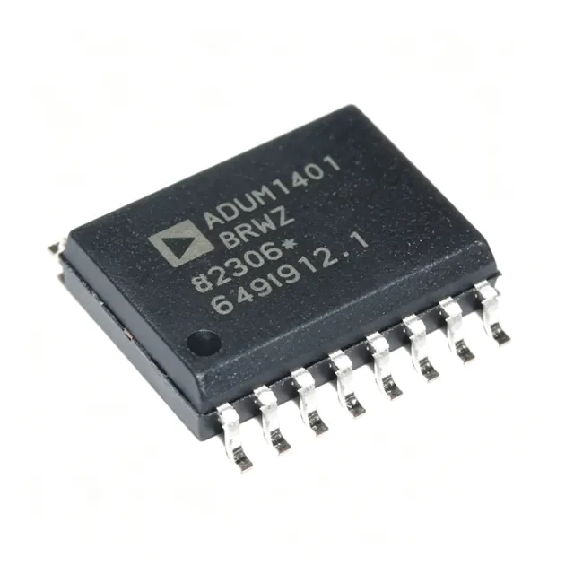
What Is the ADUM4221BRWZ and Why Does It Matter for Your Design?
The ADUM4221BRWZ is an isolated half-bridge gate driver from Analog Devices that delivers 4 A peak output current, 5 kVrms isolation (rated for 1 minute), and 100 kV/us common-mode transient immunity in a 16-lead wide-body SOIC package. It drives high-side and low-side N-channel MOSFETs or IGBTs in power conversion applications such as industrial motor drives, solar inverters, isolated DC-DC converters, and EV chargers. The part uses Analog Devices' iCoupler magnetic coupling technology, offers adjustable dead time via an external resistor on the DT pin, and operates across an input supply range of 2.5 V to 6.5 V with output supplies (VDDA/VDDB) from 4.5 V to 18 V. As of 2026-09-02, the ADUM4221BRWZ is active in lifecycle status, stocked at 99,999 units on XAIPART with MOQ 1, priced from $4.85 (qty 1) down to $3.10 (qty 1000). The device is certified to UL 1577 and VDE 0884-10 (IEC 60747-5-5), with a working voltage of 560 Vrms, and it carries RoHS compliance and MSL 3 (168 hours) ratings.
In the power-management signal chain, an isolated gate driver sits between the low-voltage controller (MCU or DSP) and the power switches. It transfers PWM signals across the galvanic isolation barrier while supplying the current needed to charge and discharge gate capacitance, protecting low-voltage logic from high-voltage transients. The ADUM4221BRWZ fills that role with a 60 ns typical propagation delay, dual non-inverting inputs (VIA and VIB) for independent channel control, and an active-high DISABLE pin for output shutdown. If you need current stock, pricing tiers, or the full datasheet, see the ADUM4221BRWZ product page.
How Do You Select and Design In the ADUM4221BRWZ?
Selection starts with matching the driver's electrical envelope to your power stage. Verify these boundaries against the verified specifications:
| Parameter | ADUM4221BRWZ (verified) |
|---|---|
| Technology | Magnetic Coupling (iCoupler) |
| Number of Channels | 2 |
| Peak Output Current | 4 A |
| Isolation Voltage | 5000 Vrms |
| Input Supply (VDD1) | 2.5 V to 6.5 V |
| Output Supply (VDDA/VDDB) | 4.5 V to 18 V |
| UVLO Threshold | 7.5 V (typical) |
| Propagation Delay | 60 ns (typical) |
| CMTI | 100 kV/us |
| Adjustable Dead Time | Yes (external resistor) |
| Package | 16-SOIC (wide body) |
| Operating Temperature | -40°C to +125°C |
| Isolation Standards | UL 1577; VDE 0884-10 (IEC 60747-5-5) |
Design-in steps based on the verified data:
1. Match the input interface. The CMOS input interface accepts 2.5 V to 6.5 V logic, so it connects directly to 3.3 V or 5 V microcontrollers without level shifting. Use VIA and VIB for independent high-side/low-side control, and pull DISABLE high to shut down both outputs.
2. Set the dead time. Adjust dead time through an external resistor on the DT pin. Place this resistor close to the DT pin to minimize noise pickup. Proper dead-time setting prevents shoot-through in half-bridge topologies, improving both efficiency and reliability.
3. Plan the output supplies. Each output channel has its own supply pins: VDDA (pin 9) and VDDB (pin 14) accept 4.5 V to 18 V, accommodating gate drive voltages for both MOSFETs and IGBTs. Both channels share a typical UVLO threshold of 7.5 V, so ensure your supply rails exceed this before releasing the driver into operation. Provide adequate decoupling on the output supplies to handle the 4 A peak gate currents.
4. Respect the isolation ratings. The barrier is rated 5 kVrms for 1 minute with a 560 Vrms working voltage. Confirm your system's working voltage requirement fits within 560 Vrms, or apply the appropriate derating for your safety standard [VERIFY_NEEDED: system-level creepage/clearance derating requirements for specific end applications].
5. Manage PCB layout. Minimize parasitic inductance in the gate drive loop by keeping the driver close to the power switches. The 100 kV/us CMTI rating ensures stable operation under the fast dv/dt transients typical of hard-switched bridges, but short, tight gate loops preserve that margin. Decouple GND1 (pins 2, 7, 16), GNDA (pin 11), and GNDB (pin 12) appropriately for their respective domains.
6. Handle assembly correctly. The part is MSL 3 (168 hours floor life) and surface-mount, so bake or control floor time per your reflow process [DATA_NEEDED: MSL reflow classification reference]. It operates from -40°C to +125°C, covering industrial and automotive-adjacent ambient requirements.
What Are the Drop-In Alternatives and How Do They Compare?
All alternatives below come from the verified XAIPART database. Within Analog Devices, packaging and logic variants exist; cross-brand options require pinout verification before substitution.
| Alternative | Relationship to ADUM4221BRWZ | Key Difference |
|---|---|---|
| ADUM4221BRIZ | Same die, drop-in replacement | Tube packaging instead of tape and reel; identical electrical specifications; same 16-SOIC pinout |
| ADUM4221BRIZ-RL | Same die, tape and reel packaging | Packaging variant for automated assembly |
| ADUM4223BRWZ | Pin-compatible, 16-SOIC | Single input with enable instead of dual inputs; no adjustable dead time; same 4 A output and 5 kVrms isolation |
| ADUM4221-1BRIZ | Single-input version | No adjustable dead time |
| ISO7721 (TI) | Cross-brand dual-channel isolator | Different output drive configuration; pinout may differ — verify before substitution |
| Si8233 (Silicon Labs) | Cross-brand isolated half-bridge driver | 4 A output; pinout may differ — verify before substitution |
Choose the ADUM4221BRWZ when your control scheme needs dual independent inputs and adjustable dead time. If a simpler single-input interface with enable suffices and you can tolerate fixed (non-adjustable) dead time, the ADUM4223BRWZ is pin-compatible but not a direct functional replacement. For procurement flexibility, the ADUM4221BRIZ is the safest like-for-like swap — the 'Z' suffix indicates lead-free finish and 'RI' indicates tube packaging, with identical electrical specifications.
What Is the Market Position, Lifecycle Status, and Supply Situation for the ADUM4221BRWZ?
The ADUM4221BRWZ is an active lifecycle part per the verified XAIPART database, meaning Analog Devices continues to manufacture it and it is not recommended for new designs to avoid [DATA_NEEDED: NRND status or discontinuation notice, if any]. Supply is healthy: XAIPART lists 99,999 units in stock with a minimum order quantity of 1 as of 2026-09-02, and distributor data indicates typical lead times of 1 to 4 weeks depending on quantity, with 'ships today' availability for in-stock items at major distributors as of 2026-08-22. Pricing tiers as of 2026-09-02 run $4.85 (qty 1), $4.36 (qty 10), $3.88 (qty 100), $3.49 (qty 500), and $3.10 (qty 1000) — a 36% unit-price reduction from single-unit to thousand-piece volume. For engineers planning long production runs, active status plus deep distributor stock reduces obsolescence risk in the near term; confirm long-term commitment directly with Analog Devices [VERIFY_NEEDED: manufacturer long-term supply commitment statement].
What Trends Should Buyers and Designers Watch Around Isolated Gate Drivers?
Three trends anchored to the ADUM4221BRWZ's verified specifications deserve attention:
Higher CMTI demands. As wide-bandgap power stages switch faster, gate drivers face steeper common-mode transients. The ADUM4221BRWZ's 100 kV/us CMTI already addresses fast dv/dt environments in solar inverters and motor drives; when evaluating future drivers, treat CMTI as a primary selection criterion alongside peak current.
Configurability over fixed function. The adjustable dead time (external DT resistor) and dual-input architecture of the ADUM4221BRWZ reflect demand for tunable switching behavior. Compare against the ADUM4223BRWZ's fixed-dead-time, single-input approach: designs prioritizing efficiency optimization and EMI reduction favor adjustability, while simplified control schemes favor the single-input variant.
Wide supply compatibility. The 2.5 V to 6.5 V input range and 4.5 V to 18 V output range let one driver serve multiple logic families and gate voltage targets, reducing qualification burden across product variants. Combined with the -40°C to +125°C operating range and 5 kVrms isolation certified to UL 1577 and VDE 0884-10, the part covers the breadth of industrial, renewable energy, and EV charging applications without redesign.
Buyers should also watch packaging economics: the availability of BRIZ (tube) and BRIZ-RL (tape and reel) variants of the same die means you can align packaging with your assembly volume and negotiate pricing across variants. Monitor the XAIPART stock page for real-time inventory, and consult the XAIPART technical guides for adjacent power-design topics.
Comments
Be the first to comment.
🔐 Please sign in to post a comment.
Don't have an account? Sign up