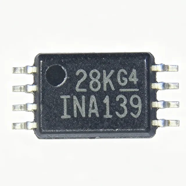
What Is the INA240A1QPWRQ1 and Why Do Automotive Designers Choose It?
The Texas Instruments INA240A1QPWRQ1 is an AEC-Q100 qualified, voltage-output current sense amplifier with a fixed gain of 20 V/V, an exceptionally wide common-mode voltage range of -4 V to 80 V independent of its 2.7 V to 5.5 V supply, and enhanced PWM rejection for in-line motor phase current sensing. It comes in an 8-pin TSSOP (PW) package, operates from -40°C to +125°C, and is currently active and in stock at XAIPART with 99999 units available, priced from $2.75 at qty 1 down to $1.35 at qty 1000 as of 2026-09-04.
A current sense amplifier measures the small voltage drop across a shunt resistor that rides on a high common-mode potential, converting it into a ground-referenced analog voltage for an ADC or controller. The INA240A1QPWRQ1 stands out because its enhanced PWM rejection suppresses the large common-mode transients generated at every switching edge of PWM-driven inverter stages — transients that saturate conventional current sense amplifiers and corrupt the measurement for microseconds. Its zero-drift architecture delivers very low offset and drift for precision DC accuracy without periodic calibration, and its -4 V negative common-mode capability accommodates the flyback period of solenoid and motor drive applications.
What Are the Verified Key Specifications of the INA240A1QPWRQ1?
The following specifications come directly from the XAIPART verified product database and the TI INA240-Q1 datasheet:
| Parameter | Value |
|---|---|
| Gain (A1 version) | 20 V/V |
| Common-mode voltage range | -4 V to 80 V |
| Supply voltage range | 2.7 V to 5.5 V |
| Configuration | High-side / low-side, bidirectional |
| Architecture | Zero-drift, enhanced PWM rejection |
| Qualification | AEC-Q100 Automotive |
| Operating temperature | -40°C to +125°C |
| Output type | Voltage output, analog |
| Reference pins | REF1 and REF2 (uni/bidirectional) |
| Package | 8-TSSOP (PW), surface mount |
| Channels | 1 |
For bandwidth, input offset voltage, quiescent current, and RoHS status, consult the official TI INA240-Q1 datasheet linked in the citations below.
How Do You Design In the INA240A1QPWRQ1? A Practical Technical Guide
Pinout and connections. The 8-TSSOP pinout assigns Pin 1 (INP) and Pin 2 (INN) to the shunt resistor's positive and negative Kelvin terminals, Pins 3 and 4 (REF1, REF2) set the bidirectional output bias, Pin 5 (OUT) delivers the ground-referenced analog output, Pin 6 (VS) takes the 2.7 V to 5.5 V supply, Pin 7 is GND, and Pin 8 is NC.
Unidirectional vs. bidirectional configuration. Use the REF1 and REF2 pins to configure the output for unidirectional or bidirectional operation. For battery current monitoring or in-line motor phase sensing where current flows both ways, bias the output at mid-scale by driving REF1/REF2 appropriately so charge and discharge currents both map into the ADC range. For one-directional overcurrent protection, ground-referencing the reference pins maximizes output swing per amp.
Gain and shunt selection. The A1 version's 20 V/V is the lowest gain in the INA240-Q1 family (A2 = 50 V/V, A3 = 100 V/V, A4 = 200 V/V per the TI datasheet). The design tip from the verified data: choose the lowest gain version that meets your ADC input range to keep shunt resistor power dissipation in check — a lower gain permits a smaller shunt value for the same full-scale output, reducing heat at high load currents.
Layout for PWM rejection. Place the INA240 close to the shunt and use tight, symmetric Kelvin routing to INP and INN to preserve the enhanced PWM rejection performance. Asymmetric trace resistance or inductance in the input path degrades the device's ability to reject the tens-of-volts common-mode steps created by inverter switching edges.
Supply and interface. The 2.7 V to 5.5 V supply range connects directly to typical 3.3 V or 5 V automotive ADC rails, and the ground-referenced analog output interfaces to standard microcontroller ADC inputs without level shifting for non-isolated sensing topologies.
What Are the Main Applications and Usage Scenarios?
In-line motor phase current sensing (HEV/EV traction inverters, servo drives). Placed in series with each motor phase, the 20 V/V gain converts the shunt drop to a ground-referenced output while enhanced PWM rejection keeps the measurement valid at every switching edge, and the -4 V common-mode range accommodates phase voltages below ground during flyback.
Automotive battery current monitoring (12 V and 48 V systems). The 80 V common-mode ceiling supports 48 V systems with headroom, AEC-Q100 qualification satisfies OEM requirements, and zero-drift DC accuracy supports coulomb counting and state-of-charge estimation without periodic field calibration.
Solenoid current monitoring. The -4 V common-mode range handles flyback excursions while PWM rejection enables closed-loop current control for precise actuator positioning at low setpoints.
DC bus current sensing in industrial drives and solar inverters. The 80 V ceiling covers 48 V buses with margin; a small RC filter on the output helps reject residual switching noise.
Overcurrent protection and eFuse feedback. Fast response to common-mode transients reports genuine overcurrent events without blanking artifacts, and the bidirectional reference configuration allows a programmable trip threshold.
48 V mild-hybrid systems. The 80 V rating provides headroom above the 48 V rail including load-dump and transient conditions from belt-starter-generator and DC-DC converter stages.
Which Alternatives and Drop-In Replacements Exist for the INA240A1QPWRQ1?
All verified alternatives come from the same INA240 family and share the identical 8-TSSOP (PW) pinout, making them pin-to-pin compatible:
| Part Number | Gain | Qualification | Pinout | Key Difference |
|---|---|---|---|---|
| INA240A1QPWRQ1 | 20 V/V | AEC-Q100 | 8-TSSOP (PW) | Reference device |
| INA240A1PW | 20 V/V | Industrial (not Q1) | 8-TSSOP (PW) | Industrial grade, same gain |
| INA240A2QPWRQ1 | 50 V/V | AEC-Q100 | 8-TSSOP (PW) | Higher gain for small shunts |
| INA240A3QPWRQ1 | 100 V/V | AEC-Q100 | 8-TSSOP (PW) | Higher gain option |
| INA240A4QPWRQ1 | 200 V/V | AEC-Q100 | 8-TSSOP (PW) | Highest gain option |
| INA240A2PW | 50 V/V | Industrial (not Q1) | 8-TSSOP (PW) | Industrial, 50 V/V |
Selection is purely a gain-vs-shunt-power trade-off: choose 20 V/V when your shunt voltage is large or your ADC range is wide; choose 50 V/V (A2) or higher when sensing very small shunt drops. For non-automotive builds, the industrial INA240A1PW is pin-compatible and cost-effective. There is no guaranteed pin-compatible cross-brand drop-in; Analog Devices' AD8418 is functionally similar (20 V/V, PWM-rejection-oriented, automotive) but not pin-identical, so it requires PCB layout review rather than a true drop-in swap.
What Is the Market Position, Lifecycle, and Supply Situation?
The INA240A1QPWRQ1 carries an active lifecycle status in the XAIPART database, meaning Texas Instruments continues to produce it and no discontinuation notice applies. XAIPART currently stocks 99999 units with an MOQ of 1, and tier pricing runs $2.75 (qty 1), $2.45 (qty 10), $1.95 (qty 100), $1.65 (qty 500), and $1.35 (qty 1000) as of 2026-09-04. As of 2026-08-28, DigiKey lists it with same-day shipping and Mouser lists inventory and pricing. Standard factory lead time for TI current sense amplifiers generally ranges from several weeks to a few months during allocation, so confirm current lead times before committing production schedules.
What Should Buyers Watch Going Forward?
Anchor your BOM decisions to the verified specs: the 80 V common-mode ceiling already covers 48 V mild-hybrid architectures with transient headroom, making this part well-positioned as 48 V adoption grows in automotive platforms. Because all INA240-Q1 gain variants share the same 8-TSSOP pinout, you can dual-source gains (20 V/V and 50 V/V) on one PCB footprint and adjust gain per application later — a valuable hedge for platform designs. Watch inventory position at multiple distributors since availability fluctuates; for production quantities, verify current stock and RFQ options on the INA240A1QPWRQ1 product page on XAIPART. Also monitor the non-Q1 INA240A1PW for cost-optimized industrial builds where AEC-Q100 documentation is not formally required. For full electrical characteristics, always download the current datasheet from TI's official INA240-Q1 datasheet. Browse the broader Amplifier ICs catalog on XAIPART for related sensing devices.
Comments
Be the first to comment.
🔐 Please sign in to post a comment.
Don't have an account? Sign up