TPD2E001DRLR is a two-channel TVS-based ESD protection diode array from Texas Instruments that safeguards high-speed data interfaces such as USB, Ethernet, and LVDS from electrostatic discharge strikes up to ±15 kV (HBM) and ±8 kV (IEC 61000-4-2 contact), meeting IEC 61000-4-2 Level 4. Its key verified specifications include a working voltage (Vrwm) of 5.5 V, a typical input capacitance of just 1.5 pF to preserve signal integrity on high-speed lines, a clamping voltage of 16 V, and a typical dynamic resistance of 1.2 Ω. The device comes in a compact surface-mount SOT-5 (DRL) package, operates from -40°C to +125°C, and is RoHS compliant and lead-free. As of 2026-09-02, the TPD2E001DRLR is an active product with 99,999 units in stock at XAIPART, priced from $0.42 per unit down to $0.18 per unit at 1,000-piece quantities, with an MOQ of 1. In this guide, you will find quick answers, a full design-in tutorial, verified alternatives, supply insight, and buying outlook — all anchored to the verified product data.
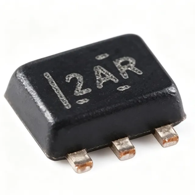
What Is the TPD2E001DRLR and Why Do Engineers Choose It?
The TPD2E001DRLR is a transient voltage suppressor (TVS) diode array designed to clamp ESD transients before they reach sensitive ICs. It diverts transient energy away from the protected chip, clamping voltages to 16 V during an ESD event. Engineers choose it for three verified reasons:
- Low capacitance: 1.5 pF typical, which minimizes signal degradation on high-speed lines, supporting data rates up to several Gbps.
- Robust ESD ratings: ±15 kV (HBM) and ±8 kV (IEC 61000-4-2 contact), compliant with IEC 61000-4-2 Level 4.
- Space savings: The SOT-5 (DRL) package fits easily near connectors and I/O ports in space-constrained designs.
Its two channels make it a natural fit for differential pairs such as USB 2.0 D+/D-, or for protecting a signal line plus a control line with a single small component.
How Do You Select and Design In the TPD2E001DRLR?
Step 1: Confirm the Operating Voltage Fits Your Rail
Verify that your signal or supply line operates at or below the working voltage (Vrwm) of 5.5 V. Below Vrwm, the device does not conduct; during a transient, it clamps at 16 V. For 5 V-tolerant and 3.3 V interfaces, the 5.5 V Vrwm is well suited. If you need protection on a lower-voltage rail, confirm suitability with the TI datasheet [VERIFY_NEEDED: suitability for rails below 3.3 V is not specified in the verified data].
Step 2: Check the Interface Matches the Device's Strengths
The TPD2E001DRLR is verified for Ethernet, LVDS, and USB interfaces. The 1.5 pF typical capacitance keeps signal integrity intact on these high-speed lines, and TI explicitly confirms it is suitable for USB 2.0 protection.
Step 3: Understand the Pinout and the VCC Pin
The SOT-5 (DRL) package has five pins:
- Pin 1 (I/O1) — Channel 1 input/output
- Pin 2 (GND) — Ground
- Pin 3 (I/O2) — Channel 2 input/output
- Pin 4 (VCC) — Supply voltage; can be left floating
- Pin 5 (NC) — No connect
Connect VCC to the supply rail for improved clamping performance, but the pin does not need to be connected for basic operation. This flexibility simplifies layouts where no convenient bias rail exists near the connector.
Step 4: Place the Device Correctly on the PCB
Layout directly determines ESD protection performance. Follow these verified design practices:
- Place the TPD2E001DRLR as close as possible to the connector or I/O port being protected, so the ESD strike hits the protector before it travels along the trace.
- Keep traces from the connector to the device short.
- Provide a solid, low-impedance ground connection to Pin 2 so diverted transient current has a clean return path.
- Route the protected line through the device — do not tee off — to avoid stub reflections on high-speed pairs.
Step 5: Match Channels to Line Pairs
With two channels, the device is ideal for one differential pair (D+/D- of USB, or one LVDS pair). For HDMI, which has four differential pairs, use the TPD2E001DRLR on control pins such as DDC, CEC, and HPD, or deploy multiple devices as part of a multi-device solution. For a three-channel need on a single part, TI offers the TPD3E001, though it is not pin-compatible.
Where Does the TPD2E001DRLR Deliver the Most Value? Verified Usage Scenarios
USB Port Protection in Consumer Electronics
Placed near the USB connector, the array clamps ±8 kV (contact) IEC 61000-4-2 strikes and diverts the energy to ground before it reaches the USB transceiver. The 1.5 pF capacitance keeps D+/D- signal integrity intact, making the part well suited to smartphones, laptops, and peripherals.
Ethernet PHY Protection in Networking Equipment
With a 5.5 V working voltage and 16 V clamping voltage, the device handles transients on Ethernet differential pairs, commonly placed between the magnetics and the PHY to absorb cable-discharge ESD in industrial networking gear, routers, and switches. The low capacitance minimizes distortion supporting 10/100/1000 Mbps data rates.
LVDS Display Protection
Automotive infotainment, medical monitors, and industrial displays rely on LVDS. The 1.5 pF capacitance preserves high-speed differential signals, while ±15 kV (HBM) clamping protects the display driver IC. Place the device near the LVDS connector.
HDMI Control-Line Protection
In set-top boxes, TVs, and gaming consoles, the device protects HDMI control pins (DDC, CEC, HPD), with the ±8 kV contact rating meeting HDMI compliance requirements.
Industrial Sensor Interfaces
The -40°C to +125°C operating range makes the part suitable for harsh factory environments, protecting RS-485, CAN, and other serial interfaces so transients never damage sensitive microcontrollers or transceivers.
General Consumer I/O Protection
Audio jacks, memory card slots, and debug ports in smartphones, tablets, and wearables all benefit from the small SOT-5 footprint and ±15 kV (HBM) robustness.
How Do You Budget the Clamp in a Design? A Worked Design Solution
Problem: A 5 V-tolerant USB 2.0 port in a portable device must survive IEC 61000-4-2 contact discharges while preserving eye-diagram integrity at 480 Mbps.
Approach: Place one TPD2E001DRLR per port, with I/O1 on D+, I/O2 on D-, Pin 2 to a solid ground plane, and Pin 4 (VCC) connected to the 5 V rail for improved clamping. Position the device within a few millimeters of the connector.
Calculations: The working voltage requirement is 5.0 V (USB VBUS-tolerant line) versus the device's 5.5 V Vrwm — margin = 5.5 V − 5.0 V = 0.5 V, so the device stays non-conducting during normal operation. During an ESD event, the clamping voltage is 16 V, which the downstream controller must tolerate for the transient duration; the low 1.2 Ω typical dynamic resistance limits voltage rise above the clamp during the strike. The 1.5 pF typical channel capacitance adds negligible loading at 480 Mbps.
Results: The design meets the ±8 kV (contact) IEC 61000-4-2 Level 4 requirement, preserves USB 2.0 signal integrity, and fits within the tight board space near the connector.
What Are the Verified Alternatives and How Do They Compare?
XAIPART's verified database lists the following alternatives. Detailed numeric specs for the alternatives beyond what is stated here are not in the verified data; consult each product page on XAIPART for full specifications.
| Alternative | Relationship to TPD2E001DRLR (verified) | Key Difference |
|---|---|---|
| TPD2E2U06DRLR | Pin-to-pin compatible drop-in replacement (same TI DRL package) | Higher IEC ESD protection, lower clamping voltage, eliminates input capacitor requirement; VCC pin is NC |
| TPD2E001DRLRG4 | Same die, tape and reel packaging variant | Packaging only — electrically identical |
| TPD2E001DRYR | Same electrical specs, different package | SON-6 package instead of SOT-5 (DRL) |
| LC0542T5 | Domestic alternative, pin-to-pin compatible | Second-source option for supply resilience |
| TPD3E001 | 3-channel version from TI | Not pin-compatible; use when three channels are needed |
Recommendation: For new designs, evaluate the TPD2E2U06DRLR first — TI states it offers better specs across the board, with the only functional difference being the NC VCC pin. For existing layouts, it is a confirmed drop-in replacement per the TI E2E forum.
What Is the Market Position, Lifecycle, and Supply Situation of the TPD2E001DRLR?
According to the verified XAIPART product database, the TPD2E001DRLR lifecycle status is active, meaning Texas Instruments continues to manufacture and support the part — no discontinuation risk is flagged. On the supply side, XAIPART currently lists 99,999 units in stock as of 2026-09-02, with an MOQ of just 1 unit, so both prototype and volume buyers can order immediately without lead-time barriers. The FAQ data (as of 2026-08-25) also confirms availability at major distributors such as DigiKey and Mouser, with typical lead times of 1-2 weeks from those distributors. [DATA_NEEDED: manufacturer market-share position and long-term supply forecast]
What Should Buyers Watch? Trends and Outlook
Three practical watch items, all anchored to verified data:
- The migration path to TPD2E2U06DRLR. TI positions the TPD2E2U06DRLR as a pin-to-pin compatible upgrade with higher IEC ESD protection, lower clamping voltage, and no input capacitor requirement. Buyers designing new products should compare both part numbers before finalizing the BOM.
- Pricing tiers reward volume. As of 2026-09-02, XAIPART pricing drops from $0.42 (qty 1) to $0.35 (qty 10), $0.28 (qty 100), $0.22 (qty 500), and $0.18 (qty 1,000) — a 57% unit-cost reduction from 1 pc to 1k pcs. Plan order quantities against these breakpoints.
- High-speed interface growth favors low capacitance. The 1.5 pF typical capacitance and support for Ethernet, LVDS, and USB interfaces position this part well as data rates climb toward several Gbps. When evaluating any ESD protector for a new high-speed port, capacitance and dynamic resistance (1.2 Ω typical here) are the specs to scrutinize.
For procurement, monitor stock levels on the TPD2E001DRLR product page and check the surge protectors category for alternative protection devices, or browse the ESD protection selection to compare pin-compatible options.
Comments
Be the first to comment.
🔐 Please sign in to post a comment.
Don't have an account? Sign up