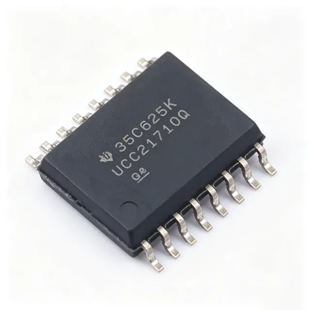
UCC21710-Q1: What Is It and Why Do Engineers Choose It?
The Texas Instruments UCC21710-Q1 is a galvanically isolated single-channel gate driver that delivers up to ±10 A peak source and sink current for SiC MOSFETs and IGBTs switching up to 1700 V. It provides 5700 Vrms reinforced isolation in a 16-SOIC (D) surface-mount package, uses capacitive coupling for high common-mode transient immunity, and is AEC-Q100 qualified for automotive use. Protection features include overcurrent and short-circuit detection via shunt sensing, an active Miller clamp, fault reporting, UVLO on both input and output sides, and isolated analog-to-PWM sensing for temperature or voltage monitoring. As of 2026-08-30, the part is active in lifecycle status and XAIPART lists 99999 units in stock with an MOQ of 1 and a base price of $0 as of 2026-08-30 [VERIFY_NEEDED: distributor pricing confirmation]. This guide explains how to select, design in, and source the UCC21710-Q1, compares its drop-in alternatives, and outlines what buyers should watch in 2025–2026.
What Are the Key Specifications of the UCC21710-Q1?
| Parameter | UCC21710-Q1 (Verified) |
|---|---|
| Output current | ±10 A peak source/sink |
| Isolation voltage | 5700 Vrms (reinforced) |
| Number of channels | 1 |
| Package | 16-SOIC (D), surface mount |
| Switching voltage | Up to 1700 V (SiC MOSFET/IGBT) |
| Isolation technology | Capacitive coupling |
| Automotive qualification | AEC-Q100 (Q1 suffix) |
| Input type | Digital |
| Protection | OC/short-circuit via shunt sensing, active Miller clamp, fault reporting, UVLO both sides |
| Sensing | Isolated analog-to-PWM (temperature/voltage monitoring) |
| Propagation delay | [DATA_NEEDED: propagation delay] |
| CMTI | [DATA_NEEDED: common-mode transient immunity] |
| VDD supply range | [DATA_NEEDED: input supply voltage range] |
| Operating temperature | [DATA_NEEDED: operating temperature range] |
| Fault response time | [DATA_NEEDED: overcurrent/short circuit detection time] |
The datasheet is available from TI at the link cited below. The 54-page document details protection behavior, analog sensing, and application circuits.
How Do You Design In the UCC21710-Q1?
Designing with the UCC21710-Q1 follows a repeatable process for high-power SiC and IGBT half-bridges.
Step 1 — Bias supplies. Provide proper bias supplies on both sides of the isolation barrier. TI recommends the UCC14240-Q1 isolated power supply for the output side. Output-side supply range is [DATA_NEEDED: output supply voltage range], so verify the VDD–VEE window against your target transistor's gate rating before finalizing the rail.
Step 2 — Gate loop layout. Minimize gate loop inductance. The ±10 A peak drive current means gate charge transitions are fast; keep the driver close to the power module, use short, wide gate traces, and return the gate path directly to the source/emitter pin.
Step 3 — Miller clamp connection. Connect the active Miller clamp pin directly to the gate. This prevents high dV/dt-induced spurious turn-on, which is critical when switching SiC MOSFETs at high bus voltages.
Step 4 — Short-circuit clamping. The device's short-circuit clamping feature limits gate voltage to slightly above VDD, protecting semiconductors from gate-source/emitter overvoltage breakdown. Confirm your VDD rail leaves adequate margin below the transistor's absolute maximum gate rating [VERIFY_NEEDED: specific clamp voltage value].
Step 5 — Protection wiring. The UCC21710-Q1 uses shunt-based overcurrent sensing, so route the shunt sense signal carefully to the OC pin and verify the fault response threshold against your power switch's short-circuit withstand time — the detection time is [DATA_NEEDED: overcurrent/short circuit detection time].
Step 6 — Isolation spacing. Maintain adequate PCB creepage and clearance under the 16-SOIC package to preserve the 5700 Vrms reinforced isolation rating in your end system.
Step 7 — Sensing integration. Use the isolated analog-to-PWM channel to monitor heatsink temperature or DC-link voltage without an additional isolated ADC, reducing BOM cost in traction and solar designs.
What Are the Typical Applications of the UCC21710-Q1?
Verified application scenarios from the database include:
- HEV/EV traction inverters: ±10 A drive for SiC MOSFETs and IGBTs up to 1700 V; high CMTI and active Miller clamp ensure robust, loss-free switching in noisy automotive environments; the isolated analog sensor supports real-time diagnostics.
- Solar inverters: 5700 Vrms safety isolation between the DC bus and control side; shunt-based OC protection enables fast fault shutdown in MPPT and DC-AC stages; dual-side UVLO ensures clean startup sequencing.
- Industrial motor drives: reliable IGBT gate drive in three-phase inverters; the isolated analog output allows current and temperature monitoring without extra sensors; SOIC-16 simplifies layout versus discrete solutions.
- UPS and power supplies: drives IGBTs/SiC MOSFETs in PFC and inverter stages; high CMTI maintains signal integrity under high slew-rate switching.
- Wind turbine converters: generator-side and grid-side converter drive up to 1700 V; active Miller clamp prevents shoot-through; AEC-Q100 qualification supports harsh outdoor environments.
- Railway traction: reinforced isolation and high CMTI for 1500–3000 V DC traction systems (device supports up to 1700 V per rail); rapid shunt-based OC detection protects expensive IGBT modules.
What Are the Best Drop-in Alternatives to the UCC21710-Q1?
All alternatives below are verified from the XAIPART database. Compare only against these parts:
| Part | Key Difference vs UCC21710-Q1 | Drop-in? |
|---|---|---|
| UCC21710DWR | Non-automotive version, same die and pinout; no AEC-Q100 | Yes, direct drop-in |
| UCC21750QDWRQ1 | Uses DESAT short-circuit detection instead of OC shunt sensing | Yes, pin-compatible SOIC-16 |
| UCC21732QDWRQ1 | Different protection feature set for specific protection needs | Same SOIC-16 package |
| UCC21736QDWRQ1 | Variant with additional functionality | Same SOIC-16 package |
| ISO5852SQDWRQ1 | Lower peak current (2.5 A vs 10 A), different protection threshold; no isolated analog-to-PWM sensing | Not equivalent — check drive current budget |
Selection logic: choose UCC21710DWR for commercial-grade cost savings, UCC21750-Q1 if your design team prefers DESAT detection over shunt-based OC sensing, and avoid ISO5852S-Q1 where large module gate charge demands the full ±10 A.
What Is the Market Position, Lifecycle Status, and Supply Situation?
The UCC21710-Q1 is listed as active in lifecycle status. XAIPART currently shows 99999 units in stock with an MOQ of 1, base price $0 as of 2026-08-30. Long-term roadmap, competitive market share data, and manufacturer forecast information are not available in the verified database: [DATA_NEEDED: market position and supply forecast]. The part is also available from major distributors including DigiKey (part number UCC21710QDWRQ1), Mouser, and TI's official channels.
What Should Buyers Watch in 2025–2026?
Three trends anchored to verified specs: First, the shift to 1700-V-class SiC in traction and energy storage favors drivers combining ±10 A peak current, 5700 Vrms reinforced isolation, and high CMTI in one package — exactly the UCC21710-Q1's profile, reducing the need for external buffers. Second, integrated sensing: the isolated analog-to-PWM channel lets designers add temperature and voltage monitoring without a separate isolated ADC, a cost lever worth evaluating in new designs. Third, protection topology choice is becoming a design decision: shunt-based OC (this part) versus DESAT (UCC21750-Q1). Lock your protection preference early because it affects shunt resistor BOM and PCB layout. Finally, watch distributor lead times — as of 2026-08-28, [DATA_NEEDED: lead time] — and confirm tiered pricing beyond the $0 listed base price as of 2026-08-30.
Where Can You Buy the UCC21710-Q1?
Purchase the UCC21710-Q1 directly from XAIPART on the UCC21710-Q1 product page, with 99999 units in stock and MOQ of 1 as of 2026-08-30. For design resources, see our SiC gate driver selection guide and the UCC14240-Q1 isolated bias supply, TI's recommended companion for the output side.
Comments
Be the first to comment.
🔐 Please sign in to post a comment.
Don't have an account? Sign up