Manajemen Daya
Subkategori
Produk (2.800+)

LMQ61460AASQRJRRQ1 - 36V 6A Automotive Buck Converter
The Texas Instruments LMQ61460AASQRJRRQ1 is an automotive-grade, 6 A synchronous step-down DC-DC buck converter with a 3 V to 36 V input range, 42 V transient tolerance for 400 ms load dump, and a 14-pin VQFN-HR (RJR) package with integrated bypass capacitors. It provides low-noise, low-EMI power conversion for demanding automotive and industrial systems. A synchronous buck converter is a switching voltage regulator that uses integrated high-side and low-side MOSFETs with an external inductor to step a higher DC input voltage down to a lower regulated output. Within the power-management hierarchy, it combines the efficiency of a switching regulator with the compact footprint of an integrated power solution. The LMQ61460AASQRJRRQ1 supports output adjustment up to 34.2 V and continuous current up to 6 A, making it useful for 12 V and 24 V vehicle systems, industrial buses, cameras, radar modules, and infotainment equipment. Key features include the MINT, or Mitigated Interference and Noise Technology, architecture for reduced electromagnetic interference. Integrated input bypass capacitors reduce input-loop parasitics and can shrink the external component count. Soft recovery from dropout helps prevent output overshoot when the input voltage collapses. The higher-frequency AAS option supports smaller inductors, while the device’s automotive qualification and -40 °C to +150 °C junction-temperature range support harsh operating environments. The synchronous topology improves conversion efficiency compared with a linear regulator when the input-to-output voltage difference is substantial. Integrated high-side and low-side MOSFETs reduce external switching-stage complexity, while the integrated bypass capacitors help contain high-current switching loops. The 42 V transient tolerance eases protection design in 12 V automotive systems exposed to load-dump events, although external protection and validation remain essential. Typical applications include automotive body electronics, ADAS camera and radar modules, 12 V and 24 V industrial point-of-load supplies, USB or infotainment front ends, and low-noise embedded power rails. In a typical buck circuit, the inductor and output capacitors are placed close to the device, while input capacitors and the exposed thermal pad are connected to adequate copper. At 36 V input and 6 A output, thermal design is a primary concern. The VQFN-HR exposed pad should be soldered to a substantial copper pour to reduce junction temperature and improve reliability. Verify inductor saturation current, MOSFET losses, capacitor ripple-current capability, and transient response using the manufacturer’s recommended compensation and layout guidance. This page combines verified distributor pricing, package information, pin-compatible alternatives, and practical design considerations for engineers evaluating low-EMI automotive buck converters.

LMQ61480AASQRJRRQ1 - 8A, 36V Automotive Buck | Texas Instruments
The Texas Instruments LMQ61480AASQRJRRQ1 is an automotive-grade 8 A synchronous buck DC/DC converter operating from a 3 V to 36 V input with 42 V transient tolerance, delivered in a 16-pin VQFN (RJR) package. The Ultra-series LMQ61480-Q1 is optimized for power density and low EMI in automotive power rails. A buck converter (step-down regulator) is a switching voltage regulator that converts a higher input voltage to a lower output voltage using a high-side and low-side power stage switched by a PWM control loop. Within the power management IC hierarchy, the LMQ61480-Q1 sits in the family of point-of-load DC/DC converters feeding microcontrollers, SoCs, and ADAS processors from 12 V or 48 V automotive batteries. Key features include the wide 3 V to 36 V operating input range with transient tolerance up to 42 V, an adjustable output from 1 V to 95% of the input voltage, and pin-selectable light-load mode for efficiency optimization. The device incorporates pin-selectable spread spectrum to reduce EMI peaks, a design intent explicitly stated by TI for the LM6x4xx-Q1 family. The LMQ61480-Q1 belongs to a pin-compatible 6 A/8 A/10 A automotive family (LM62460-Q1, LM61480-Q1, LM61495-Q1 per the TI datasheet), allowing current-rating changes without PCB respin. Synchronous rectification integrates the power FETs, minimizing external components and improving efficiency at 8 A loads, while internal compensation and protection (current limit, thermal shutdown per family datasheet) simplify design-in. Typical applications include automotive infotainment SoC rails, ADAS camera and radar power supplies, body electronics and gateway modules stepping 12 V down to 5 V or 3.3 V, and industrial clusters sharing the same 24 V-class rails. The 8 A rating directly supports multi-core processors and FPGA core rails. Design-wise, keep the switch-node and input capacitor loops tight to exploit the low-EMI layout, and use the pin-selectable spread spectrum when CISPR 25 compliance is required; note the trade-off that forced-PWM or light-load selection affects standby quiescent power. This page synthesizes distributor availability data, drop-in family alternatives, and design notes beyond what the manufacturer datasheet provides.
LMQ66420MA3RXBRQ1 - 2A, 36V Automotive Low-EMI Buck Converter | Texas Instruments
The LMQ66420MA3RXBRQ1 is an automotive-grade, ultra-small synchronous step-down converter from Texas Instruments, designed for 36-V systems delivering up to 2 A. It features integrated VIN bypass and bootstrap capacitors, reducing external component count and PCB area. The device operates over a junction temperature range of -40°C to 150°C and comes in a 14-pin PowerTFQFN (VQFN-FCRLF RXB) package. With a quiescent current of 1.5 µA, it supports always-on automotive applications. This is a buck converter, a type of DC-DC switching regulator that steps down a higher input voltage to a lower output voltage with high efficiency. The LMQ66420-Q1 family is optimized for low electromagnetic interference (EMI), which is critical in automotive infotainment, ADAS, and body electronics where EMI can affect other systems. The LMQ66420MA3RXBRQ1 provides a fixed 3.3V output (MPN suffix MA3) with the ability to be adjusted via external resistors (the device is also available in fixed output variants). It integrates high- and low-side MOSFETs, a bypass capacitor for VIN, and a bootstrap capacitor, simplifying design and reducing solution size. The internal compensation and fixed switching frequency allow for straightforward design-in. Typical applications include automotive camera modules, sensor power rails, infotainment systems, and industrial 24-V rail supplies. Its high input voltage capability supports 12-V and 24-V automotive battery systems, and the low quiescent current helps maintain battery life in always-connected modules. Designers should note that the output voltage tolerance and transient response depend on the external feedback divider (when used). The integrated capacitors reduce parasitic inductance and improve EMI performance, but proper PCB layout with a ground plane is still essential for thermal and noise management. Always verify the complete datasheet specifications for any design.
LMQ66420MC3RXBRQ1 - 36V 2A Low-EMI Automotive Buck | TI
LMQ66420MC3RXBRQ1 is an AEC-Q100 qualified synchronous buck switching regulator from the Texas Instruments LMQ664x0-Q1 family. It accepts an input voltage from 3V to 36V and delivers up to 2A output current in a 14-pin VQFN-FCRLF (RXB) package. The device supports positive adjustable or fixed 1V/3.3V outputs and integrates VIN bypass and CBOOT capacitors, enabling small automotive power solutions with low external component count. A synchronous step-down converter (buck regulator) is a DC-DC switch-mode converter that steps down a higher input voltage to a lower output voltage using high-side and low-side MOSFET switches. In the power management IC hierarchy, a synchronous buck converter is a key building block in power management units for automotive processors, FPGAs, and MCUs. It provides higher efficiency than LDOs when the input-to-output differential is large, at the cost of switching noise. This converter's ZEN 2 technology targets ultra-low EMI for noise-sensitive automotive systems. Key features of the LMQ66420MC3RXBRQ1 include 1.5µA quiescent current, integrated VIN bypass and bootstrap capacitors, MODE/SYNC pin for frequency adjustment and synchronization, AEC-Q100 qualification, and a -40°C to 150°C operating temperature range. The low EMI ZEN 2 architecture reduces the need for external filtering and shielding. The 14-pin VQFN-FCRLF (RXB) package supports compact layouts for camera modules and ADAS sensors. The device is built as an ultra-small synchronous automotive step-down converter. The MODE/SYNC pin can set the frequency or synchronize it to avoid noise-sensitive frequency bands, an important feature for EMI-sensitive applications. NC pins between critical high-voltage pins reduce potential failures and improve pin FMEA, according to TI product information. This converter is ideal for automotive ADAS domain controllers, infotainment systems, gateways, telematics units, camera module power, industrial 24V distributed power, and processor core rails. It efficiently powers SoCs, FPGAs and MCUs from a 12V or 24V bus. Designers should follow TI's layout guidance for low-EMI buck converters: place the input capacitor near the VIN pin, use the exposed thermal pad, and select a shielded inductor sized for 2A output. The integrated VIN bypass capacitor reduces high-frequency loop inductance but does not replace the required external bulk input capacitance.

LMR14030SDDA - 40V 3.5A 2.2MHz Buck Converter | TI
The Texas Instruments LMR14030SDDA is a SIMPLE SWITCHER 40 V, 3.5 A, 2.2 MHz step-down (buck) converter with an integrated high-side MOSFET and just 40 uA quiescent current, housed in an 8-pin HSOIC (DDA) PowerPAD package. A step-down (buck) regulator is a switching DC-DC power converter that transforms a higher input voltage into a lower, regulated output voltage using an internal switch, an inductor, and a diode or synchronous switch. Within the power management IC hierarchy, the LMR14030 sits in the non-synchronous buck converter family, part of TI's SIMPLE SWITCHER line of easy-to-design-in regulators, which itself belongs to the broader category of switching voltage regulators used after upstream AC-DC or unregulated DC sources. Key features include a wide 4 V to 40 V input range that tolerates industrial 24 V rails and automotive load-dump transients, an adjustable output from 0.8 V up to 36 V (30 V on the Q1 variant), and 3.5 A of continuous output current. The 40 uA sleep-mode quiescent current and ultra-low 1 uA shutdown current make it well suited to battery-powered and always-on systems, while the adjustable switching frequency from 200 kHz to 2.5 MHz lets designers trade efficiency against inductor size. Technically, the internally compensated current-mode architecture minimizes external component count and simplifies loop design, a hallmark of the SIMPLE SWITCHER family. The integrated 40 V high-side MOSFET eliminates an external transistor, and the PowerPAD (DDA) package provides a low thermal impedance path to the PCB copper for reliable dissipation at 3.5 A. Typical applications include 24 V industrial automation power conditioning, 12 V/24 V automotive auxiliary rails, and point-of-load conversion from unregulated wall adapters. The wide input range and low IQ directly address these use cases. Design consideration: the switching frequency setting controls inductor ripple current - at 2.2 MHz a compact 4.7 uH inductor works well, but verify thermal performance at high VIN-VOUT differentials. This page synthesizes verified distributor data, drop-in family alternatives, and practical design notes not found in the manufacturer datasheet.

LMR14030SSQDDARQ1 - 40V, 3.5A Automotive Buck Converter | TI
The Texas Instruments LMR14030SSQDDARQ1 is a SIMPLE SWITCHER® 40-V, 3.5-A, 2.2-MHz step-down (buck) DC-DC converter with an integrated 76 mΩ high-side MOSFET, housed in an 8-pin SO PowerPAD (DDA) package. It accepts an input voltage range of 4 V to 40 V and produces an adjustable output from 0.8 V up to 28 V at up to 3.5 A continuous load current, with only 40 µA typical quiescent current. The AEC-Q100 Grade 1 qualification (–40 °C to +125 °C) targets automotive power-conditioning applications from unregulated battery rails. A buck converter (step-down switching regulator) is a switch-mode DC-DC topology that uses an inductor and capacitor energy transfer to produce a lower, regulated output voltage from a higher input rail. Compared with linear regulators, buck converters achieve much higher efficiency (typically >85%) at large VIN–VOUT deltas, while LDO-style regulators waste VIN–VOUT as heat. The LMR14030 belongs to the SIMPLE SWITCHER® family — a Texas Instruments line of easy-to-use, internally-compensated switching regulators that minimize external component count for industrial and automotive designs. Key features include 40 µA IQ at no load (extending standby time in always-on automotive subsystems), 200 kHz–2.5 MHz switching frequency range (programmable via RT resistor, enabling optimization between efficiency and solution size), internal soft-start, cycle-by-cycle over-current protection, thermal shutdown, and frequency foldback at high duty cycle. The 8-pin SO PowerPAD package exposes a thermal pad that pulls θJA down to roughly 40 °C/W on a standard 4-layer JEDEC board, supporting 3.5 A continuous output without external heatsinking. Typical applications include automotive infotainment, ADAS sensor power, body electronics (lighting, mirror, HVAC), industrial 24-V rail conditioning, and battery-powered point-of-load regulation. The wide 4-V to 40-V input range survives 36-V load-dump transients common in 12-V automotive systems. The 2.2-MHz switching frequency falls above the AM band, avoiding audible interference in audio subsystems. When designing, choose the inductor based on the ripple-current trade-off (typically 20–40% of IOUT) and select the input/output ceramic capacitors with sufficient RMS current rating. The exposed pad must be soldered to a sufficient copper pour to keep junction temperature within the 150 °C thermal shutdown limit.
LMR14050SDDA - 40V 5A 2.2MHz Buck Converter | Texas Instruments
The Texas Instruments LMR14050SDDA is a SIMPLE SWITCHER 40 V, 5 A, 2.2 MHz step-down (buck) DC-DC converter with an integrated high-side MOSFET, housed in an 8-pin HSOIC (DDA / SO-PowerPAD-8) package. It accepts a wide 4 V to 40 V input and delivers an adjustable output from 0.8 V to 28 V at up to 5 A. A step-down converter (buck regulator) is a switching voltage regulator that converts a higher input voltage to a lower output voltage using a switching element, inductor, and capacitors. Buck regulators sit within the power management IC hierarchy and offer far higher efficiency than linear regulators, making them the default choice for wide-input industrial and automotive power conditioning. Key features include the 40 uA quiescent sleep-mode current and 1 uA shutdown current for battery-powered designs, an adjustable switching frequency up to 2.2 MHz (RT/SYNC pin) allowing operation above the AM band, internal loop compensation that minimizes external component count, and pulse-skipping eco-mode at light loads for high efficiency across the load range. Technically, the LMR14050 integrates a high-side MOSFET rated for the full 40 V input transient environment, with cycle-by-cycle current limiting, thermal shutdown, and a power-good output flag for rail supervision. The constant-on-time control topology delivers fast transient response and eases compensation across a wide range of output capacitance values. Typical applications include 12 V and 24 V industrial bus power conditioning, automotive battery-front-end pre-regulators feeding downstream point-of-load converters, and battery-powered instrumentation where 40 uA standby current preserves battery life. Design consideration: at 2.2 MHz switching frequency, inductor and capacitor values shrink, but the input voltage ripple and switching losses rise; choose the RT resistor per the datasheet equations and verify thermal performance on the PowerPAD copper pour. This page synthesizes verified distributor data, same-family drop-in alternatives, and practical design notes not found in the manufacturer datasheet.
LMR23630FQDRRRQ1 - 36V 3A Sync Step-Down Converter | TI
The Texas Instruments LMR23630FQDRRRQ1 is an AEC-Q100 qualified SIMPLE SWITCHER synchronous step-down (buck) DC-DC converter that delivers up to 3 A of continuous output current from a wide 4 V to 36 V input range, housed in a 12-pin WSON (DRR) exposed-pad package. Key headline parameters include an adjustable output from 1 V to 28 V, switching frequency range of 200 kHz to 2.2 MHz (factory-set 400 kHz in the F variant), and automotive-grade qualification per AEC-Q100. The device integrates both high-side and low-side MOSFETs, eliminating external Schottky diode requirements and shrinking total solution footprint. What is a synchronous buck converter? A buck converter is a switched-mode power supply (SMPS) topology that steps a higher DC input voltage down to a lower regulated DC output by alternately switching an inductor between the input and ground. The 'synchronous' designation means the rectifier diode has been replaced with a second MOSFET to improve efficiency at high output currents. Within the broader power-management hierarchy, a buck converter sits below linear regulators (LDOs) for high-step-down / high-current applications because it dissipates far less power, but introduces switching ripple that must be filtered. The LMR23630-Q1 belongs to TI's SIMPLE SWITCHER family aimed at minimizing external component count. Key features include 75 uA quiescent current (light load), peak-current-mode control for cycle-by-cycle current limit and simple loop compensation, precision enable pin with hysteresis for power sequencing, internal soft-start to limit inrush current, and thermal shutdown. The 12-pin WSON package exposes the die to a thermal pad with theta_JA of approximately 41 C/W on a standard JEDEC 4-layer board, supporting 3 A continuous output up to +125 C junction. Architecture depth: the LMR23630-Q1 uses peak current mode control with internal slope compensation, an 80 mV typical current-sense threshold, and a 7 MHz capable error amplifier. The wide 200 kHz to 2.2 MHz RT-programmable switching range lets the designer trade efficiency against passive component size. Internally the high-side FET has 95 mΩ and low-side 70 mΩ typical RDS(on) at 12 V, achieving peak efficiencies above 90 % at 24 V to 5 V/3 A. When designing with the LMR23630-Q1, choose the inductor so that its ripple current is between 20 % and 40 % of the 3 A output, place the input ceramic bypass within 5 mm of the PVIN pin, and follow the layout recommendations in the manufacturer datasheet. A feedback resistor divider using 1 % parts sets VOUT; the F-variant fixed 400 kHz switching minimizes BOM for noise-sensitive automotive rails. This page synthesizes distributor pricing, drop-in automotive alternatives from the LMR23610/15/25-Q1 family, and practical layout notes not found in the manufacturer datasheet alone.
LMR33630BDDAR - 3A, 36V Sync Step-Down Converter | Texas Instruments
The Texas Instruments LMR33630BDDAR is a SIMPLE SWITCHER synchronous buck DC/DC converter that delivers up to 3 A of output current from an input of 3.8 V to 36 V, housed in an 8-pin SO PowerPAD (DDA) package with an exposed thermal pad. The device is offered with a 1.4 MHz (BDD) switching frequency variant and provides an adjustable output voltage as low as 1 V using an external feedback divider. A buck (step-down) switching regulator is a type of DC-DC converter that uses an internal MOSFET switch, an external inductor, and a capacitor network to efficiently reduce a higher DC input voltage to a lower regulated output voltage. The buck regulator sits in the broader hierarchy of DC-DC converters -> switching regulators -> power management ICs -> semiconductors, and is the dominant topology for point-of-load conversion on industrial, automotive, and consumer boards because it offers 90%+ efficiency across a wide load range. Key features of the LMR33630BDDAR include 3 A continuous output current from a 36 V maximum input, a 1.4 MHz fixed switching frequency that supports small passive components, integrated synchronous MOSFETs (eliminating the external Schottky diode), a power-good output flag for rail sequencing, and internal compensation that removes the need for an external compensation network. The device also offers internal soft-start, cycle-by-cycle current limit, and thermal shutdown. Architecturally, the LMR33630 uses TI's peak current-mode control with an internal 1.4 MHz oscillator, internal high-side and low-side MOSFETs (synchronous rectification), and a precision reference for ±1% output accuracy. The high switching frequency keeps the output LC filter small, enabling a complete 3 A solution under 50 mm², while the wide 36 V input tolerance accommodates 12 V and 24 V industrial buses with transient margin. Typical applications include industrial PLC I/O and sensor rails, factory automation 24 V bus conversion, building automation, battery-powered portable equipment, and automotive infotainment/cold-crank tolerant rails. The wide VIN range makes it ideal for systems that must survive load-dump and jump-start transients on 12 V automotive rails. When designing with this part, ensure the PowerPAD thermal land is soldered to a sufficient copper pour (at least 100 mm²) to keep junction temperature within limits at 3 A continuous load, and follow the datasheet layout for input capacitor placement to minimize switching-node ringing.
LMR33630CDDAR - 3A Synchronous Buck Converter, 36V | TI
The Texas Instruments LMR33630CDDAR is a SIMPLE SWITCHER synchronous step-down DC/DC converter that delivers up to 3 A of load current from a 3.8 V to 36 V input rail, housed in an 8-pin HSOIC EP (DDA) PowerPAD package. It operates at a 2.1 MHz switching frequency (DDA grade) and provides a power-good flag plus internal compensation for a minimal external BOM. What is a synchronous buck converter? A buck converter (step-down switching regulator) is a switched-mode power supply topology that steps a higher DC input voltage down to a lower DC output voltage. A synchronous buck replaces the rectifier diode with a low-side MOSFET to reduce conduction losses, achieving >90% efficiency. The LMR33630 belongs to the SIMPLE SWITCHER family -> switching regulator -> DC/DC converter -> power management IC -> semiconductor, optimized for rugged industrial environments. Key features include a wide 3.8 V to 36 V operating input range, an adjustable output from 1 V to 24 V (per the Xecor comparison data), 24 uA quiescent current, internal compensation that eliminates external loop components, and a power-good flag output for sequencing. The 2.1 MHz switching frequency enables a small inductor and ceramic output capacitors, shrinking total solution size. Ultra-low EMI design reduces input filter complexity. The LMR33630 uses peak-current-mode control with an internal compensation network, allowing closed-loop stability with ceramic output capacitors without ESR compensation. Its 30 ns minimum on-time supports large step-down ratios, while the 8-pin HSOIC EP package with an exposed thermal pad keeps junction temperature low at full 3 A load even at elevated ambient. Typical applications include industrial 24 V rails, factory automation sensors, battery-powered portable equipment, point-of-load regulation from 12 V/24 V buses, and low-noise analog supply post-regulation. When designing, place the input ceramic capacitor directly across PVIN and PGND within 2 mm of the package, use a low-DCR shielded inductor, and follow TI's recommended 4-layer PCB layout to meet EMI margins. This page consolidates distributor pricing, drop-in alternatives, and engineering design notes synthesized from the LMR33630 datasheet, complementing the manufacturer datasheet with selection and cross-reference guidance.
LMR33640ADDAR - 4A 36V Synchronous Buck Converter | Texas Instruments
The Texas Instruments LMR33640ADDAR is a 4 A synchronous step-down DC/DC converter with a 3.8 V to 36 V input range and 1 V to 24 V adjustable output, housed in an 8-pin PowerSOIC (DDA) package with 400 kHz switching frequency. The device features functional-safety-capable design, precision enable, power-good flag, and pin-to-pin compatibility with the LMR33630 (3 A), LMR33620 (2 A), and LMR33610 (1 A) variants for scalable SIMPLE SWITCHER power designs. A step-down (buck) DC/DC converter is a switched-mode voltage regulator that steps a higher DC input to a lower DC output by rapidly switching an inductor between input and ground. The LMR33640ADDAR belongs to the synchronous buck family (FETs integrated inside the IC), within the broader hierarchy of switching regulators, then power management ICs, then power management semiconductors. Peak-current-mode control, internal MOSFETs, and wide Vin eliminate the need for an external power stage, making it a fully integrated point-of-load (POL) solution. Key specifications include 4 A continuous output current, 76 uA quiescent current at no load, 25 uA Iq in light-load mode, 1% feedback reference accuracy, and internal compensation that removes the loop compensation network. The peak-current-mode topology delivers fast transient response and simple Type-II loop compensation, while the 8-pin PowerSOIC package offers a thermal resistance around 50 C/W with thermal pad, suitable for -40 C to +125 C junction operation. Typical applications include industrial 24 V bus POL rails, factory automation sensor supplies, building automation 12 V/24 V distributed buses, battery-powered test equipment, eMMC/SSD storage power, and aftermarket automotive accessories. Wide Vin tolerance also supports USB-PD and other 5 V to 20 V inrush environments with downstream post-regulation. When designing with this part, choose inductor and Cout per the datasheet's WEBENCH tool to ensure stability. Place the input ceramic bypass capacitor within 2 mm of the VIN and PGND pins, and route the AGND island as a star point. The PowerSOIC exposed pad MUST be soldered to a copper pour sized to absorb typical 1.5 W to 3 W dissipation. This page synthesizes distributor pricing, drop-in pin-compatible alternatives, and practical PCB design notes not aggregated in the manufacturer datasheet.

LMR36015FBRNXT - 60V, 1.5A Sync Step-Down Converter | TI
The Texas Instruments LMR36015FBRNXT is a 4.2-V to 60-V, 1.5-A ultra-small synchronous step-down DC/DC converter housed in a 12-pin VQFN-HR (RNX) package. It integrates both high-side and low-side power MOSFETs and delivers up to 1.5 A of output current from a wide 4.2 V to 60 V input range, with 66 V transient tolerance for surge immunity per IEC 61000-4-5. The output is adjustable from 1 V to 57 V. What is a synchronous buck converter? A buck converter (step-down switching regulator) is a switched-mode power supply topology that efficiently converts a higher DC voltage to a lower DC voltage by rapidly switching an inductor-capacitor energy transfer network. Synchronous buck converters replace the traditional Schottky rectifier with a low-side MOSFET, which improves efficiency at light loads and reduces conduction losses. Buck converters belong to the broader hierarchy: DC/DC converter -> switching regulator -> power management IC -> semiconductor. Key features of the LMR36015 include 400 kHz switching frequency (typical), 0.4 V dropout at 1.5 A load, junction temperature range of -40 C to +150 C, and pin compatibility with the LMR36006 (60 V, 0.6 A) and LMR33620/LMR33630 (36 V, 2 A or 3 A) families. Functional safety-capable documentation is available to aid ISO 26262 system design, and the device is designed for reliable, rugged industrial applications. The LMR36015 uses peak current-mode control with internal loop compensation, eliminating the need for external compensation components. The 400 kHz switching frequency balances efficiency with small external inductor and capacitor sizing, while the 12-pin VQFN-HR package with thermal pad enables high power density designs. Integrated input transient protection up to 66 V reduces external TVS component count. Typical applications include industrial programmable logic controllers (PLCs), factory automation sensors, motor control auxiliary rails, building security cameras, and grid-tied energy metering. The 60 V input rating makes it well suited for 24 V and 48 V industrial bus architectures. When designing with the LMR36015, use the WEBENCH Power Designer tool to validate component selection. The exposed thermal pad must be soldered to a ground copper pour of at least 50 mm squared to achieve the rated thermal performance. Input capacitance should be sized for 4.7 uF minimum with low-ESR ceramic to handle input ripple current. This page synthesizes distributor pricing, drop-in compatible alternatives, and practical design notes not found in the manufacturer datasheet, including AEC-Q100 automotive variant recommendations and cross-brand alternatives.
LMR36015FSC3RNXTQ1 - 60V 1.5A Synchronous Buck Converter | TI
The Texas Instruments LMR36015FSC3RNXTQ1 is a 4.2-V to 60-V, 1.5-A ultra-small synchronous step-down DC/DC converter that integrates both high-side and low-side power MOSFETs and delivers up to 1.5 A of output current in a compact 12-pin VQFN-HR (RNX) package. The converter supports an input tolerance up to 66 V and a fixed 3.3 V output, with switching frequency options including the 2.1 MHz setting selected by the FSC3 suffix. A buck converter (also called a step-down switching regulator) is a type of switched-mode power supply (SMPS) that efficiently converts a higher DC input voltage to a lower DC output voltage by cycling an integrated power switch and storing energy in an external inductor. Within the broader taxonomy, the buck topology sits under DC-DC converters, then under switching regulators, then under power management ICs, and finally under semiconductors. The LMR36015 belongs to TI's SIMPLE SWITCHER family and is AEC-Q100 qualified for automotive environments. Key features include peak-current-mode control for optimal efficiency and output voltage accuracy, advanced high-speed circuitry that supports 400 kHz to 2.1 MHz switching, 0.4-V typical dropout at 1.5 A load, junction temperature range from -40 C to +150 C, and 66 V input transient protection. The VQFN-HR (RNX) package enables a footprint of approximately 3 mm x 3 mm with an exposed thermal pad, suiting space-constrained PCB layouts. The device uses peak-current-mode control, which provides cycle-by-cycle current limiting, simpler compensation, and better load-step response than voltage-mode control. Internal MOSFETs and the small package allow single-layer PCB layouts in many cases, reducing solution cost and complexity for industrial and automotive designers who need to minimize PCB area. Typical applications include automotive infotainment and ADAS sensor rails, industrial PLC and factory automation supplies, battery-powered equipment with 12 V/24 V/48 V buses, and general-purpose 24-V industrial point-of-load conversion. The 60-V absolute-max input withstands load-dump transients typical of 12 V automotive rails. When designing with this part, observe the minimum 400 uH to 4.7 uH inductor range, use ceramic input/output capacitors rated for the application's voltage, and ensure the exposed pad is soldered to a sufficient copper pour for thermal dissipation. A feedforward capacitor in the feedback path may be required for designs demanding optimum transient response. This page synthesizes distributor pricing, AEC-Q100-qualified alternatives, application references, and design notes not found in the manufacturer datasheet alone, providing a single consolidated reference for engineering and procurement teams.

LMR36015SC3QRNXTQ1 - 60V 1.5A Sync Buck Converter | TI
The Texas Instruments LMR36015SC3QRNXTQ1 is a 1.5 A synchronous step-down (buck) DC/DC converter in a 12-pin VQFN-HR HotRod package, qualified to AEC-Q100 for automotive applications. It operates over a 4.2 V to 60 V input range with 66 V transient tolerance, delivers a fixed 3.3 V output, and uses peak-current-mode control for optimal efficiency and accuracy. Integrated high-side and low-side MOSFETs minimize external component count. A buck (step-down) DC/DC converter is a switching voltage regulator that reduces a higher DC input voltage to a lower, well-regulated DC output voltage by rapidly switching an internal MOSFET and filtering the resulting PWM waveform through an LC network. Within the power management hierarchy, buck converters sit above LDOs and below isolated DC/DC modules; their higher efficiency at large input-to-output differentials makes them the workhorse of automotive, industrial, and telecom point-of-load rails. Synchronous topologies replace the rectifier diode with a second MOSFET to push peak efficiency into the mid-90% range. Key specifications include 1.5 A continuous output current, 4.2 V to 60 V operating input range, 66 V transient tolerance, fixed 3.3 V output, and 400 kHz typical switching frequency (jumper-selectable up to 2.1 MHz for small external components). Advanced high-speed loop response and HotRod flip-chip packaging minimize EMI while maximizing power density. The pinout is designed for simple PCB layout, and the family shares pin compatibility with LMR36006 (60 V, 0.6 A) and LMR33620/LMR33630 (36 V, 2 A or 3 A) for scalable designs. The HotRod package replaces traditional wire bonds with copper pillar flip-chip bumps, dramatically shrinking package-to-die ratio and lowering parasitic inductance. This enables the LMR36015-Q1 family to switch at 2.1 MHz while keeping EMI below CISPR 25 automotive limits, eliminating bulky shielding and snubber networks. Peak current mode control provides cycle-by-cycle overcurrent protection and simplifies loop compensation. Typical applications include automotive infotainment and ADAS sensor power rails, industrial 24 V/48 V PLC and factory-automation supplies, telecom 48 V PoL converters, battery-powered motor drives, and any distributed power bus where 60 V tolerance is required. The device is also suited for USB-PD and general-purpose wide-Vin step-down designs. When designing, verify that the input bulk capacitance handles 60 V plus ripple, and that the feedback loop compensation matches the chosen switching frequency. Use the TI WEBENCH Power Designer tool for validated BOM generation and thermal analysis. This page synthesizes distributor pricing, AEC-Q100 qualification status, pin-compatible alternatives within the LMR360xx family, and practical design notes not collected on the manufacturer datasheet front page.
LMR36503RS3QRPERQ1 - 65V 0.3A Sync Buck Converter | TI
The Texas Instruments LMR36503RS3QRPERQ1 is an automotive-qualified synchronous buck DC/DC converter delivering up to 300 mA from a 3 V to 65 V input, with a fixed 3.3 V output, housed in a 9-pin VQFN-HR (RPE) HotRod package measuring 2 mm × 2 mm. The wide 3 V to 65 V input range tolerates automotive load-dump transients, and the 2.2 MHz typical switching frequency enables a sub-100 mm² total solution size using only a small inductor and ceramic output capacitors. A buck (step-down) DC/DC converter is a switched-mode power supply topology that efficiently converts a higher DC input voltage to a lower DC output voltage by chopping the input with a switching element and averaging the result through an LC low-pass filter. The synchronous variant replaces the freewheeling diode with a low-side MOSFET to reduce conduction loss and improve efficiency at light loads. Within the power-management hierarchy, this part sits as a non-isolated point-of-load (PoL) regulator, beneath PMIC and system-rail controllers, and is engineered for distributed power in space-constrained automotive modules. Key specifications include 4.2 µA quiescent current at no load for low-Iq standby, 65 V absolute maximum input for load-dump survival, AEC-Q100 Grade 1 qualification for -40 °C to +150 °C operation, internal compensation that removes the need for an external compensation network, and a PFM-to-PWM auto-mode transition that optimizes efficiency across the entire load curve. The integrated MOSFETs eliminate external switches, while the RT pin allows external programming of switching frequency when finer EMI control is required. The HotRod flip-chip package removes bond wires from the critical switching loop, lowering parasitic inductance and reducing switch-node ringing. This architectural choice, combined with frequency dithering and spread-spectrum options, helps the converter meet CISPR 25 Class 5 EMI limits in sensitive automotive radio and sensor modules. Internal soft-start, cycle-by-cycle current limit, and thermal shutdown with auto-retry provide layered fault protection without external supervisor parts. Typical applications include automotive body electronics and LED lighting drivers, ADAS sensor power rails (camera, radar, lidar front ends), industrial 24 V PLC I/O modules, and always-on battery-connected subsystems that demand low quiescent current during key-off sleep. In all of these use cases the wide Vin tolerance and small footprint allow placement directly beside the load. When designing with the LMR36503RS3QRPERQ1, choose the inductor so that its ripple current stays in the 20-40% range of the 300 mA load rating, and place both input and bootstrap capacitors within 2 mm of the package to minimize the high-frequency loop area. Verify worst-case thermals at VIN = 60 V and IOUT = 300 mA to ensure the junction stays below the 150 °C AEC-Q100 ceiling. This page consolidates distributor pricing, pin-compatible TI family variants, and practical design notes (loop-area minimization, RT-pin frequency programming, EMI layout) that are not present together on the manufacturer datasheet.
LMR36510ADDAR - 65V 1A Sync Buck Converter | Texas Instruments
The Texas Instruments LMR36510ADDAR is a 1 A synchronous step-down (buck) DC/DC converter from the SIMPLE SWITCHER family, accepting a 4.2 V to 65 V input and delivering an adjustable output from 1 V up to near VIN, all in an 8-pin PowerSOIC (DDA) package with an exposed thermal pad. The device integrates both high-side and low-side MOSFETs, eliminating the need for an external Schottky diode, and achieves peak efficiencies above 90% across a wide load range. A buck converter (step-down switching regulator) is a type of DC-DC converter that uses PWM control with an inductor and capacitor to convert a higher DC voltage into a lower DC voltage with high efficiency. Unlike linear regulators, which dissipate excess voltage as heat, buck converters switch the input at high frequency (typically hundreds of kHz to a few MHz), filter the switched waveform through an LC network, and regulate the duty cycle to maintain a stable output. They belong to the broader hierarchy of voltage regulators -> power management ICs -> power management, and are essential whenever a system must derive multiple lower supply rails from a higher-voltage bus such as industrial 24 V, automotive 12 V/24 V, or distributed 48 V rails. Key features include 26 uA quiescent current for light-load efficiency (ideal for battery-powered or always-on systems), 400 kHz default switching frequency, internal compensation, and a PGOOD indicator for power-rail sequencing. The HTSSOP-8 PowerPAD package offers low theta_JA for improved thermal performance in continuous 1 A operation. The LMR36510 also integrates cycle-by-cycle current limit, thermal shutdown, and UVLO protection, reducing external component count and BOM cost. The LMR36510 is part of TI's pin-compatible SIMPLE SWITCHER family that includes the 2 A LMR36520 (same 65 V rating) and the 36 V LMR33610/LMR33620/LMR33630/LMR33640 (1 A/2 A/3 A/4 A), enabling designers to scale current across product families without changing PCB layout. This scalability simplifies multi-product platform designs and reduces time-to-market across industrial, automotive, and communications applications. Typical applications include industrial 24 V/48 V sensor and actuator power, building automation, PLC I/O, security camera IR-LED and PoE rails, battery management, and aftermarket automotive electronics where wide input voltage tolerance is essential. When designing with this part, place the input capacitor as close as possible to the PVIN and PGND pins and use a low-ESR ceramic bypass on the BOOT pin to guarantee proper high-side drive. A 22 uF or larger input capacitor is recommended for 24 V/48 V bus operation; verify inductor saturation current at the LMR36510's peak current limit. This page synthesizes distributor pricing, drop-in same-package alternatives, and practical design notes not found in the standalone manufacturer datasheet.
LMR36510FADDAR - 65V 1A Sync Buck Converter | Texas Instruments
The Texas Instruments LMR36510FADDAR is a SIMPLE SWITCHER 4.2-V to 65-V, 1-A synchronous step-down DC/DC converter with 26-uA quiescent current, integrated high-side and low-side MOSFETs, and adjustable output voltage down to 1V, housed in an 8-pin PowerSOIC (DDA) package with 0.154-inch (3.90 mm) body width. It delivers up to 1 A of continuous output current across a wide 4.2 V to 65 V input range, with transient tolerance up to 70 V to protect against automotive load-dump and industrial surge events while simplifying external input protection circuitry. A buck converter (also called a step-down switching regulator) is a type of DC-DC converter that efficiently reduces a higher DC input voltage to a lower DC output voltage using a controlled switching element, an inductor, a capacitor, and a rectifier. Compared to linear regulators (LDOs), buck converters achieve substantially higher efficiency because power dissipation is minimized during switching transitions rather than being continuously burned off as heat. The LMR36510 belongs to the broader category of synchronous buck converters, meaning the rectifying diode is replaced by a second MOSFET to further reduce conduction losses and improve efficiency, especially at high currents and low duty cycles. Key features include 26 uA quiescent current for standby energy compliance, integrated 65 V MOSFETs that eliminate external switches, a 70 V transient-tolerant input for surge immunity, and a peak current-mode control topology that simplifies loop compensation and provides cycle-by-cycle current limiting. The device also offers a PGOOD indicator output, an enable pin with wide-input UVLO threshold, and internal soft-start, all packed into an exposed-pad 8-pin PowerSOIC package that provides a low thermal resistance path for continuous 1 A operation. The LMR36510 uses peak current-mode control with internal compensation, which provides stable operation across a wide range of input voltages, output voltages, and load currents without requiring external compensation components. The fixed switching frequency (400 kHz for the F variant) is set internally to keep the fundamental and harmonics out of sensitive AM-band frequencies. The integrated MOSFETs are rated for 65 V drain-to-source breakdown, giving substantial headroom over the 65 V maximum continuous input rating. Typical applications include industrial sensor and PLC power supplies, building automation, 24-V industrial bus systems, battery-powered equipment, and low-power always-on consumer loads that need to survive 48-V telecom transient surges. The wide input range and 70-V transient capability also make it well suited for automotive load-dump scenarios where the input rail can momentarily exceed nominal battery voltage. When designing with this device, note that the PowerSOIC exposed pad must be soldered to a sufficient ground-plane copper area to keep junction temperature within the 125 C limit. Use the WEBENCH Power Designer tool to evaluate loop stability, inductor ripple, and efficiency trade-offs for a given VIN/VOUT/IOUT combination. This page synthesizes distributor pricing, drop-in pin-compatible alternatives, and practical design notes that go beyond what the manufacturer datasheet alone provides, helping engineers shortlist parts and reduce BOM risk.

LMR38025SDRRR - 80V 2.5A Sync Buck Converter | Texas Instruments
The Texas Instruments LMR38025SDRRR is an 80 V input, 2.5 A continuous-output synchronous step-down (buck) DC/DC converter housed in a 12-pin WSON (DRR) package with exposed thermal pad. It integrates the high-side and low-side power MOSFETs, supports 4.2 V to 80 V wide-Vin operation, and switches at 400 kHz fixed frequency with optional spread spectrum for EMI mitigation. What is a synchronous buck converter? A synchronous buck (step-down) DC/DC converter is a switching voltage regulator that uses two actively-switched MOSFETs (one high-side, one low-side, replacing the lossy Schottky diode of older designs) to convert a higher DC input voltage into a lower regulated DC output voltage. The LMR38025 belongs to the SIMPLE SWITCHER power-converter family, which sits inside the broader hierarchy: DC/DC converter -> switching regulator -> voltage regulator -> power management IC. Synchronous buck designs are preferred over linear regulators when the input-to-output voltage differential is high, because efficiency approaches 95% rather than dissipating VIN-VOUT as heat. Key features include an ultra-low 40 uA typical operating quiescent current for light-load efficiency, a power-good flag with built-in filtering and delay to indicate true system status, a high-voltage enable pin supporting either direct Vin connection or precision UVLO via external resistor divider, internal loop compensation, and internal soft-start. The WSON-12 package with exposed pad delivers a low thermal resistance for sustained 2.5 A delivery in industrial ambient conditions. Architecturally, the LMR38025 uses peak-current-mode control with internal compensation, which simplifies PCB layout by eliminating external compensation components and provides inherent line-rejection and cycle-by-cycle current limiting. The optional spread-spectrum modulation dithers the switching frequency to spread peak EMI energy across a wider band, easing CISPR 25 / FCC Class B compliance in noisy industrial or MHEV/EV environments. Typical applications include 24 V industrial automation rails, factory sensor and actuator supplies, building automation, battery-powered telecom equipment, mild-hybrid electric vehicle (MHEV) auxiliary subsystems, and any point-of-load requiring regulation from a wide 12 V/24 V/48 V bus down to 3.3 V or 5 V. The 80 V abs-max input also tolerates load-dump transients commonly seen on 24 V truck and industrial buses. When designing with the LMR38025, ensure the input capacitor handles the RMS ripple current and place it as close as possible to the VIN and PGND pins. The exposed pad must be soldered to a sufficiently large copper pour (>=100 mm^2) to keep junction temperature within the 150 C abs-max rating under worst-case ambient. This page synthesizes distributor pricing, drop-in alternatives, and practical design notes that complement - but are not duplicated in - the manufacturer datasheet, including same-package cross references and AEC-Q100 automotive options for engineers evaluating wide-Vin buck converters.

LMR64010XMFX - 1A, 14V Step-Up DC-DC Converter | Texas Instruments
The Texas Instruments LMR64010XMFX is a SIMPLE SWITCHER® current-mode boost (step-up) DC-DC switching regulator that delivers up to 1A of switch current in a tiny 5-pin SOT-23 (SC-74A / SOT-753) package. Operating from a 2.7V to 14V input rail, it produces an adjustable output from 3V to 40V at a fixed 1.6 MHz switching frequency, making it one of the industry's smallest 40V-output boost converters. A boost (step-up) DC-DC converter is a type of switched-mode power supply (SMPS) that uses an inductor, a power switch, a diode, and an output capacitor to step a lower DC input voltage up to a higher DC output voltage. The boost topology belongs to the SMPS family, which itself falls under the broader category of power management ICs (PMICs). By using pulse-width modulation (PWM) and energy storage in a magnetic field, a boost converter achieves far higher efficiency (>80% typical) than a linear regulator when VIN is significantly below VOUT, eliminating the need for bulky heatsinking. Key features of the LMR64010 include 1.6 MHz fixed-frequency PWM operation (allowing the use of small chip inductors and ceramic capacitors), a 40V internal DMOS switch rated for 1A peak, less than 1 µA shutdown quiescent current for battery-saving standby, and cycle-by-cycle current limiting. Internal compensation simplifies the external BOM to just an inductor, a Schottky diode, input/output capacitors, and two feedback resistors, all of which fit into roughly 25 mm² of PCB area. The LMR64010 employs current-mode control with a 1.6 MHz oscillator and an integrated 40V DMOS power switch. The high switching frequency pushes the converter's fundamental ripple and its harmonics above the AM broadcast band, simplifying EMI filtering and enabling compliance with FCC and CISPR radiated and conducted limits. Current-mode control also provides inherent cycle-by-cycle current limiting and simplified loop compensation. Typical applications include bias supplies for TFT LCD panels (10V to 20V rails from 3.3V/5V system rails), LED drivers for indicator and signage lighting, low-power 12V to 36V industrial sensors, battery-powered portable equipment stepping 1S Li-ion up to USB-OTG or 5V/12V rails, and white-LED flash and backlight circuits in handheld instruments. When designing with the LMR64010XMFX, ensure the chosen inductor has a saturation current rating at least 30% above the 1A internal switch limit to avoid saturation at cold temperatures, and select a Schottky rectifier with reverse voltage above 40V and average forward current above 1A. Keep the feedback trace short and away from the SW node to avoid noise injection that destabilizes the regulation loop. This page synthesizes distributor pricing, drop-in SOT-23 alternatives, and practical inductor/diode design notes that go beyond the manufacturer datasheet, giving engineers a single-source engineering reference.

LMR64010XMFX/NOPB - 40V 1A Boost Converter SOT-23 | TI
The Texas Instruments LMR64010XMFX/NOPB is a current-mode boost switching regulator from the SIMPLE SWITCHER family. It operates from a 2.7V to 14V input and generates an adjustable output from 3V to 40V using an internal 1A power switch, all within a compact 5-pin SOT-23 (DBV/SC-74A) package. A boost converter, also called a step-up regulator, is a type of DC-DC converter that produces an output voltage higher than its input. Within the power management hierarchy (boost converter -> DC-DC converter -> switching regulator -> power management IC -> semiconductor), it is a fundamental building block for generating higher voltage rails from battery or low-voltage bus inputs. Key features include a fixed 1.6 MHz switching frequency that allows very small external inductors and capacitors, an internal 40V-rated switch supporting outputs of 16V or greater, and current-mode control providing fast transient response and simple loop compensation. The minimal power loss of the internal switch enables SOT-23 packaging, delivering industry-leading power density without heatsinking. Technically, the current-mode architecture senses switch current cycle-by-cycle, simplifying compensation and enabling robust enable-based shutdown. Thermal shutdown and switch current-limit protection guard against fault conditions. The high 1.6 MHz operating frequency keeps switching ripple above sensitive audio and analog bands, easing output filtering. Typical applications include OLED display bias supplies, portable battery-powered devices, LCD bias and backlight rails, and general-purpose step-up regulation to 16V-40V rails for sensors, photodiode bias, and RF circuits. Pricing is referenced as of 2026-08-29. Design tip: keep the switch node, output diode, and output capacitor loops short to minimize EMI, use a Schottky diode rated above 40V, and select an inductor with saturation current above the 1A peak switch current.

LMR64010XMFX/NOPB-Q1 - 40V Boost Regulator 1.6MHz | TI
The Texas Instruments LMR64010XMFX/NOPB-Q1 is a SIMPLE SWITCHER high-voltage boost (step-up) switching regulator in a 5-pin SOT-23 (SC-74A/SOT-753) package. It operates from a 2.7V to 14V input and generates adjustable outputs up to 40V using an internal 1A power switch, switching at a fixed 1.6 MHz frequency. The -Q1 suffix denotes an AEC-Q100-qualified variant for automotive applications. A boost converter is a type of switching regulator (DC-DC converter) in the broader power management IC family that steps an input voltage up to a higher regulated output by storing energy in an inductor during the switch on-time and releasing it to the output during the off-time. Boost converters complement LDO linear regulators, which can only step down; the LMR64010 fills the step-up role with far higher efficiency than charge pumps. Key features include the 40V internal switch rating, enabling output rails of 16V or higher from low-voltage inputs; a 1.6 MHz fixed-frequency current-mode control topology that allows small inductors and ceramic capacitors, yielding high power density in the tiny SOT-23 footprint; and minimal internal switch power loss that eliminates the need for a heatsink. The adjustable feedback reference allows any output within range via an external resistor divider. Technically, current-mode control provides fast transient response and straightforward loop compensation, while the 1.6 MHz switching frequency keeps ripple components above sensitive analog bands. Internal cycle-by-cycle current limiting and thermal shutdown protect the device during faults. Typical applications include LCD/LED bias supplies for automotive displays, sensor and amplifier high-voltage rails, white LED backlight drivers, and general-purpose 5V-to-20V+ point loads where a discrete controller would be too complex. The low 2.7V startup floor suits single-cell Li-ion and 3.3V industrial buses. Design tip: keep the switch node, inductor, and output diode loop as short as possible; verify output diode reverse-voltage rating exceeds 40V, and check thermal rise because SOT-23 dissipation is limited.
LMS3655LQRNLRQ1 - 5.5A 36V Sync Step-Down Converter | TI
The Texas Instruments LMS3655LQRNLRQ1 is a 5.5 A synchronous buck (step-down) DC-DC converter with a 36 V maximum input rating, 400 kHz typical switching frequency, and a fixed 5 V output, supplied in a 22-pin PowerVQFN package. It is the AEC-Q100 automotive-qualified member of the LMS3655 family, optimized for high-performance point-of-load regulation in automotive and industrial systems. A buck converter (step-down switching regulator) is a switched-mode power supply topology that uses an inductor, a high-side switch, and a synchronous low-side switch to efficiently convert a higher DC input voltage to a lower DC output voltage. Buck regulators dominate point-of-load conversion because they deliver far higher efficiency than linear regulators when the input-to-output voltage differential is significant, and they belong to the broader DC-DC switching regulator family inside power management ICs. Key specifications include a 5.5 A continuous output current, 36 V maximum input, 400 kHz switching frequency, fixed 5 V output (with 3.3 V and adjustable 1 V to 20 V variants in the same family), and seamless PWM-to-PFM transition that holds efficiency high at light load. The integrated MOSFETs and 400 kHz frequency enable a compact LC filter, while advanced high-speed control loop provides superior transient response for digital loads such as SoCs and FPGAs. The LMS3655-Q1 uses TI's advanced high-speed control architecture with internal synchronous MOSFETs to minimize external component count and PCB area. The PWM/PFM auto-transition maintains efficiency across load current, and the low quiescent current extends standby time in always-on subsystems. The PowerVQFN-22 package provides low thermal resistance for continuous 5.5 A delivery. Typical applications include automotive infotainment and ADAS power rails, industrial 24 V bus point-of-load conversion, body electronics and lighting controllers, and battery-powered equipment needing high step-down efficiency. Its wide 3.5 V to 36 V input supports load-dump-tolerant automotive supplies as well as 24 V industrial rails. When designing, place input bulk capacitance close to VIN/PGND, minimize the high-di/dt loop area, and use a 2-layer PCB inner ground pour under the PowerVQFN thermal pad. Follow the LMS3655-Q1 datasheet layout example for the smallest EMI footprint. This page combines distributor pricing, drop-in same-package alternatives, and design notes not aggregated on the manufacturer product page.
LMZ14203EXTTZX/NOPB - 42V 3A Buck Power Module | Texas Instruments
The Texas Instruments LMZ14203EXTTZX/NOPB is a 3A SIMPLE SWITCHER non-isolated point-of-load buck DC-DC power module with a 6V to 42V input range, an adjustable 0.8V to 6V output, and up to 18W total output power, housed in a leaded surface-mount TO-PMOD-7 package measuring 10.16 x 13.77 mm with a 4.57 mm height. This EXT-variant module is engineered specifically for military and rugged applications. A DC-DC buck (step-down) converter module is a type of switching voltage regulator that converts a higher input voltage to a lower, regulated output voltage using high-frequency switching. Unlike discrete converter designs, the LMZ14203EXT integrates the power MOSFETs, inductor, controller, and compensation network into a single encapsulated power module, collapsing a complex switching regulator design into one surface-mount component within the broader power management IC hierarchy. Key differentiating features include the wide 42V maximum input voltage for transient-survivable 24V and 28V industrial, avionics, and defense rails; up to 90% conversion efficiency; low radiated emissions with high radiated immunity; and pin-to-pin compatibility with the wider LMZ1420x (2A LMZ14202EXT, 1A LMZ14201EXT), LMZ14203 standard, and LMZ1200x (20V) families, enabling scalable power designs. The EXT-grade module passes vibration testing per MIL-STD-883 Method 2007.2 Condition A and JESD22-B103B Condition 1, and operates from -55C to +125C - a key advantage over the standard commercial-grade LMZ14203, which is rated only to -40C. The encapsulated TO-PMOD construction also simplifies EMI compliance compared to hand-built discrete layouts. Typical applications include military and avionics point-of-load power, rugged industrial automation, railway and transportation systems, and defense communications equipment requiring wide-temperature, high-vibration reliability from 24V/28V buses. Design consideration: the 6V minimum input means the module is unsuited for 5V-only rails; use the LMZ1200x family (20V max, 4.5V minimum) for lower input systems. Validate thermal performance at high VIN-to-VOUT ratios, where conversion losses concentrate. This page synthesizes distributor availability, pin-to-pin family alternatives, and rugged-application design guidance not found in the manufacturer datasheet alone.
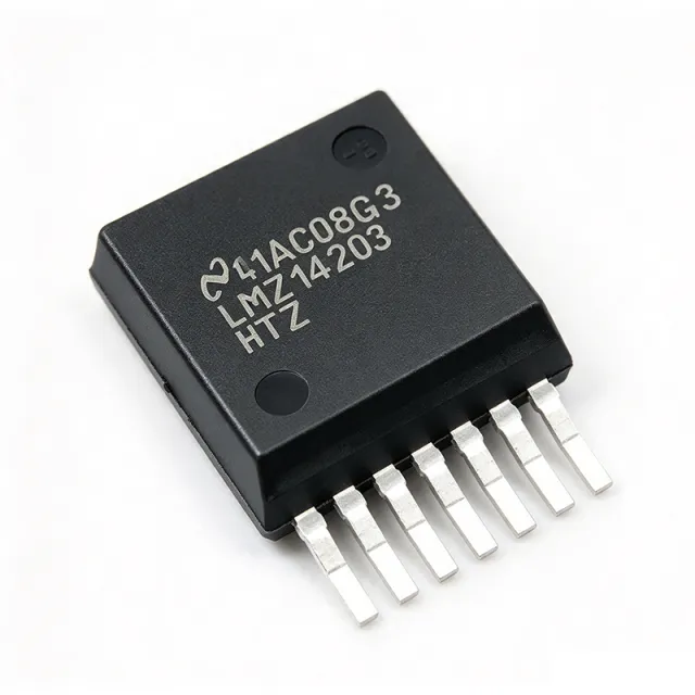
LMZ14203HTZ/NOPB - 3A 42V SIMPLE SWITCHER Power Module | TI
The Texas Instruments LMZ14203HTZ/NOPB is a SIMPLE SWITCHER 6V to 42V, 3A High Output Voltage Power Module that integrates a DC/DC buck converter, power MOSFETs, inductor, and passives into a single 7-pin TO-PMOD (NDW) surface-mount package. It delivers an adjustable output from 5V to 30V at up to 3A continuous load current with typical efficiency up to 92%, and operates across an industrial -40C to +125C junction temperature range. What is a SIMPLE SWITCHER Power Module? It is a category of complete step-down (buck) DC/DC converter modules that integrate the synchronous MOSFETs, the bootstrap diode, the power inductor, and the basic compensation network inside the IC package. Compared to a discrete buck converter that requires the designer to choose a FET, inductor, Schottky diode, and feedback loop compensation, a power module collapses all of those selections into one part, which shortens design time, reduces PCB area, and improves EMI repeatability. The LMZ14203HTZ/NOPB sits in TI's high-input-voltage, high-output-voltage SIMPLE SWITCHER family, which lives under the broader hierarchy of: non-isolated POL module -> DC/DC converter -> switching regulator -> power management IC -> semiconductor. Key features include 6V to 42V wide input range, 5V to 30V adjustable output, 3A continuous output current, integrated shielded inductor, internal MOSFETs with bootstrap diode, and internal soft-start. The module uses peak-current-mode control with internal loop compensation, eliminating the need for an external compensation network. Protection features include thermal shutdown, input under-voltage lockout, output over-voltage protection, and cycle-by-cycle current limit. The TO-PMOD (NDW) package provides low thermal resistance with a bottom-side thermal pad for PCB heatsinking. The architecture uses TI's proprietary WEBENCH-compatible SIMPLE SWITCHER topology. The internal synchronous MOSFETs eliminate the external Schottky diode required by earlier non-synchronous modules, increasing efficiency and reducing solution footprint. The integrated shielded inductor minimizes radiated EMI while maintaining a 10mm x 10mm total PCB footprint. Typical applications include industrial 24V rail point-of-load regulation, factory automation PLC I/O power, 12V/24V distributed bus stepping, telecom equipment intermediate rails, and test-and-measurement instrumentation. The wide 42V input tolerates transients on industrial 24V and 28V avionics buses. When designing with this module, the primary trade-off is solution size versus thermal performance: the integrated inductor caps switching frequency around 800 kHz, which is lower than discrete converters but eliminates the largest external component. Use the exposed thermal pad with at least 1 square inch of copper pour for 3A continuous load at VIN above 24V. This page synthesizes distributor pricing, drop-in alternatives, and practical thermal/design notes not found on the manufacturer product page alone.