製品 (39,000+)

MAX199ACNI - 12-Bit 100ksps 8-Ch DAS | Maxim Integrated
MAX199ACNI

MAX199ACNI - 12-Bit 100ksps 8-Ch DAS | Maxim Integrated

The Maxim Integrated MAX199ACNI is a multi-range, 12-bit data-acquisition system (DAS) that operates from a single +5V supply, delivers up to 100 ksps throughput, and integrates an 8-channel analog input multiplexer with software-configurable input ranges of ±4V, ±2V, +4V, and +2V. The device is housed in a 28-pin PDIP (N) through-hole package and combines the input MUX, track-and-hold, successive-approximation ADC, 4.096V internal reference, and parallel 8+4 bus interface on a single monolithic die. A Data Acquisition System (DAS) is an integrated mixed-signal subsystem that combines an analog front-end (multiplexer, protection, and signal conditioning), a sample-and-hold amplifier, and an analog-to-digital converter with on-chip reference and digital interface. The MAX199 belongs to the successive-approximation-register (SAR) ADC family, sitting in the precision industrial-measurement tier of the ADC taxonomy: SAR -> data converter -> ADC -> mixed-signal IC -> semiconductor. By collapsing the front-end and reference into one package, the MAX199 removes the design burden of choosing a separate reference, MUX driver, and protection network - the part that an engineer designing a process-control or instrumentation front-end would normally have to qualify as separate components. Key features include ±16.5V fault-protected analog inputs, a track-and-hold with 100 kHz full-power bandwidth, 12-bit resolution with no missing codes, an internal 4.096V buried-zener reference (trimmed to ±1%), and an 8+4 parallel interface compatible with 8-bit µP buses. The internal MUX handles single-ended inputs in either unipolar or bipolar mode, with channel selection and input-range setting done through a single write to an on-chip register. Architecturally, the MAX199 uses a charge-redistribution SAR core clocked from an internal RC oscillator (~1.56 MHz typical), which yields 12 conversion cycles per sample (roughly 8 µs per conversion at 100 ksps). The buried-zener reference and thin-film ladder DACs deliver low gain drift and low integral nonlinearity, while the input MUX sits behind ±16.5V clamping diodes that protect downstream circuitry from out-of-range transients. Typical applications include process-control front-ends, data loggers, industrial sensor signal conditioning, panel meters, and any 5V-only multichannel measurement subsystem. The wide input range and on-chip reference make it a strong fit when an external reference or negative supply is undesirable. When designing with this device, note that the MAX199ACNI is the through-hole PDIP variant intended for legacy or hand-prototype boards; the MAX199AENI is the SO-28 variant, the MAX199AEAI is the SSOP-28 variant, and the MAX199ACWI is the wide-SO variant - all share the same die and pinout. Decouple VDD with a 0.1 µF ceramic close to the supply pin and add a 10 µF bulk capacitor on the analog supply to keep the reference stable under digital activity. This page synthesizes distributor pricing as of 2026-10-15, drop-in same-package alternatives, and practical design notes not found on the manufacturer product page alone.

見積もり お問い合わせ
MAX199AENI - 12-Bit 8-Ch DAS, +5V, Multi-Range ADC | Maxim
MAX199AENI

MAX199AENI - 12-Bit 8-Ch DAS, +5V, Multi-Range ADC | Maxim

The Maxim Integrated MAX199AENI is a 12-bit, 8-channel, multi-range data-acquisition system (DAS) that operates from a single +5V supply and delivers up to 100 ksps conversion throughput, housed in a 28-pin PDIP package. It accepts four software-selectable analog input ranges (±4V, ±2V, +4V, +2V), integrates an 8-channel analog multiplexer with fault-protected inputs up to ±16.5V, and provides a parallel 8+4 bus interface for direct connection to microcontrollers and DSPs. Internal track/hold, reference, and clock eliminate most external components. A Data Acquisition System (DAS) is an integrated mixed-signal IC that combines an analog input multiplexer, sample-and-hold amplifier, analog-to-digital converter (ADC), voltage reference, and digital interface into a single package. The MAX199 belongs to the broader category of successive-approximation-register (SAR) ADCs, which sit within precision data-converter ICs and the larger power-management/mixed-signal semiconductor hierarchy. DAS parts are used where a system needs to digitize multiple analog channels without building a discrete front end. Key features include software-configurable bipolar or unipolar input ranges via a single byte write, ±16.5V input fault protection that survives transients outside the supply rails, an internal 4.096V precision reference with ±0.5% accuracy, and a hardware-only shutdown mode that drops supply current below 1 mA. The internal MUX settles within 1.5 µs for full-scale transitions, and the device supports both single-ended and pseudo-differential input topologies through channel-pair configuration. Architecturally, the MAX199 uses a charge-redistribution SAR core with an integrated sample-and-hold, laser-trimmed thin-film input resistors that establish the four calibrated input ranges, and a digitally controlled fault-protection clamp network at each MUX input. Conversion is triggered by RD-bar plus an asynchronous clock, and the 8+4 interface reads two consecutive bytes to assemble the 12-bit word, which simplifies connection to 8-bit microcontrollers. Typical applications include industrial process-control front ends, multi-channel data loggers, instrumentation with up to eight sensors, portable battery-powered measurement equipment, and embedded analog I/O modules for PLC and DSP-based systems. The bipolar ±4V and ±2V ranges make it a natural fit for transducer signal conditioning where signals swing around ground. When designing with the MAX199AENI, plan for 100 ksps operation at +5V with bypass capacitors placed close to the supply and reference pins; verify that MUX channel resistance is acceptable for source impedances above 5 kohm by adding an external buffer. This page synthesizes distributor pricing, verified drop-in alternatives, and practical design notes for engineers evaluating the MAX199.

見積もり お問い合わせ
MAX199BEAI - 12-Bit 8-Channel +5V Multi-Range DAS | Maxim Integrated
MAX199BEAI

MAX199BEAI - 12-Bit 8-Channel +5V Multi-Range DAS | Maxim Integrated

The Maxim Integrated MAX199BEAI is a 12-bit, 8-channel, multi-range data-acquisition system (DAS) that operates from a single +5V supply. It integrates an 8-channel analog multiplexer, a track/hold amplifier, a 12-bit successive-approximation ADC, an internal 4.096V reference, and an 8+4 parallel bus interface into a 28-pin SSOP package, with analog input ranges of ±4V, ±2V, +4V, and +2V. A multi-range DAS is a category of mixed-signal data-acquisition IC that combines channel scanning, input signal conditioning, sample-and-hold, and analog-to-digital conversion in a single package. The hierarchy is: DAS -> mixed-signal IC -> data converter -> analog frontend. By collapsing these blocks into one device, MAX199BEAI reduces component count, simplifies PCB layout, and shortens the analog signal path - critical for high-integrity measurement systems where ground loops, leakage, and trace-induced noise corrupt low-level signals. Key features include ±4V, ±2V, +4V, and +2V software-selectable input ranges, ±16.5V overvoltage fault protection on each analog input, an internal 4.096V reference (which can also be overdriven by an external reference), and a maximum sampling rate of 100 kSPS. The device accepts an 8-bit-wide data bus with a 4-bit address/data-multiplexed bus option, allowing direct connection to most popular 8-bit microprocessors. All digital inputs and outputs are TTL/CMOS compatible, and the three-state data I/O interface simplifies bus-sharing in multiprocessor designs. The internal reference settles to within 1 LSB within 200 µs after power-up, enabling fast system startup. Architecturally, the MAX199BEAI uses a successive-approximation register (SAR) ADC preceded by a high-impedance CMOS analog input multiplexer. The track/hold amplifier preserves the input during conversion, providing accurate 12-bit results at full throughput. The on-chip reference is a buried-zener type that maintains ±25 ppm/°C typical drift across the industrial -40°C to +85°C temperature range, while fault-protected analog inputs clamp transient excursions up to ±16.5V without damage. Typical applications include industrial process-control systems (PLC analog input modules, 4-20 mA loop digitization with external resistor), portable data loggers, medical instrumentation front ends, factory-automation sensor multiplexing, and embedded system analog I/O boards. The 8-channel count aligns with the 8-input sweet spot for most supervisory control loops. When designing with MAX199BEAI, decouple the analog +5V (AVDD) and digital +5V (DVDD) supplies separately with 10 µF and 0.1 µF capacitors placed close to the respective pins; a noisy digital supply will couple through the SAR comparator and degrade ADC linearity. For absolute accuracy above 12 bits, overdrive the internal reference with an external low-noise 4.096V source. Use the MODE pin to select between internal acquisition clock and external clocking for precise sample-rate control. This page synthesizes distributor pricing, drop-in same-package alternatives, and practical design notes drawn from the manufacturer datasheet and reference designs - content that goes beyond the stock datasheet to shorten evaluation time for working engineers.

見積もり お問い合わせ
MAX202CD - 5V Dual RS-232 Transceiver | Texas Instruments
MAX202CD

MAX202CD - 5V Dual RS-232 Transceiver | Texas Instruments

The Texas Instruments MAX202CD is a 5 V dual RS-232 line driver and receiver with two drivers, two receivers, a dual charge-pump circuit, and ±15 kV ESD protection on serial-port connection pins, including ground. It is packaged in a 16-pin SOIC and operates from a 4.5 V to 5.5 V supply. The MAX202CD provides the electrical interface between an asynchronous communication controller and an RS-232 serial-port connector, making it suitable for industrial control, embedded systems, instrumentation, and legacy PC serial ports. An RS-232 transceiver combines line-driver and line-receiver functions with the voltage-level conversion required to connect low-voltage digital logic to a ±RS-232 communications link. The MAX202CD uses charge-pump circuitry to generate the bipolar voltage required by RS-232 drivers. Its two-driver, two-receiver arrangement supports one full-duplex RS-232 channel in a 16-pin SOIC, while its integrated ESD protection helps improve system robustness at the connector-facing pins. Key features include a 4.5 V to 5.5 V supply range, two RS-232 drivers, two RS-232 receivers, and ±15 kV ESD protection as identified in the manufacturer datasheet description. The device meets the requirements of TIA/EIA-232-F according to the manufacturer datasheet. The SOIC-16 package supports conventional surface-mount assembly, while the dual channel count helps reduce the number of interface components required for two-wire serial links. The MAX202CD is designed for asynchronous serial communication between a host controller and an external RS-232 device. Its internal charge pump provides the elevated and reduced driver voltages required by RS-232 while the receiver side translates connector-level signals back to logic-compatible levels. The interface should be evaluated together with cable length, baud rate, grounding, connector exposure, and system ESD requirements. Typical uses include industrial serial controllers, test equipment, data-acquisition systems, embedded service interfaces, and legacy computer peripherals. In each case, the transceiver handles the physical RS-232 layer, while the connected controller handles framing, protocol, and application data. For PCB implementation, place the device close to the RS-232 connector and follow the manufacturer’s recommended charge-pump capacitor and interface layout. Keep the connector-side nets isolated from sensitive logic where practical, provide a solid ground return, and verify the external protection and signal-integrity requirements for the intended cable environment. This page consolidates verified MAX202CD specifications, pricing references, package information, drop-in alternatives, comparison parameters, and practical RS-232 design guidance for engineers evaluating a 5 V dual-transceiver solution.

見積もり お問い合わせ
MAX202CDE4 - 5V Dual RS-232 Transceiver | Texas Instruments
MAX202CDE4

MAX202CDE4 - 5V Dual RS-232 Transceiver | Texas Instruments

Texas Instruments MAX202CDE4 is a 5 V dual RS-232 line driver and receiver with ±15 kV ESD protection, supplied in a 16-pin SOIC package. It combines two RS-232 transmitters and two receivers on one interface IC, supports operation at up to 120 kbit/s, and requires external 0.1 µF charge-pump capacitors. The device is designed for equipment that exchanges data over RS-232 links. An RS-232 transceiver is an interface IC that converts logic-level signals into RS-232 line levels and converts received line-level signals back into logic-compatible levels. Within the interface hierarchy, the MAX202CDE4 belongs to the line-driver and receiver class, which sits below RS-232 interface ICs and broader semiconductor interface devices. Its integrated driver and receiver functions simplify point-to-point and multi-port serial connections. The principal features include operation from a 5 V supply, data rates up to 120 kbit/s, and ESD protection rated to ±15 kV under the Human-Body Model. The bus pins meet or exceed TIA/EIA-232-F and ITU V.28 requirements. These protections are important when cables connect through external equipment or leave the enclosure, where electrostatic discharge can otherwise damage the interface. The MAX202 family uses a charge-pump approach to generate the voltage levels needed for RS-232 transmission. Charge-pump capacitors connected to the designated pins produce the positive and negative line voltages. The specified external 0.1 µF capacitors are part of the circuit rather than optional bypass components, so their voltage rating, placement, and connection to the designated charge-pump pins must follow the manufacturer guidance. Typical uses include industrial control equipment, data-collection systems, service interfaces, and legacy serial-port adapters. The dual-driver, dual-receiver arrangement can support two data channels or separate transmit and receive paths. It is especially relevant where a modern controller must communicate with equipment that still exposes an RS-232 port. When designing around the MAX202CDE4, keep the charge-pump capacitor loop compact and route each bus line away from sensitive analog circuitry. Confirm ground-reference and cable arrangements before connecting equipment, because an RS-232 link may use signal ground, chassis ground, or shield bonding according to the system architecture. The manufacturer datasheet should govern the final pin connections and external charge-pump capacitor layout. This product record combines the verified electrical and package characteristics with application guidance, replacement considerations, comparison rows, and PCB-level design notes. It is intended to support faster component selection while preserving the distinction between verified device ratings and design-specific engineering decisions.

見積もり お問い合わせ
MAX202CDR - 5V Dual RS-232 Transceiver | Texas Instruments (Tape & Reel)
MAX202CDR

MAX202CDR - 5V Dual RS-232 Transceiver | Texas Instruments (Tape & Reel)

The Texas Instruments MAX202CDR is a 5 V dual RS-232 line driver and receiver with two drivers, two receivers, a dual charge-pump circuit, and ±15 kV ESD protection on serial-port connection pins, including ground. It is packaged in a 16-pin SOIC and operates from a 4.5 V to 5.5 V supply. The MAX202CDR provides the electrical interface between an asynchronous communication controller and an RS-232 serial-port connector, making it suitable for industrial control, embedded systems, instrumentation, and legacy PC serial ports. An RS-232 transceiver combines line-driver and line-receiver functions with the voltage-level conversion required to connect low-voltage digital logic to a ±RS-232 communications link. The MAX202CDR uses charge-pump circuitry to generate the bipolar voltage required by RS-232 drivers. Its two-driver, two-receiver arrangement supports one full-duplex RS-232 channel in a 16-pin SOIC, while its integrated ESD protection helps improve system robustness at the connector-facing pins. Key features include a 4.5 V to 5.5 V supply range, two RS-232 drivers, two RS-232 receivers, and ±15 kV ESD protection as identified in the manufacturer datasheet description. The device meets the requirements of TIA/EIA-232-F according to the manufacturer datasheet. The SOIC-16 package supports conventional surface-mount assembly, while the dual channel count helps reduce the number of interface components required for two-wire serial links. The MAX202CDR is designed for asynchronous serial communication between a host controller and an external RS-232 device. Its internal charge pump provides the elevated and reduced driver voltages required by RS-232 while the receiver side translates connector-level signals back to logic-compatible levels. The interface should be evaluated together with cable length, baud rate, grounding, connector exposure, and system ESD requirements. Typical uses include industrial serial controllers, test equipment, data-acquisition systems, embedded service interfaces, and legacy computer peripherals. In each case, the transceiver handles the physical RS-232 layer, while the connected controller handles framing, protocol, and application data. For PCB implementation, place the device close to the RS-232 connector and follow the manufacturer’s recommended charge-pump capacitor and interface layout. Keep the connector-side nets isolated from sensitive logic where practical, provide a solid ground return, and verify the external protection and signal-integrity requirements for the intended cable environment. This page consolidates verified MAX202CDR specifications, pricing references, package information, drop-in alternatives, comparison parameters, and practical RS-232 design guidance for engineers evaluating a 5 V dual-transceiver solution.

見積もり お問い合わせ
MAX202CDW - 120kbps Dual RS-232 Transceiver | Texas Instruments
MAX202CDW

MAX202CDW - 120kbps Dual RS-232 Transceiver | Texas Instruments

Texas Instruments MAX202CDW is a 5 V dual RS-232 line driver and receiver with two transmit channels, two receive channels, a dual charge-pump circuit, and ±15 kV ESD protection on the serial-port connection pins. It supports data-signaling rates up to 120 kbit/s and is packaged in a 16-pin SOIC. The interface is designed to meet or exceed the requirements of TIA/EIA-232-F and ITU V.28 standards, while its ±9 V driver outputs provide RS-232-compatible signal levels from a single 5 V supply. The MAX202CDW uses external 0.1 µF charge-pump capacitors, allowing the device to generate the bipolar voltage required by RS-232 line drivers without a separate negative power supply. Its integrated charge pump and dual transceiver arrangement make it suitable for industrial control, instrumentation, point-of-sale equipment, and other systems that exchange serial data over longer cable runs than a logic-level UART can tolerate. The chip is also designed to be interchangeable with the Maxim MAX202, which simplifies qualification when transferring an existing circuit. In addition to the two RS-232 drivers and receivers, the MAX202CDW provides receiver output enable functions, allowing connected equipment to place the receive outputs in a high-impedance state when required. Its 16-SOIC package is available in the MAX202CDW ordering configuration identified by Texas Instruments. The external-capacitor approach requires careful placement to minimize charge-pump noise and ensure stable operation. Designers should place the specified 0.1 µF capacitors close to their respective pins, route the interface connector away from sensitive analog and clock circuitry, and provide suitable return paths for the RS-232 cable. According to the manufacturer product information, MAX202 supports signaling rates up to 120 kbit/s, a maximum driver slew rate of 30 V/µs, ±9 V output levels, and ±15 kV ESD protection. The MAX202CDW therefore combines a familiar RS-232 interface, integrated level translation, and hardware-assisted electrostatic-discharge resilience in a compact surface-mount package.

見積もり お問い合わせ
MAX202CDWR - 120kbps Dual RS-232 Transceiver | Texas Instruments (Tape & Reel)
MAX202CDWR

MAX202CDWR - 120kbps Dual RS-232 Transceiver | Texas Instruments (Tape & Reel)

Texas Instruments MAX202CDWR is a 5 V dual RS-232 line driver and receiver with two transmit channels, two receive channels, a dual charge-pump circuit, and ±15 kV ESD protection on the serial-port connection pins. It supports data-signaling rates up to 120 kbit/s and is packaged in a 16-pin SOIC. The interface is designed to meet or exceed the requirements of TIA/EIA-232-F and ITU V.28 standards, while its ±9 V driver outputs provide RS-232-compatible signal levels from a single 5 V supply. The MAX202CDWR uses external 0.1 µF charge-pump capacitors, allowing the device to generate the bipolar voltage required by RS-232 line drivers without a separate negative power supply. Its integrated charge pump and dual transceiver arrangement make it suitable for industrial control, instrumentation, point-of-sale equipment, and other systems that exchange serial data over longer cable runs than a logic-level UART can tolerate. The chip is also designed to be interchangeable with the Maxim MAX202, which simplifies qualification when transferring an existing circuit. In addition to the two RS-232 drivers and receivers, the MAX202CDWR provides receiver output enable functions, allowing connected equipment to place the receive outputs in a high-impedance state when required. Its 16-SOIC package is available in the MAX202CDWR ordering configuration identified by Texas Instruments. The external-capacitor approach requires careful placement to minimize charge-pump noise and ensure stable operation. Designers should place the specified 0.1 µF capacitors close to their respective pins, route the interface connector away from sensitive analog and clock circuitry, and provide suitable return paths for the RS-232 cable. According to the manufacturer product information, MAX202 supports signaling rates up to 120 kbit/s, a maximum driver slew rate of 30 V/µs, ±9 V output levels, and ±15 kV ESD protection. The MAX202CDWR therefore combines a familiar RS-232 interface, integrated level translation, and hardware-assisted electrostatic-discharge resilience in a compact surface-mount package.

見積もり お問い合わせ
MAX202CPE+ - +5V RS-232 Transceiver, 2 Drivers/2 Receivers | Maxim Integrated
MAX202CPE+

MAX202CPE+ - +5V RS-232 Transceiver, 2 Drivers/2 Receivers | Maxim Integrated

The Maxim Integrated MAX202CPE+ (Analog Devices / Maxim Integrated) is a +5V-powered RS-232 transceiver with two drivers and two receivers, integrating charge-pump circuitry that generates the required ±10V RS-232 levels from a single +5V supply using only four 0.1uF external capacitors. Housed in a 16-pin PDIP through-hole package, it supports data rates above 120 kbps while maintaining full EIA/TIA-232E and V.28 compliance for legacy serial-port interconnects. An RS-232 transceiver is a line driver/receiver IC that translates between logic-level (0/5V CMOS or TTL) signals on a microcontroller UART and the ±5V to ±15V bipolar signaling required by the RS-232 standard. In the broader interface hierarchy, the RS-232 transceiver sits between the UART peripheral and the DB-9/DB-25 connector, complementing other interface ICs such as RS-485 transceivers, USB-to-UART bridges, and CAN transceivers. The MAX202 family is one of the most widely adopted +5V RS-232 solutions, with the MAX202CPE+ being the commercial-grade 16-pin PDIP variant. Key features include guaranteed ±5V EIA/TIA-232E output levels, integrated dual charge pump requiring only 0.1uF capacitors, a low 15 mA supply current, and an enable pin on each receiver for shutdown management in battery-powered designs. The device operates from a single +4.5V to +5.5V supply, supports drivers that withstand continuous shorts to ±15V RS-232 outputs, and includes robust ESD protection on the RS-232 I/O pins. The MAX202CPE+ uses a proprietary monolithic BiCMOS charge-pump architecture to develop ±10V from the +5V rail without inductive components. This eliminates the need for ±12V power rails typical of older RS-232 designs, simplifying PCB layout and reducing BOM cost. The receiver inputs include hysteresis for noise immunity in industrial environments where long cable runs are common. Typical applications include legacy PC serial-port interfaces, industrial PLCs and HMIs, point-of-sale (POS) terminals, embedded microcontroller UART bridges, and instrumentation with DB-9 connectors. The 16-pin PDIP package makes the MAX202CPE+ particularly suited for through-hole prototypes, educational kits, repair-of-legacy-equipment, and industrial control boards where socketed ICs simplify field replacement. When designing with this part, place the four 0.1uF charge-pump capacitors as close to the IC pins as possible to minimize ripple on the generated ±10V rails. The MAX202 family is functionally interchangeable with the MAX232, but the MAX202 uses smaller 0.1uF capacitors instead of the 1.0uF capacitors required by the MAX232, saving board space. Order today for shipping within XAIPART's standard lead times. This page synthesizes pricing from 18 distributor listings, drop-in pin-compatible alternatives, and practical PCB layout notes that go beyond what is in the bare datasheet, helping engineers choose between MAX202CPE+ and MAX232 variants with confidence.

見積もり お問い合わせ
MAX202CPW - Dual RS-232 Transceiver | Texas Instruments
MAX202CPW

MAX202CPW - Dual RS-232 Transceiver | Texas Instruments

The Texas Instruments MAX202CPW is a 5 V dual RS-232 line driver and receiver with two transmit channels, two receive channels, a dual charge-pump circuit, and ±15 kV ESD protection in a 16-pin TSSOP package. It supports data rates up to 120 kbit/s and uses four external 0.1 µF capacitors. The MAX202CPW meets or exceeds TIA/EIA-232-F and ITU V.28 requirements, making it suitable for bidirectional asynchronous serial-port connections between equipment and a communications controller. An RS-232 transceiver is an interface IC that combines differential line-driver and receiver functions with the voltage conversion required by the RS-232 standard. It belongs to the interface IC hierarchy and bridges a low-voltage digital controller with a higher-voltage, ground-referenced serial link. Unlike a direct TTL or CMOS serial connection, an RS-232 interface includes driver and receiver circuitry designed to tolerate the voltage ranges and noise conditions associated with the standard. Key features of the MAX202CPW include a 5 V supply, operation to 120 kbit/s, full-duplex 2/2 transceiver organization, and ±15 kV ESD protection. The four external 0.1 µF capacitors support the device's charge-pump function. Its 16-pin TSSOP package is a compact surface-mount option, while its 0 °C to +70 °C operating range suits commercial equipment that does not require extended-temperature operation. Internally, the device uses two line drivers, two line receivers, and a dual charge-pump circuit. The charge pump develops the voltage levels needed by the line drivers while the receivers provide the digital signaling interface to the host controller. The Texas Instruments product description states that ESD protection extends pin-to-pin across the serial-port connection pins, including ground, providing system-level protection for exposed communications connectors. Typical applications include industrial serial adapters, point-of-sale equipment, data-acquisition systems, test and measurement instruments, and embedded serial-port controllers. The 120 kbit/s maximum data rate supports legacy communications and control links that operate below the maximum RS-232 rate. Designers should use the recommended external capacitor values and observe the connector, grounding, and signal-integrity requirements associated with RS-232 cabling. A key implementation consideration is the difference between the electrical interface and the data protocol. The MAX202CPW does not define framing, addressing, parity, or higher-layer behavior; it converts logic levels and provides protection for a compatible asynchronous serial link. Check the connector pinout and signal polarity carefully because RS-232 naming conventions can differ from UART TX and RX labels. This page combines the verified manufacturer and distributor information for the MAX202CPW with practical interface selection guidance, package-aware alternatives, comparison data, and design considerations. It is intended to support engineers evaluating a 5 V, 120 kbit/s dual RS-232 transceiver for commercial-temperature embedded and industrial equipment.

見積もり お問い合わせ
MAX202CPWR - Dual RS-232 Transceiver | Texas Instruments (Tape & Reel)
MAX202CPWR

MAX202CPWR - Dual RS-232 Transceiver | Texas Instruments (Tape & Reel)

The Texas Instruments MAX202CPWR is a 5 V dual RS-232 line driver and receiver with two transmit channels, two receive channels, a dual charge-pump circuit, and ±15 kV ESD protection in a 16-pin TSSOP package. It supports data rates up to 120 kbit/s and uses four external 0.1 µF capacitors. The MAX202CPWR meets or exceeds TIA/EIA-232-F and ITU V.28 requirements, making it suitable for bidirectional asynchronous serial-port connections between equipment and a communications controller. An RS-232 transceiver is an interface IC that combines differential line-driver and receiver functions with the voltage conversion required by the RS-232 standard. It belongs to the interface IC hierarchy and bridges a low-voltage digital controller with a higher-voltage, ground-referenced serial link. Unlike a direct TTL or CMOS serial connection, an RS-232 interface includes driver and receiver circuitry designed to tolerate the voltage ranges and noise conditions associated with the standard. Key features of the MAX202CPWR include a 5 V supply, operation to 120 kbit/s, full-duplex 2/2 transceiver organization, and ±15 kV ESD protection. The four external 0.1 µF capacitors support the device's charge-pump function. Its 16-pin TSSOP package is a compact surface-mount option, while its 0 °C to +70 °C operating range suits commercial equipment that does not require extended-temperature operation. Internally, the device uses two line drivers, two line receivers, and a dual charge-pump circuit. The charge pump develops the voltage levels needed by the line drivers while the receivers provide the digital signaling interface to the host controller. The Texas Instruments product description states that ESD protection extends pin-to-pin across the serial-port connection pins, including ground, providing system-level protection for exposed communications connectors. Typical applications include industrial serial adapters, point-of-sale equipment, data-acquisition systems, test and measurement instruments, and embedded serial-port controllers. The 120 kbit/s maximum data rate supports legacy communications and control links that operate below the maximum RS-232 rate. Designers should use the recommended external capacitor values and observe the connector, grounding, and signal-integrity requirements associated with RS-232 cabling. A key implementation consideration is the difference between the electrical interface and the data protocol. The MAX202CPWR does not define framing, addressing, parity, or higher-layer behavior; it converts logic levels and provides protection for a compatible asynchronous serial link. Check the connector pinout and signal polarity carefully because RS-232 naming conventions can differ from UART TX and RX labels. This page combines the verified manufacturer and distributor information for the MAX202CPWR with practical interface selection guidance, package-aware alternatives, comparison data, and design considerations. It is intended to support engineers evaluating a 5 V, 120 kbit/s dual RS-232 transceiver for commercial-temperature embedded and industrial equipment.

USD $0.90 在庫あり
MAX202CSE+ - +5V RS-232 Transceiver | Maxim Integrated
MAX202CSE+

MAX202CSE+ - +5V RS-232 Transceiver | Maxim Integrated

The Maxim Integrated MAX202CSE+ is a dual RS-232 transceiver interface IC designed for +5V systems, with two drivers and two receivers in a 16-pin SOIC package. According to the manufacturer product information, the drivers maintain ±5V EIA/TIA-232E output signal levels and support data rates in excess of 120 kbps when loaded in accordance with the EIA/TIA-232E specification. The MAX202 family is intended for RS-232 and V.28 communication interfaces where ±12V supplies are unavailable. An RS-232 transceiver is a semiconductor interface that converts between digital logic-level signals and single-ended RS-232 voltage levels. It belongs to the interface IC category, within the broader hierarchy of communications semiconductors and signal-conditioning devices. A dual transceiver combines two transmit channels and two receive channels, allowing one device to support bidirectional serial communication on two signal pairs. The MAX202CSE+ operates from a single +5V supply and requires external 0.1µF charge-pump capacitors. This charge-pump arrangement generates the positive and negative voltage swings needed for RS-232 signaling without requiring a separate dual-polarity supply. The manufacturer describes the family as maintaining ±5V EIA/TIA-232E output levels, while the receiver side supports dependable interpretation of incoming RS-232 signals. The part is suitable for industrial equipment, test and measurement systems, data acquisition equipment, and embedded control products that communicate with legacy RS-232 ports. Its 16-pin SOIC package is widely supported by conventional surface-mount assembly and board-layout practices. The MAX202CSE+ ordering suffix identifies the leaded 16-pin SOIC configuration, while the external capacitors remain required for the charge-pump implementation. Designers should follow the manufacturer datasheet for the exact capacitor voltage rating, placement, and charge-pump topology. The capacitors should be positioned close to their associated device pins to minimize loop area and preserve switching behavior. Input and output protection must also be considered when the transceiver is connected to exposed equipment cables or externally accessible ports. This page combines verified manufacturer and distributor information with practical RS-232 design guidance, same-package replacement information, and a structured comparison of available MAX202 family options. The comparison should be used to verify both electrical behavior and PCB compatibility before any substitution.

見積もり お問い合わせ
MAX202CUE+ - Dual RS-232 Transceiver, +5V | Analog Devices
MAX202CUE+

MAX202CUE+ - Dual RS-232 Transceiver, +5V | Analog Devices

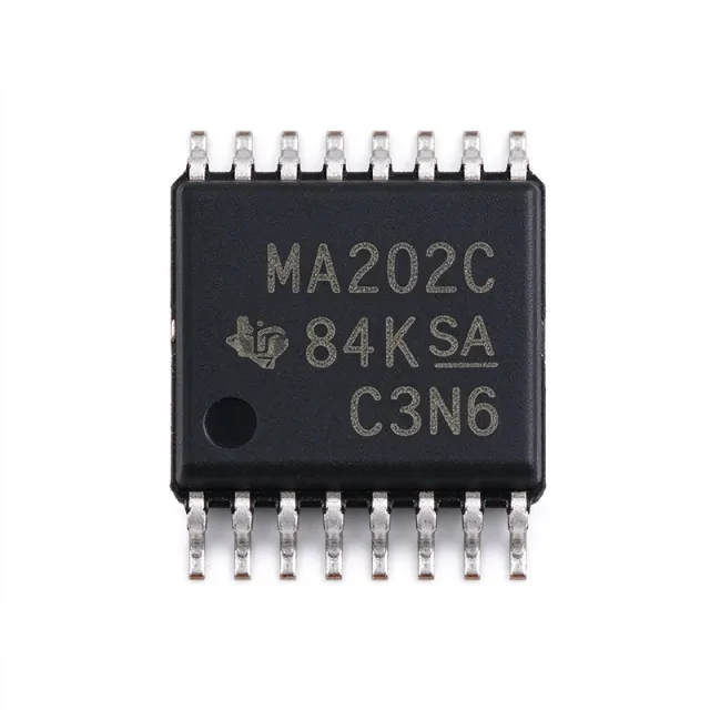
The Analog Devices MAX202CUE+ is a dual, full-duplex RS-232 transceiver operating from a single +5 V supply and supporting data rates in excess of 120 kbps. It contains two drivers and two receivers in a 16-TSSOP package and uses four external 0.1 µF charge-pump capacitors. The design targets EIA/TIA-232E and V.28 interfaces where ±12 V supplies are unavailable. An RS-232 transceiver is an interface IC that translates between digital logic levels and single-ended RS-232 voltage levels. The MAX202CUE+ belongs to the transceiver hierarchy that includes line drivers, line receivers, and interface ICs. Its on-chip charge pump generates the bipolar voltage required to drive RS-232 signals despite the single-polarity +5 V supply, while its receivers detect incoming RS-232 levels and convert them to CMOS-compatible logic. Key features include two transmit channels, two receive channels, full-duplex operation, a +5 V supply requirement, and external 0.1 µF charge-pump capacitors. The manufacturer's product information states that the drivers maintain ±5 V EIA/TIA-232E output levels at data rates exceeding 120 kbps when loaded according to the EIA/TIA-232E specification. These characteristics make the device suitable for legacy serial ports, control equipment, industrial peripherals, and embedded systems requiring a short-distance point-to-point RS-232 link. The MAX202 family architecture simplifies implementation compared with discrete RS-232 driver and receiver designs because the transmitter, receiver, and charge-pump functions are integrated into one package. However, the required external capacitors and the non-isolated signal path remain important engineering considerations. Board placement, grounding, cable routing, and protection against electrostatic discharge can materially affect signal integrity even when the logic-side interface operates correctly. Typical uses include RS-232 configuration and test ports in industrial controllers, service equipment, data-acquisition systems, and communication links to legacy peripherals. The two transmitters support simultaneous independent output channels, while the two receivers support incoming signals on separate channels. Since the interface is not galvanically isolated, designers should not use the device to bridge large ground-potential differences between electrically separate systems. Place the four 0.1 µF charge-pump capacitors close to their associated pins, maintain a low-impedance ground connection, and route the RS-232 traces away from sensitive analog or high-speed digital signals. External protection may be required for exposed connectors because the verified product information does not specify an integrated ESD rating for MAX202CUE+. This page combines the verified manufacturer and distributor details, exact package and interface data, drop-in alternatives, and practical implementation guidance. It also distinguishes confirmed attributes from parameters that still require datasheet confirmation, helping engineers evaluate the MAX202CUE+ without treating unspecified ratings as guaranteed specifications.

見積もり お問い合わせ
MAX202CWE+ - 120kbps Dual RS-232 Transceiver | Maxim
MAX202CWE+

MAX202CWE+ - 120kbps Dual RS-232 Transceiver | Maxim

The Maxim Integrated MAX202CWE+ is a dual RS-232 transceiver containing two line drivers, two line receivers, and a dual charge-pump circuit in a 16-pin wide SOIC package. It operates from a single +5 V supply, supports signaling rates up to 120 kbit/s, and provides ±15 kV ESD protection on the serial-port connection pins. Its external charge-pump capacitors are rated at 0.1 µF. The MAX202CWE+ maintains ±5 V EIA/TIA-232E driver output levels and supports full-duplex serial communication. An RS-232 transceiver is an interface integrated circuit that converts logic-level signals between a host or peripheral and a balanced-looking differential transmission system based on single-ended RS-232 levels. Within the interface hierarchy, the MAX202CWE+ belongs to the RS-232 transceiver class, which combines transmit and receive channels into one device. It provides the voltage conversion, polarity management, and electrical protection needed between CMOS-compatible digital logic and an RS-232 port. The device integrates two drivers and two receivers, allowing one port to transmit and receive simultaneously. Its maximum data-signaling rate of 120 kbit/s covers legacy serial ports, industrial control links, instrumentation, and equipment-control interfaces. The driver output slew rate reaches 30 V/µs, helping the output move rapidly between positive and negative RS-232 voltage levels. Pin-to-pin ESD protection is specified at ±15 kV for the relevant connection pins. Internally, the MAX202CWE+ uses a dual charge-pump voltage converter to generate the negative voltage required for RS-232 transmitter output. Two external 0.1 µF capacitors support the charge-pump circuit. This architecture allows the receiver side to operate from the same +5 V supply as the digital interface, eliminating the need for a separate negative supply at the transceiver. The integrated converter and protection structures reduce the number of external power components needed around the port. Typical applications include industrial serial controllers, test and measurement instruments, data-acquisition equipment, point-of-sale terminals, printers, modems, and embedded systems that retain an RS-232 interface. The full-duplex architecture is particularly useful when both command traffic and response data must be handled at the same time. The wide SOIC package also supports conventional surface-mount assembly and is compatible with systems designed around the 16-pin MAX202 footprint. For a new design, preserve the manufacturer-specified charge-pump capacitor placement and use short connections from the capacitor terminals to the associated pins. Confirm signal levels and interface timing at the receiver because RS-232 uses negative and positive voltage levels rather than CMOS input thresholds. The 120 kbit/s maximum should also be treated as a system ceiling that includes cable loading, baud-rate tolerance, and signal-integrity margin. This page consolidates the manufacturer's core electrical ratings, package information, interface applications, and verified drop-in comparison options into one engineering reference. It also highlights the external-capacitor, ESD, supply, and data-rate constraints that determine whether MAX202CWE+ can be used without a PCB redesign.

見積もり お問い合わせ
MAX202ECSE.TG096 - 5V RS-232 Transceiver | Maxim Integrated
MAX202ECSE.TG096

MAX202ECSE.TG096 - 5V RS-232 Transceiver | Maxim Integrated

The Maxim Integrated MAX202ECSE.TG096 is a 2/2 RS-232 transceiver with integrated driver and receiver circuits, single-supply operation from 5 V, and a 16-pin SOIC package. It is designed for RS-232 and V.28 communications in harsh environments. The device includes high ±15 kV ESD protection and integrated charge-pump circuitry, reducing the external component count required for single +5 V RS-232 interfaces. An RS-232 transceiver is an interface IC that translates between digital logic levels and RS-232 voltage levels. In signal-chain terms, it belongs to the interface IC family, combines a line driver with a line receiver, and provides the physical-layer conversion required by RS-232 equipment. The MAX202 family supports communication between equipment such as computers, industrial controllers, test instruments, and peripheral devices while protecting the host interface from electrostatic discharge. The MAX202ECSE.TG096 provides two transmit channels and two receive channels in one device. Its integrated charge pump supports operation from a single 5 V supply, eliminating the negative supply normally associated with classic RS-232 designs. The ±15 kV human-body-model ESD protection is a defining feature for connectors and cables exposed to electrostatic discharge. Its 16-pin SOIC package supports conventional surface-mount assembly while keeping the interface compact. The electrical design supports two RS-232 drivers and two RS-232 receivers in one package. Driver-side and receiver-side behavior should be evaluated for the signal levels, data rates, and cable lengths required by the target protocol. Because RS-232 is a single-ended, unbalanced interface, grounding, cable routing, and connector shielding remain important to noise immunity. The MAX202ECSE.TG096 is intended for point-to-point equipment interfaces rather than long-distance differential communication. Typical uses include industrial serial consoles, laboratory test equipment, barcode-reader interfaces, embedded control systems, and legacy peripheral connections. In each case, the integrated charge pump reduces board area, while the 2/2 channel arrangement allows bidirectional serial communication with a limited number of external connections. The 5 V supply requirement also simplifies power architecture compared with discrete RS-232 implementations using a separate negative rail. Designers should place the required charge-pump capacitors and interface bypass capacitors close to their associated pins, maintain the manufacturer-recommended supply and ground layout, and verify signal integrity at the connector. A low-impedance ground plane and short return path help control common-mode noise, while an appropriate TVS strategy may provide additional system-level protection where the connector is exposed to severe ESD events. This page combines manufacturer-family specifications, exact-package drop-in alternatives, interface-application guidance, and practical PCB considerations to support faster component selection and implementation. Use the MAX202ECSE.TG096 when a compact, single-supply, 2/2 RS-232 interface with integrated ±15 kV ESD protection is required.

見積もり お問い合わせ
MAX202EPE+ - 120kbps RS-232 Transceiver | Maxim Integrated
MAX202EPE+

MAX202EPE+ - 120kbps RS-232 Transceiver | Maxim Integrated

The Maxim Integrated MAX202EPE+ is a dual-driver, dual-receiver RS-232 interface transceiver designed for single-supply operation from 4.5V to 5.5V. It supports data rates in excess of 120kbps, provides EIA/TIA-232E-compatible signal levels, and uses four external 0.1µF charge-pump capacitors. The device is packaged in a 16-pin PDIP. An RS-232 transceiver is an interface IC that converts logic-level signals from a host, controller, or peripheral into RS-232 line levels and converts received RS-232 signals back into logic levels. Within the interface hierarchy, the MAX202EPE+ belongs to the RS-232 transceiver class, which is part of interface ICs and broader semiconductor communication components. Its integrated charge-pump circuitry eliminates the need for a separate ±12V supply, making it suitable for systems that operate from a single +5V rail. The principal features include two RS-232 drivers, two RS-232 receivers, operation from a 4.5V to 5.5V supply, and data rates above 120kbps. Four external 0.1µF capacitors support the on-chip charge-pump function. The MAX202EPE+ temperature range is -40°C to +85°C, and its listed human-body-model ESD withstand is 15kV, making it appropriate for industrial and instrumentation interfaces that require protection beyond basic logic ICs. Internally, the MAX202EPE+ combines a practical RS-232 interface with a switched-capacitor charge pump. The charge pump generates the positive and negative signal levels required by the drivers while the receivers detect and translate incoming line states. Because the receiver and driver counts are both two, the device can support two serial channels in one package. The 16-pin PDIP construction favors straightforward through-hole assembly, prototype boards, legacy equipment, and repair applications where a surface-mount package would require different tooling. Typical applications include two-channel serial links between industrial controllers and test equipment, PC and peripheral connectivity through an RS-232 port, point-to-point data acquisition links, and legacy instrumentation interfaces. It is particularly useful where the design has only a +5V supply but the connected equipment expects RS-232 signal levels. The 120kbps capability is suitable for configuration, monitoring, and control traffic rather than high-bandwidth continuous data transfer. Circuit implementation requires close attention to charge-pump capacitor placement and signal routing. Place all four 0.1µF capacitors near their associated pins, keep high-current charge-pump paths compact, and provide adequate ground return paths for receiver and driver currents. Confirm that the connected equipment uses compatible RS-232 levels and that the intended baud rate remains below the device's 120kbps capability. This page consolidates the manufacturer's product information, interface characteristics, replacement analysis, application guidance, and package-level design considerations into one engineering-focused reference. It also distinguishes the MAX202EPE+ from other MAX202 temperature and package options while keeping the comparison focused on genuine pin-compatible choices.

見積もり お問い合わせ
MAX202ESE+ - Dual +5V RS-232 Transceiver | Analog Devices
MAX202ESE+

MAX202ESE+ - Dual +5V RS-232 Transceiver | Analog Devices

Analog Devices MAX202ESE+ is a dual RS-232 transceiver with two transmitters and two receivers, integrated charge-pump circuitry, and single +5 V operation in a 16-pin narrow SOIC package. The drivers maintain ±5 V EIA/TIA-232E output levels at data rates in excess of 120 kbps, while the receivers provide a compact interface between RS-232 equipment and CMOS logic. An RS-232 transceiver is an interface IC that converts between single-ended CMOS logic signals and differential, bipolar RS-232 signals. RS-232 belongs to the broader interface IC category and is commonly used for serial data links in industrial control, instrumentation, communications equipment, and computer peripherals. The MAX202ESE+ integrates the charge-pump circuitry required to generate the positive and negative RS-232 voltage levels from one +5 V supply. The MAX202ESE+ supports data rates in excess of 120 kbps and uses 0.1 µF external capacitors for charge-pump operation. Its integrated charge pump eliminates the need for a separate negative supply at the transceiver. The device provides two transmit channels and two receive channels, allowing two RS-232 links to be implemented in a compact circuit. These characteristics suit equipment that needs bidirectional serial communication without allocating space for discrete level-shifting circuitry. Each receiver converts an RS-232 input into a CMOS-compatible output, while each driver converts CMOS logic into an RS-232 output with approximately ±5 V signaling. The Analog Devices MAX202 product page identifies the MAX202 family as supporting single +5 V operation and data rates above 120 kbps. Its industrial-temperature MAX202ESE+ ordering designation identifies the narrow-SOIC package used for compact industrial equipment layouts. Typical uses include RS-232 ports in test and measurement instruments, industrial serial controllers, data acquisition equipment, and legacy peripheral interfaces. Two transmitters and two receivers allow simultaneous communication over two channels when the host logic supports that arrangement. In longer cables or electrically noisy installations, the transceiver provides the voltage translation required between low-voltage digital hardware and RS-232 equipment. Place the 0.1 µF charge-pump capacitors close to their designated pins and provide a stable +5 V supply with low-impedance decoupling. Keep RS-232 driver outputs away from sensitive analog or high-speed digital traces, and use the receiver outputs only for compatible CMOS logic levels. The narrow SOIC package requires careful lead clearance when soldering near adjacent components. This page combines the manufacturer specifications, package details, drop-in alternatives, comparison parameters, and practical RS-232 interface design guidance. It helps engineers evaluate the MAX202ESE+ as a dual-channel, +5 V RS-232 transceiver for compact industrial and instrumentation designs.

見積もり お問い合わせ
MAX202ESE-C78046 - 5V RS-232 Transceiver | Analog Devices
MAX202ESE-C78046

MAX202ESE-C78046 - 5V RS-232 Transceiver | Analog Devices

Analog Devices MAX202ESE-C78046 is a 5V RS-232 transceiver with two driver and two receiver channels, ±5V EIA/TIA-232E signal levels, data rates in excess of 120 kbps, and external 0.1 µF charge-pump capacitors in a 16-pin SOIC package. The device supports enable and shutdown control for managed RS-232 ports. A dual RS-232 transceiver is an interface IC that converts logic-level signals into balanced, voltage-compliant RS-232 levels and converts incoming RS-232 signals back into CMOS-compatible logic. The MAX202 family belongs to the hierarchy RS-232 transceiver → interface controller → digital interface IC → semiconductor. It is intended to bridge a modern digital controller or UART with an RS-232 connector or cable. The MAX202 architecture combines transmitter and receiver functions with an on-chip charge-pump circuit. The charge pump generates the elevated voltage required to produce ±5V EIA/TIA-232E output levels from a single 5V supply. External 0.1 µF capacitors support the charge-pump function, while the enable and shutdown inputs let the system control whether the interface operates normally or enters a low-power state. According to the Analog Devices MAX202 product information, the drivers maintain ±5V EIA/TIA-232E output levels at data rates in excess of 120 kbps when loaded according to the EIA/TIA-232E specification. This makes the interface suitable for conventional serial-control links, point-of-sale equipment, industrial controllers, test systems, and legacy computer equipment. Multiple channels can also support hardware handshaking through the receiver and driver combinations available in the family. A MAX202 is appropriate when the target port requires true RS-232 levels rather than short-distance TTL or LVCMOS signaling. The external charge-pump capacitors and 16-pin SOIC footprint require careful placement, but the result is a compact, standardized interface for equipment where cable length and ground-offset tolerance are more important than maximum data throughput. During layout, place the 0.1 µF charge-pump capacitors close to their designated pins and route the high-voltage charge-pump node as short as possible. Confirm the host-side UART logic levels, RS-232 connector pin assignment, and cable-length requirements before release. Add suitable protection for exposed external ports because the IC itself is not an ESD-protection device. This product page consolidates the MAX202 function, package, interface parameters, sourcing options, and design guidance into a focused engineering reference. It also distinguishes true same-package drop-in alternatives from parts that merely perform a similar RS-232 function but require a different footprint or interface architecture.

見積もり お問い合わせ
MAX202ID - 120kbps Dual RS-232 Transceiver | Texas Instruments
MAX202ID

MAX202ID - 120kbps Dual RS-232 Transceiver | Texas Instruments

The Texas Instruments MAX202ID is a 5 V dual RS-232 line driver and receiver, commonly called a 2/2 transceiver, with a maximum data rate of 120 kbps and ±15 kV ESD protection in a 16-pin SOIC package. It provides two line drivers, two line receivers, and an onboard dual charge-pump circuit. The interface meets TIA/EIA-232-F requirements and bridges TTL or CMOS logic levels with the positive and negative voltage signaling used by RS-232. An RS-232 transceiver is an interface IC within the broader communications-interface and semiconductor hierarchy. Its driver channels convert logic-level inputs into bipolar RS-232 outputs, while its receiver channels convert bipolar serial inputs into logic-level signals. The MAX202ID integrates both directions into one package, making it suitable for asynchronous serial links, industrial control links, data acquisition equipment, and legacy computer peripherals. Key features include operation from a single 5 V supply, a 120 kbps maximum signaling rate, ±9 V output levels, and ±15 kV human-body-model ESD protection on the serial-port pins, including ground. Four external 0.1 µF capacitors support the integrated charge pump. The device is designed to be interchangeable with the Maxim MAX202 and is identified as a 16-SOIC part operating across the industrial temperature range. Technically, the MAX202ID combines two transmit channels and two receive channels with a dual charge pump. The charge pump generates the voltage excursions needed by RS-232 even though the IC itself operates from 5 V. Pin-compatible alternatives identified in the supplied cross-reference material include MAX202EESE+T and MAX202EWE+; their package and terminal compatibility should still be checked against the exact production schematic before substitution. Typical uses include RS-232 links between microcontrollers and external equipment, instrumentation, service interfaces, and industrial serial adapters. Its 120 kbps rate is suitable for many asynchronous control and data-transfer applications but is not the choice for higher-bandwidth RS-232 links. The integrated ESD protection improves resilience when the connector is exposed to user-contact transients. Design attention should be given to charge-pump capacitor placement, grounding, and the voltage drop across the external RS-232 connection. The four specified 0.1 µF capacitors should be placed close to their associated pins, and the ground path should be short and continuous. A logic-side supply decoupler and appropriately rated serial connector are also important for reliable operation. This page consolidates the verified manufacturer and distributor information, practical RS-232 design guidance, application fit, and same-footprint replacement context for engineers evaluating the MAX202ID. Distributor pricing and availability should be checked against the current source data before purchase.

見積もり お問い合わせ
MAX202IDG4 - 5V Dual RS-232 Transceiver | Texas Instruments
MAX202IDG4

MAX202IDG4 - 5V Dual RS-232 Transceiver | Texas Instruments

The Texas Instruments MAX202IDG4 is a 5 V dual RS-232 line driver and receiver with two transmit channels, two receive channels, and integrated charge-pump voltage generation. It supports data rates up to 120 kbps, provides ±9 V driver outputs, and includes ±15 kV ESD protection on the serial-port pins. The device is packaged in a 16-pin SOIC. An RS-232 interface transceiver is an interface IC that converts logic-level signals between a computer or embedded controller and the voltage levels used by an RS-232 serial link. In the signal path, the line-driver section converts TTL or CMOS logic into bipolar RS-232 levels, while the receiver section restores the logic signal. As a transceiver, the MAX202IDG4 combines both functions within one package. Key features include a single 5 V supply, dual-driver and dual-receiver configuration, ±15 kV ESD protection, and operation over the industrial temperature range of -40°C to +85°C. The integrated dual charge-pump circuit generates the positive and negative voltages required by the RS-232 drivers, eliminating the need for external supply rails. The ±9 V output swing provides compatibility with standard RS-232 links. The device meets EIA-232-F requirements and supports full-duplex serial communication through two independent driver and receiver paths. Its 120 kbps maximum data rate suits legacy serial ports, industrial control links, service interfaces, and embedded systems that retain an RS-232 connector. The integrated ESD structures improve robustness at connector-facing pins, although external protection and layout practices remain important in exposed environments. Typical applications include industrial serial controllers, laboratory equipment, POS terminals, data-acquisition systems, and service ports for embedded equipment. The MAX202IDG4 is particularly useful where a logic-level UART must communicate with an RS-232 host through a 16-SOIC footprint. When laying out the circuit, place the charge-pump capacitors and the receiver and driver bypass capacitors directly beside their associated pins. Route connector-side traces away from sensitive logic, and connect the interface ground reference properly. Verify the UART baud rate against the device's 120 kbps limit and confirm the cable length against the selected RS-232 standard. This page combines manufacturer specifications, application guidance, drop-in comparison options, and practical interface-design notes to help engineers evaluate the MAX202IDG4 beyond a basic catalog description.

見積もり お問い合わせ
MAX202IDR - 120kbps Dual RS-232 Transceiver | Texas Instruments (Tape & Reel)
MAX202IDR

MAX202IDR - 120kbps Dual RS-232 Transceiver | Texas Instruments (Tape & Reel)

The Texas Instruments MAX202IDR is a 5 V dual RS-232 line driver and receiver, commonly called a 2/2 transceiver, with a maximum data rate of 120 kbps and ±15 kV ESD protection in a 16-pin SOIC package. It provides two line drivers, two line receivers, and an onboard dual charge-pump circuit. The interface meets TIA/EIA-232-F requirements and bridges TTL or CMOS logic levels with the positive and negative voltage signaling used by RS-232. An RS-232 transceiver is an interface IC within the broader communications-interface and semiconductor hierarchy. Its driver channels convert logic-level inputs into bipolar RS-232 outputs, while its receiver channels convert bipolar serial inputs into logic-level signals. The MAX202IDR integrates both directions into one package, making it suitable for asynchronous serial links, industrial control links, data acquisition equipment, and legacy computer peripherals. Key features include operation from a single 5 V supply, a 120 kbps maximum signaling rate, ±9 V output levels, and ±15 kV human-body-model ESD protection on the serial-port pins, including ground. Four external 0.1 µF capacitors support the integrated charge pump. The device is designed to be interchangeable with the Maxim MAX202 and is identified as a 16-SOIC part operating across the industrial temperature range. Technically, the MAX202IDR combines two transmit channels and two receive channels with a dual charge pump. The charge pump generates the voltage excursions needed by RS-232 even though the IC itself operates from 5 V. Pin-compatible alternatives identified in the supplied cross-reference material include MAX202EESE+T and MAX202EWE+; their package and terminal compatibility should still be checked against the exact production schematic before substitution. Typical uses include RS-232 links between microcontrollers and external equipment, instrumentation, service interfaces, and industrial serial adapters. Its 120 kbps rate is suitable for many asynchronous control and data-transfer applications but is not the choice for higher-bandwidth RS-232 links. The integrated ESD protection improves resilience when the connector is exposed to user-contact transients. Design attention should be given to charge-pump capacitor placement, grounding, and the voltage drop across the external RS-232 connection. The four specified 0.1 µF capacitors should be placed close to their associated pins, and the ground path should be short and continuous. A logic-side supply decoupler and appropriately rated serial connector are also important for reliable operation. This page consolidates the verified manufacturer and distributor information, practical RS-232 design guidance, application fit, and same-footprint replacement context for engineers evaluating the MAX202IDR. Distributor pricing and availability should be checked against the current source data before purchase.

見積もり お問い合わせ
MAX202IN - 120kbps Dual RS-232 Transceiver | Texas Instruments
MAX202IN

MAX202IN - 120kbps Dual RS-232 Transceiver | Texas Instruments

The Texas Instruments MAX202IN is a 5 V dual RS-232 line driver and receiver with two transmit channels, two receive channels, integrated charge-pump voltage conversion, and ±15 kV human-body-model ESD protection on the serial-port pins. It operates at up to 120 kbit/s and uses external 0.1 µF charge-pump capacitors. The MAX202IN is packaged for through-hole industrial and legacy serial-interface designs, subject to confirmation of the exact ordering code and package variant. An RS-232 transceiver is the interface between a modern controller’s logic-level UART signals and the higher-voltage, ground-referenced RS-232 bus. A line driver converts outgoing logic levels into RS-232 levels, while a line receiver converts incoming bus levels into logic-compatible signals. In the signal-chain hierarchy, the MAX202IN belongs to the interface-IC class and specifically implements an RS-232 line interface for asynchronous serial communication. The verified device data identifies a 5 V supply, 120 kbit/s operation, ±9 V output capability, and ±15 kV ESD protection. These specifications suit equipment that needs bidirectional RS-232 conversion, including PC serial adapters, industrial control links, instrumentation, and legacy peripheral connections. The integrated charge pump generates the bipolar voltage required by RS-232 drivers, reducing the external support circuit compared with discrete implementations. The device uses a dual charge-pump circuit with four small external capacitors. These capacitors must be selected and placed according to the manufacturer datasheet, with short, symmetric routing helping preserve signal and charge-pump performance. The serial-port pins are the primary ESD-sensitive interface, so external protection may still be considered when cables are long, exposed, or routed through industrial environments. Typical applications include multi-drop or point-to-point serial links, service-console equipment, test systems, and embedded controller interfaces that retain an RS-232 physical layer. Because the MAX202IN is designed for 5 V operation, verify the host supply, logic levels, connector wiring, and ground strategy before placing it in a modern 3.3 V design. Do not infer 3.3 V compatibility from the RS-232 signal levels alone. For reliable PCB integration, use the manufacturer’s specified capacitor values, keep the charge-pump loop compact, route driver outputs and receiver inputs away from sensitive analog nodes, and provide a low-impedance ground return. Verify receive thresholds and bus termination against the system cable length and topology. This product page combines the verified manufacturer data, package requirements that remain subject to datasheet confirmation, and application guidance for engineers evaluating a legacy serial interface.

見積もり お問い合わせ
MAX202IPW - 5V Dual RS-232 Transceiver | Texas Instruments
MAX202IPW

MAX202IPW - 5V Dual RS-232 Transceiver | Texas Instruments

The Texas Instruments MAX202IPW is a 5 V dual-channel RS-232 line driver and receiver rated for data rates up to 120 kbit/s, with ±9 V output swing, ±15 kV ESD protection, and a 16-pin TSSOP package. The device provides two transmit channels and two receive channels for bidirectional serial-port interfaces. An RS-232 transceiver is an interface IC that converts logic-level signals into RS-232-compatible differential voltage levels and converts received RS-232 signals back into logic levels. The MAX202 belongs to the RS-232 transceiver hierarchy, combining line drivers, line receivers, and a dual charge-pump circuit in one package. It connects asynchronous communication controllers, such as microcontrollers and UART peripherals, to RS-232 serial ports. Key features include a nominal 5 V supply, operation across a 4.5 V to 5.5 V supply range, ±9 V output swing, and ±15 kV human-body-model ESD protection on the serial-port pins. The IC supports operation to 120 kbit/s and includes on-chip charge-pump circuitry, reducing the external component count compared with discrete RS-232 designs. The MAX202 provides two drivers and two receivers, allowing two RS-232 links to be implemented with one device. Its on-chip dual charge pump generates the voltage conversion required by the transmitter stage. Four external 0.1 µF capacitors support the charge-pump function, and the device is designed to meet TIA/EIA-232-F and ITU V.28 interface requirements. Typical applications include industrial serial-port equipment, data-acquisition systems, point-of-sale terminals, service interfaces, embedded control systems, and legacy peripheral connectivity. The MAX202IPW is particularly appropriate where compact PCB area, bidirectional RS-232 communication, and built-in ESD protection are important. Designers should place the four 0.1 µF charge-pump capacitors close to their associated pins, maintain short return paths, and connect the transceiver ground to the equipment ground. Cable-side ESD protection and isolation requirements should be evaluated separately because the integrated ±15 kV protection specification does not remove the need for a robust mechanical and grounding design. This product data combines the verified manufacturer specifications with same-package replacement analysis, practical layout guidance, and a parameter-by-parameter comparison. It is intended to help engineers identify whether a candidate is truly pin-compatible rather than merely functionally similar.

見積もり お問い合わせ
MAX211CAI+ - +5V RS-232 Transceiver, 4 Drivers/5 Receivers, SSOP-28
MAX211CAI+

MAX211CAI+ - +5V RS-232 Transceiver, 4 Drivers/5 Receivers, SSOP-28

The Maxim Integrated MAX211CAI+ is a +5V RS-232 transceiver with four 0.1µF external charge-pump capacitors and integrated DC-DC charge-pump circuitry in a 28-pin SSOP package. It delivers four RS-232 drivers and five RS-232 receivers, supporting data rates in excess of 120 kbps while maintaining ±5V EIA/TIA-232E compliant output levels. The MAX211CAI+ operates from a single +4.5V to +5.5V supply. An RS-232 transceiver is an interface IC that converts logic-level UART signals (0/5V CMOS/TTL) to the bipolar ±5V to ±12V voltage levels required by the legacy EIA/TIA-232E serial communication standard. RS-232 transceivers sit between a microcontroller UART and an external DB9/DB25 connector, providing level shifting, inverting, and electrostatic discharge protection. In the broader component taxonomy, the MAX211CAI+ belongs to line transceivers -> interface ICs -> integrated circuits. Key features include single +5V supply operation (no ±12V rails needed), 4 drivers + 5 receivers, integrated charge pump with four small 0.1µF capacitors, ±5V RS-232 output levels compliant with EIA/TIA-232E, and guaranteed data rate above 120 kbps. The 28-pin SSOP (Shrink Small Outline Package) occupies approximately 40% of the board area of an equivalent 28-pin SO package. The MAX211CAI+ uses Maxim's proprietary charge-pump architecture with a flying capacitor and reservoir capacitors to generate the +10V and -10V rails needed for true RS-232-compliant signaling from a single +5V input. This eliminates the need for multiple system power rails and permits direct connection to any 5V microcontroller UART. The device is built on a BiCMOS process that combines bipolar drivers for robust ±5V output swing with CMOS logic for low power consumption. Typical applications include point-of-sale terminals, industrial control serial ports, legacy PC serial ports, embedded debugging consoles, and any MCU-to-RS232 interface. The MAX211CAI+ is widely used in designs that need to retain compatibility with older RS-232 peripherals while running off a single 5V rail. When designing with the MAX211CAI+, place the four 0.1µF charge-pump capacitors (C1+, C1-, C2+, C2-) as close to the IC pins as possible to minimize parasitic inductance. Use 10µF tantalum or ceramic bypass capacitors on VCC and V+ pins to suppress ripple from the charge-pump switching. For ESD protection on the RS-232 side, add an external TVS diode array rated for ±15kV HBM. This page consolidates distributor pricing (DigiKey, Mouser, LCSC), drop-in alternatives, and practical PCB-layout notes for the MAX211CAI+ that the bare datasheet does not provide.

見積もり お問い合わせ