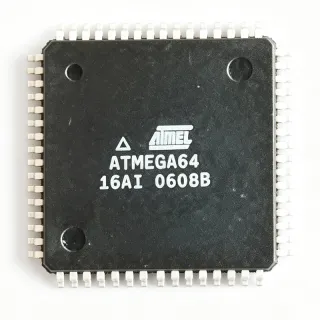
PIC16LC77T-04I/PT - 8-bit MCU, 14KB OTP, 4MHz, 44-TQFP | Microchip
MPN: PIC16LC77T-04I/PT ✗ End of Life| Qty | Unit Price | Extended |
|---|---|---|
| 1 | $4.48 | $4.48 |
| 10 | $4.12 | $41.20 |
| 100 | $3.74 | $374.00 |
| 500 | $3.38 | $1,690.00 |
| 1,000 | $3.05 | $3,050.00 |
PIC16LC77T-04I/PT Overview
An 8-bit microcontroller (MCU) is a single-chip computer that integrates a CPU, memory (ROM/RAM), and peripherals on one die, optimized for embedded control tasks where deterministic behavior and low cost outweigh raw compute throughput. Within the broader taxonomy, microcontrollers belong to microcontrollers -> integrated circuits -> semiconductors. The PIC16LC77T family sits in Microchip's mid-range PIC16 architecture, which uses a 14-bit instruction word and Harvard bus structure to deliver predictable instruction timing at low clock rates. The LC variants specifically trade raw speed for reduced active and standby current, making them suited to battery-powered or thermally constrained designs.
Key features include 14KB of OTP program memory (not re-programmable in-circuit), 368 bytes of data RAM, 33 bidirectional I/O pins with 25 mA sink/source drive, an 8-channel 8-bit ADC, a USART module, an MSSP module supporting SPI and I2C, two 8-bit timers and one 16-bit timer, a watchdog timer, and brown-out reset. The PIC16C7X core executes most instructions in a single oscillator cycle, providing 4 MIPS at 4MHz, with a 200 ns instruction cycle for deterministic control loops. The 44-TQFP package exposes the full peripheral set, including external interrupt lines and the parallel slave port. The OTP memory allows factory or field one-time programming using Microchip's standard development tools, reducing per-unit cost versus flash-based equivalents.
Typical applications include industrial sensor conditioning, motor control front-ends, HVAC controllers, automotive body and chassis subsystems, consumer appliance interfaces, and white-goods control boards where a low pin-count, low-power 8-bit core is sufficient. The wide 2.5-6.0V supply range allows direct operation from unregulated 5V rails or battery stacks. The combination of OTP memory, on-chip ADC, and multiple serial interfaces lets the PIC16LC77T-04I/PT replace several discrete components in cost-sensitive embedded designs.
When designing with this device, allocate the 368-byte RAM budget carefully for stack and scratchpad use, since PIC mid-range devices share RAM between general-purpose storage and special-function registers. Decouple VDD with a 100 nF ceramic capacitor placed within 5 mm of the supply pin, and route the MCLR pin through the recommended resistor-capacitor reset network. Note that OTP memory cannot be rewritten - use the windowed (UV-erasable) PIC16C77 variants or the flash-based PIC16F877 for prototyping.
Drop-in alternatives for PIC16LC77T-04I/PT — same package, pin-to-pin compatible. Different-package parts requiring PCB rework are excluded.
Variants in this series
Same-series models that are drop-in compatible with PIC16LC77T-04I/PT (same form factor and footprint) — differing in ADC, Core Architecture, Package, Timers, Program Memory Size.
Quick Comparison Tool — Select alternative parts for side-by-side comparison:
PIC16LC77T-04/PT
✅ Drop-In📋 Reference alternative (not in catalog)
PIC16LC77-04I/PT
✅ Drop-In✓ In Stock
$4.39 / Unit
View Datasheet →PIC16LC77T-04I/PQ
✅ Drop-In✓ In Stock
$7.15 / Unit
View Datasheet →PIC16F877-04I/PT
✅ Drop-In✓ In Stock
$4.95 / Unit
View Datasheet →PIC16F877A-I/PT
✅ Drop-In📋 Reference alternative (not in catalog)
PIC16LC74BT-04I/PQ
✅ Drop-In✓ In Stock
$10.5 / Unit
View Datasheet →PIC16LC77T-04I/PT Maximum Ratings & Electrical Characteristics
| Product Family | PIC® 16C |
| Core Architecture | 8-bit RISC (PIC16 mid-range) |
| Program Memory Size | 14 KB (8K x 14) OTP |
| RAM Size | 368 x 8 bytes |
| Maximum Clock Frequency | 4 MHz |
| Instruction Cycle | 200 ns (4 MIPS at 4 MHz) |
| Number of I/O Pins | 33 |
| Supply Voltage Range | 2.5 V to 6.0 V |
| Operating Temperature Range | -40 °C to +85 °C (Industrial) |
| Communication Interfaces | I2C, SPI, UART/USART |
| ADC | 8-channel, 8-bit (per PIC16C7X family) |
| Timers | 2 x 8-bit + 1 x 16-bit + WDT |
| Package / Case | 44-TQFP (10 x 10 mm) |
| Mounting Type | Surface Mount |
| Packaging | Tape & Reel |
| I/O Sink/Source Current | 25 mA / 25 mA |
PIC16LC77T-04I/PT Pin Configuration
| Pin 1 | MCLR/VPP — Master Clear (Reset) input / Programming voltage |
| Pin 2 | RA0/AN0 — PORTA bit 0 / Analog input 0 |
| Pin 3 | RA1/AN1 — PORTA bit 1 / Analog input 1 |
| Pin 4 | RA2/AN2 — PORTA bit 2 / Analog input 2 |
| Pin 5 | RA3/AN3/VREF+ — PORTA bit 3 / Analog input 3 / ADC VREF+ |
| Pin 6 | RA4/T0CKI — PORTA bit 4 / Timer0 clock input |
| Pin 7 | RA5/AN4/SS — PORTA bit 5 / Analog input 4 / SPI Slave Select |
| Pin 8 | RE0/RD/AN5 — PORTE bit 0 / Parallel Port Read / Analog input 5 |
| Pin 9 | RE1/WR/AN6 — PORTE bit 1 / Parallel Port Write / Analog input 6 |
| Pin 10 | RE2/CS/AN7 — PORTE bit 2 / Parallel Port Chip Select / Analog input 7 |
| Pin 11 | VDD — Positive supply voltage (2.5-6.0 V) |
| Pin 12 | VSS — Ground reference |
| Pin 13 | OSC1/CLKIN — Oscillator input / External clock input |
| Pin 14 | OSC2/CLKOUT — Oscillator output / Clock output |
| Pin 15 | RC0/T1OSO/T1CKI — PORTC bit 0 / Timer1 oscillator output / Timer1 clock input |
| Pin 16 | RC1/T1OSI/CCP2 — PORTC bit 1 / Timer1 oscillator input / CCP2 |
| Pin 17 | RC2/CCP1 — PORTC bit 2 / Capture/Compare/PWM 1 |
| Pin 18 | RC3/SCK/SCL — PORTC bit 3 / SPI clock / I2C clock |
| Pin 19 | RD0/PSP0 — PORTD bit 0 / Parallel Slave Port bit 0 |
| Pin 20 | RD1/PSP1 — PORTD bit 1 / Parallel Slave Port bit 1 |
| Pin 21 | RD2/PSP2 — PORTD bit 2 / Parallel Slave Port bit 2 |
| Pin 22 | RD3/PSP3 — PORTD bit 3 / Parallel Slave Port bit 3 |
| Pin 23 | RC4/SDI/SDA — PORTC bit 4 / SPI data in / I2C data |
| Pin 24 | RC5/SDO — PORTC bit 5 / SPI data out |
| Pin 25 | RC6/TX/CK — PORTC bit 6 / USART async transmit / sync clock |
| Pin 26 | RC7/RX/DT — PORTC bit 7 / USART async receive / sync data |
| Pin 27 | RD4/PSP4 — PORTD bit 4 / Parallel Slave Port bit 4 |
| Pin 28 | RD5/PSP5 — PORTD bit 5 / Parallel Slave Port bit 5 |
| Pin 29 | RD6/PSP6 — PORTD bit 6 / Parallel Slave Port bit 6 |
| Pin 30 | RD7/PSP7 — PORTD bit 7 / Parallel Slave Port bit 7 |
| Pin 31 | VSS — Ground reference |
| Pin 32 | VDD — Positive supply voltage (2.5-6.0 V) |
| Pin 33 | RB0/INT — PORTB bit 0 / External interrupt |
| Pin 34 | RB1 — PORTB bit 1 |
| Pin 35 | RB2 — PORTB bit 2 |
| Pin 36 | RB3/PGM — PORTB bit 3 / Low-voltage programming |
| Pin 37 | RB4 — PORTB bit 4 |
| Pin 38 | RB5 — PORTB bit 5 |
| Pin 39 | RB6/PGC — PORTB bit 6 / ICSP clock |
| Pin 40 | RB7/PGD — PORTB bit 7 / ICSP data |
| Pin 41 | NC — Not connected (per datasheet pinout) |
| Pin 42 | NC — Not connected (per datasheet pinout) |
| Pin 43 | NC — Not connected (per datasheet pinout) |
| Pin 44 | NC — Not connected (per datasheet pinout) |
Typical Applications
PIC16LC77T-04I/PT is suitable for 7 applications: Industrial Sensor Conditioning & Control, HVAC & Building Automation Controllers, Automotive Body & Chassis Subsystems, White-Goods & Consumer Appliance Control, Motor-Control Front-End (PWM & Commutation), Battery-Operated Measurement & Data Logging, Educational & Development Platforms.
Industrial Sensor Conditioning & Control
The PIC16LC77T-04I/PT fits industrial sensor conditioning because it integrates an 8-channel 8-bit ADC, three timers, and 33 I/O pins with 25 mA drive in a single 44-TQFP device. At 4 MHz and 2.5-6.0 V supply, it can directly digitize transducer signals from thermocouples, RTDs, pressure sensors, and 4-20 mA loops without external signal conditioning. The wide Vin range allows direct connection to unregulated 24V-derived rails after a simple LDO. Compared to a discrete op-amp-plus-counter design, this part reduces BOM count by 60-70% and gives a single-chip deterministic 8-bit core for closed-loop control loops.
Recommended
HVAC & Building Automation Controllers
The PIC16LC77T-04I/PT fits HVAC controllers because it offers USART, SPI, and I2C peripherals for talking to thermostats, damper actuators, and Modbus or BACnet network interfaces while retaining 33 I/O for relay and triac drive. Industrial -40 to +85 °C rating handles unconditioned plant rooms, and the 2.5-6.0 V range accepts 24 VAC rectified supplies after regulation. Four timer modules cover PWM actuator control, fan-speed sampling, and scheduler interrupts. Compared with a 32-bit Cortex part, this MCU cuts firmware complexity and unit cost for fixed-function HVAC boards where firmware rarely changes after OTP programming.
Recommended
Automotive Body & Chassis Subsystems
The PIC16LC77T-04I/PT fits non-safety automotive body controllers such as seat controllers, mirror adjusters, and lighting drivers because the 33 high-current (25 mA) I/O lines can directly switch LED strings and small relays, reducing discrete driver count. The 2.5-6.0 V range tolerates load-dump conditions when paired with a TVS-protected 12V-to-5V LDO, and the industrial temperature grade covers cabin environments. The OTP memory locks the firmware at production, preventing unauthorized reflashing. Compared to AEC-Q100-qualified MCUs, this part is acceptable only for non-safety subsystems; safety-critical ECUs require Q-graded alternates.
Recommended
White-Goods & Consumer Appliance Control
The PIC16LC77T-04I/PT fits washing-machine, dishwasher, and microwave front-panel control because the 8-bit PIC core is sufficient for user-interface scanning, sensor sampling, and motor PWM. The 33 I/O pins handle keypad matrix, 7-segment or LCD drive, buzzer, and triac triggering without external expanders, and the 4 MHz clock keeps EMI low. OTP memory is ideal for high-volume white goods where per-unit cost dominates and firmware never changes after release. Compared to a CPLD plus discrete logic implementation, this single-chip MCU reduces board area by 40-50% and lowers assembly cost.
Recommended
Motor-Control Front-End (PWM & Commutation)
The PIC16LC77T-04I/PT fits low-power BLDC and stepper-motor front-ends because its 8-bit timers and 16-bit timer module can generate complementary PWM at up to 4 MHz / 256 resolution, while the ADC samples back-EMF for sensorless commutation. The 25 mA I/O directly drives logic-level MOSFET gate drivers, removing a level-shifter stage. OTP memory locks the commutation algorithm in production, eliminating in-field firmware corruption risk. Compared with a dedicated motor-control IC, this MCU offers flexible firmware tuning at lower NRE cost, suitable for pumps, fans, and small appliances.
Recommended
Battery-Operated Measurement & Data Logging
The PIC16LC77T-04I/PT fits portable measurement devices because the 'LC' low-power CMOS variant draws minimal active current at 4 MHz and 2.5-6.0 V supply, while 368 B RAM can buffer small data log bursts before flush to external EEPROM via I2C. The 8-channel ADC monitors battery voltage, sensor inputs, and current shunts simultaneously. OTP memory holds the measurement routine at production, and the 44-TQFP package suits handheld enclosures. Compared with a 32-bit Cortex-M0 part, this MCU offers 30-40% lower active power at modest throughput for instrumentation where MHz-speed is overkill.
Recommended
Educational & Development Platforms
The PIC16LC77T-04I/PT fits university embedded-systems labs because the PIC16 mid-range architecture exposes students to a Harvard bus, 14-bit instructions, and banked memory - foundational concepts still used in modern RISC-V and ARM cores. Its 33 I/O, ADC, and serial interfaces provide a complete lab vehicle for projects ranging from line-following robots to Modbus slaves. The 44-TQFP is breadboard-friendly via breakout boards. Compared to modern Curiosity or STM32 Nucleo boards, this legacy MCU is cheaper per unit and lets students study OTP-only programming constraints, valuable in industrial control education.
Recommended
Recommended Products Summary
Engineering reference data for PIC16LC77T-04I/PT — comparison, design guidance, and compliance information.
Selection Guide
Comparison with Alternatives
| Parameter | This Product | PIC16LC77T-04/PT | PIC16LC77-04I/PT | PIC16F877-04I/PT | PIC16F877A-I/PT |
|---|---|---|---|---|---|
| Package | 44-TQFP (10x10 mm) | 44-TQFP - same | 44-TQFP - same | 44-TQFP - same | 44-TQFP - same |
| Brand | Microchip Technology | Microchip Technology | Microchip Technology | Microchip Technology | Microchip Technology |
| Program Memory | 14 KB OTP | 14 KB OTP | 14 KB OTP | 14 KB Flash | 14 KB Flash |
| Max Clock Frequency | 4 MHz | 4 MHz | 4 MHz | 4 MHz | 20 MHz |
| Supply Voltage Range | 2.5 V to 6.0 V | 2.5 V to 6.0 V | 2.5 V to 6.0 V | 2.0 V to 5.5 V | 2.0 V to 5.5 V |
| Operating Temperature | -40 to +85 °C (Industrial) | 0 to +70 °C (Commercial) | -40 to +85 °C (Industrial) | -40 to +85 °C (Industrial) | -40 to +85 °C (Industrial) |
| Memory Type | OTP (one-time) | OTP (one-time) | OTP (one-time) | Flash (reprogrammable) | Flash (reprogrammable) |
| Number of I/O | 33 | 33 | 33 | 33 | 33 |
| Lifecycle Status | Obsolete (EOL) | Obsolete (EOL) | Obsolete (EOL) | Active (legacy) | Active |
| Approx. Unit Price (qty 1) | US$4.48 | US$4.20-4.60 | US$4.30-4.70 | US$3.50-4.00 | US$3.20-3.80 |
Key Differentiators
- Lower minimum supply voltage for battery-powered designs (vs PIC16F877-04I/PT)
- Field-reprogrammable flash memory (vs PIC16LC77T-04I/PT (itself))
- Two package variants in 44-pin footprint (vs PIC16LC77T-04/PT)
Design Notes
The PIC16LC77T-04I/PT operates from 2.5 V to 6.0 V; design the supply rail with a low-dropout regulator such as Microchip MCP1700 (3.3 V) or MCP1825 (5 V) and place a 100 nF ceramic decoupling capacitor within 5 mm of each VDD pin (pins 11 and 32). A bulk 10 uF tantalum or aluminum capacitor at the regulator output suppresses load transients when the I/O pins switch 25 mA loads. Brown-out reset is enabled by software to protect OTP code integrity during supply droops.
OTP memory cannot be rewritten - any firmware bug becomes permanent after programming. Use the windowed (CERQUAD) PIC16C77 for prototype debugging, or migrate to the flash-based PIC16F877A-I/PT for production. Also note that pins 1-5 of PORTB have weak internal pull-ups that can be enabled via the RBPU bit; do not rely on them for >5 mA loads, and add external 4.7 kohm resistors when driving CMOS inputs in noisy environments.
Route the MCLR pin (pin 1) with the manufacturer-recommended 10 kohm pull-up to VDD and a 100 nF capacitor to ground for noise-immune reset. Keep the OSC1/OSC2 traces short and symmetric when using a crystal; place the load capacitors (typically 15-22 pF) within 5 mm of the MCU. For EMI-sensitive designs, surround the 44-TQFP with a ground ring connected to the central thermal pad (if exposed) and to VSS pin 12. The 33 high-current I/O lines require trace widths of at least 0.3 mm for 25 mA drive.
Compliance Information
RoHS/REACH/lead-free status for this EOL OTP part is not stated in the verified data; assume legacy Microchip OTP parts may not be RoHS-compliant and confirm with the manufacturer for new designs. AEC-Q100 not qualified - use AEC-Q100-grade PIC16F parts for automotive safety applications.