РЧ-трансиверы
Товары (235)

STM32WBA65RIV6 - BLE 5.4 802.15.4 MCU 2MB Flash | ST
The STMicroelectronics STM32WBA65RIV6 is an ultra-low-power multiprotocol wireless microcontroller featuring an Arm Cortex-M33 core with TrustZone and FPU running at 100 MHz, 2 Mbytes of Flash memory, an integrated 2.4 GHz radio compliant with Bluetooth LE 5.4 and IEEE 802.15.4-2015, packaged in a 68-pin VFQFPN with exposed pad. A wireless MCU (microcontroller unit) combines a general-purpose processor, memory, and a radio transceiver on one die, sitting within the hierarchy of embedded processors: MCU -> Arm Cortex-M-based MCU -> wireless SoC -> multiprotocol connectivity IC. Wireless MCUs eliminate the complexity and power cost of a discrete radio-plus-MCU two-chip solution, and the STM32WBA6xxx series is STMicroelectronics' flagship ultra-low-power entry in this class, targeting Bluetooth LE, Zigbee, and Thread mesh networks on a single silicon platform. Key differentiating features include the 100 MHz Cortex-M33 with hardware TrustZone security and FPU, 2 Mbytes of embedded Flash for large application and stack footprints, an ultra-low-power radio supporting Bluetooth SIG Low Energy specification 5.4 and IEEE 802.15.4-2015 (Zigbee and Thread), and independent power domains including a dedicated supply input for the 2.4 GHz radio and an analog independent supply for ADC and comparators. The family offers four packages from 48 to 121 pins, with or without an integrated SMPS option for extended battery life. Architecturally, the device uses ST state-of-the-art patented radio technology with a dedicated 2.4 GHz radio core, allowing concurrent multiprotocol operation and secure over-the-air updates. TrustZone-based isolation partitions secure and non-secure firmware, supporting PSA-aligned security architectures common in smart-home and industrial sensor ecosystems. Typical applications include Zigbee and Thread smart-home devices (sensors, lighting, actuators), Bluetooth LE accessories such as beacons and wearables, and industrial 802.15.4 mesh nodes where ultra-low average current determines battery replacement intervals. Design consideration: plan the RF matching network and power supply partitioning early - the dedicated RADIO supply input and exposed pad require a solid ground pour for RF performance, and the SMPS versus LDO supply variant affects layout and efficiency trade-offs. This page synthesizes distributor pricing, family drop-in variants, comparison data, and practical design notes not found on a single manufacturer datasheet page. Pricing references are as of 2026-09-13.

STM32WL55CCU6 - Dual-core Arm Cortex-M4/M0+ LoRa SoC | STMicroelectronics
The STMicroelectronics STM32WL55CCU6 is a wireless system-on-chip (SoC) that integrates a dual-core Arm Cortex-M4 and Cortex-M0+ processor with a sub-GHz radio supporting LoRa, (G)FSK, (G)MSK, and BPSK modulations. It is housed in a 48-pin UFQFPN package (7x7 mm) and operates over a supply voltage range of 1.8V to 3.6V. The device features 256 KB of flash memory and 64 KB of SRAM, making it suitable for battery-powered IoT applications. A wireless MCU is a microcontroller that integrates a radio transceiver on the same chip, enabling wireless communication without external RF components. The STM32WL55CCU6 belongs to the STM32WL series, which is part of the broader STM32 family of 32-bit microcontrollers. This SoC combines the processing power of an Arm Cortex-M4 core with the energy efficiency of a Cortex-M0+ core, allowing for flexible task partitioning and low-power operation. Key features include a maximum CPU frequency of 48 MHz for both cores, a sub-GHz radio with sensitivity down to -137 dBm (LoRa), and support for LoRaWAN and Sigfox protocols. The device also includes a rich set of peripherals such as 12-bit ADC, DAC, comparators, timers, SPI, I2C, USART, and a random number generator. The integrated radio eliminates the need for an external transceiver, reducing BOM cost and PCB area. The STM32WL55CCU6 is built on ST's low-power process technology, offering multiple low-power modes including Sleep, Stop, and Standby, with current consumption as low as 1.62 uA in Standby mode with RTC. The dual-core architecture allows the Cortex-M0+ to handle radio communication while the Cortex-M4 runs application code, optimizing power and performance. Typical applications include smart agriculture sensors, smart metering, asset tracking, smart city infrastructure, and industrial monitoring. The sub-GHz radio provides long-range communication with low power consumption, making it ideal for battery-operated devices that need to transmit data over kilometers. When designing with this device, ensure proper antenna matching and RF layout to achieve optimal radio performance. The device supports a wide operating temperature range of -40C to +85C, suitable for outdoor and industrial environments.
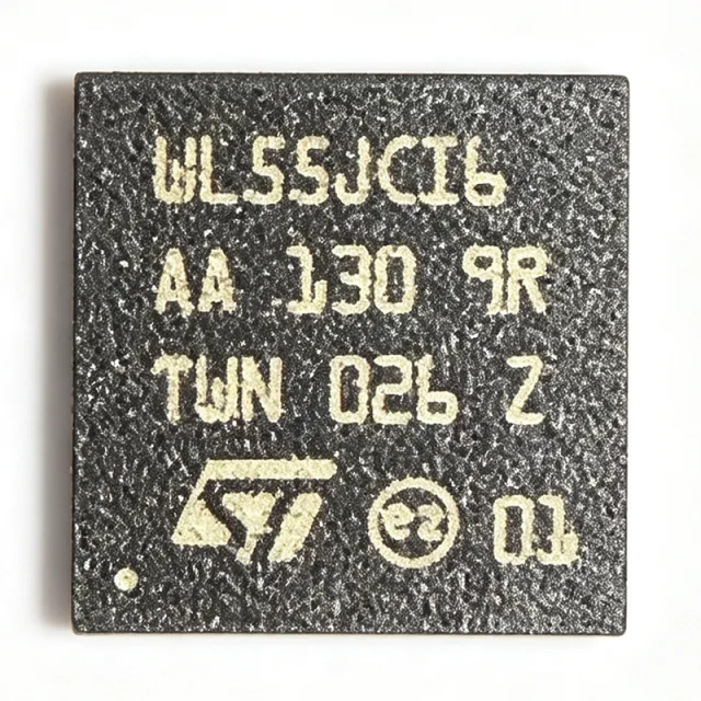
STM32WL55JCI6 - Dual-Core LoRa SoC 150-960MHz | ST
The STMicroelectronics STM32WL55JCI6 is a dual-core (Arm Cortex-M4 + Cortex-M0+) multiprotocol LPWAN wireless SoC with 256 KB flash, 64 KB SRAM, and an integrated sub-GHz radio covering 150 MHz to 960 MHz, housed in a 73-pin UFBGA package (7x7 mm). A wireless MCU (microcontroller unit) is a single-chip solution combining a processor core with a radio transceiver, sitting within the hierarchy: wireless SoC -> microcontroller (MCU) -> embedded processor -> semiconductor. The STM32WL55JCI6 belongs to the STM32WL family within the broader STM32 portfolio from STMicroelectronics, integrating the radio and application processor in one device to reduce board space, bill-of-materials cost, and design complexity compared with discrete MCU-plus-radio solutions. Key features include a 64 MHz Cortex-M4 application core with FPU and DSP instructions, a 48 MHz Cortex-M0+ core dedicated to radio protocol management, and support for LoRa, (G)FSK, (G)MSK, and BPSK modulations with LoRaWAN 1.0, Sigfox, and 802.15.4 protocol stacks. Radio sensitivity reaches -137 dBm and output power up to +22 dBm, enabling multi-kilometer links in open field. Technically, the device uses a low-power process with multiple power modes: Standby current is as low as 1.62 uA with RTC running, RX current is 4.82 mA, and TX current is 87 mA at +14 dBm. Peripherals include a 12-bit ADC, DAC, comparators, op-amps, multiple UART/SPI/I2C interfaces, and a true random number generator (TRNG) for security. Supply voltage spans 1.8V to 3.6V over -40C to +85C. Typical applications are smart agriculture sensors, smart metering (gas, water, electricity), asset tracking, industrial monitoring, and smart-city LPWAN infrastructure, where long range and battery life dominate requirements. Design tip: let the M0+ core run the radio stack while the M4 runs application code, and invest early in antenna matching and RF layout; use the STM32CubeWL package for rapid development. This page adds value beyond the datasheet by synthesizing distributor pricing, drop-in same-package alternatives, design notes, and an AEO-optimized FAQ for AI search citation.

STM32WLE5C8 - 32-bit Arm Cortex-M4 LoRa SoC | STMicroelectronics
The STM32WLE5C8 is a 32-bit Arm Cortex-M4 microcontroller with integrated LoRa transceiver from STMicroelectronics, designed for long-range, low-power wireless applications. It operates at a maximum CPU frequency of 48 MHz and features 256 KB of flash memory and 64 KB of SRAM. The device is housed in a 48-pin UFQFPN package (7x7 mm) and supports a supply voltage range of 1.8V to 3.6V. A microcontroller unit (MCU) is a compact integrated circuit designed to govern a specific operation in an embedded system. It contains a processor core, memory, and programmable input/output peripherals. The STM32WLE5C8 belongs to the STM32WL family, which combines an MCU with a sub-GHz radio transceiver, enabling single-chip solutions for IoT devices. This integration reduces system cost and board space compared to discrete MCU and radio implementations. Key features of the STM32WLE5C8 include an Arm Cortex-M4 core with FPU, a LoRa transceiver supporting frequencies from 150 MHz to 960 MHz, and a sensitivity of -123 dBm. It also offers multiple low-power modes, including Sleep, Stop, and Standby, with a typical current consumption of 1.4 uA in Standby mode. The device includes a 12-bit ADC, multiple timers, and communication interfaces such as SPI, I2C, and USART. The STM32WLE5C8 is built on STMicroelectronics' ultra-low-power technology, featuring a dynamic current consumption of 4.6 mA in active mode at 48 MHz. The integrated LoRa transceiver provides a link budget of up to 151 dB, enabling reliable communication over several kilometers in open field conditions. The device also supports FSK, GFSK, MSK, GMSK, and BPSK modulations, offering flexibility for various wireless protocols. Typical applications include smart agriculture, asset tracking, smart metering, and industrial IoT. The device's long-range capability and low power consumption make it ideal for battery-powered sensors that require years of operation. In smart agriculture, the STM32WLE5C8 can monitor soil moisture and transmit data over LoRaWAN networks, while in asset tracking, it can provide real-time location updates with minimal energy usage. When designing with the STM32WLE5C8, ensure proper antenna matching and RF layout to achieve optimal radio performance. The device requires a 32 MHz crystal for the radio and a 32.768 kHz crystal for the RTC. Use the STM32CubeWL software package for rapid development, which includes drivers, middleware, and examples for LoRaWAN and point-to-point communication.
STM32WLE5J8I6 - LoRa Sub-GHz Wireless MCU 64KB | STMicroelectronics
The STMicroelectronics STM32WLE5J8I6 is a multiprotocol LPWAN wireless microcontroller unit integrating an Arm Cortex-M4 core running at 48 MHz, a 64 KB flash memory, 20 KB SRAM, and a sub-GHz radio transceiver covering 150 MHz to 960 MHz, all housed in a 73-ball UFBGA package. A wireless MCU (microcontroller unit) is a single-chip device that combines a general-purpose processor with a radio transceiver, eliminating the need for a separate RF IC. Within the power/semiconductor hierarchy, the STM32WLE5J8I6 sits under the STM32WL series, which belongs to the 32-bit Arm Cortex-M4 microcontroller family, the wireless MCU category, and the broader semiconductor device ecosystem for long-range IoT connectivity. Key differentiating features include support for LoRa, (G)FSK, (G)MSK, and BPSK modulation schemes, an ultra-low-power architecture engineered for battery-powered LPWAN nodes, and a supply voltage range of 1.8 V to 3.6 V. Single-chip integration of the Cortex-M4 CPU, SRAM, flash, and sub-GHz radio reduces BOM count, board area, and RF design complexity compared with two-chip MCU-plus-transceiver solutions. Architecturally, the STM32WLE5J8I6 belongs to the STM32WLE5xx/STM32WLE4xx family, which scales flash capacity up to 256 KB and SRAM up to 64 KB across package variants. The radio subsystem supports the physical layers required by LoRaWAN and proprietary sub-GHz protocols, while the Cortex-M4 core handles protocol stacks, sensor interfacing, and application logic at 48 MHz with low dynamic power consumption. Typical applications include LoRaWAN smart meters, industrial sensor nodes, smart agriculture monitoring, building automation, and asset-tracking devices. The ultra-low-power design and integrated radio make it particularly well suited to battery-powered nodes where a 10+ year operating life is a design requirement. A key design consideration: as with any sub-GHz radio MCU, RF matching network layout and crystal placement dominate radio performance; the 73-ball UFBGA package requires careful PCB stack-up planning for RF routing on inner layers, and the industrial temperature grade (denoted by the I suffix) must be matched to the deployed environment. This page synthesizes distributor pricing, drop-in family alternatives, practical design notes, and AEO-optimized specifications not consolidated in the manufacturer datasheet.

Si475x (SI4750-A10) - Automotive AM/FM Radio Receiver | Skyworks
The Skyworks (Silicon Laboratories) Si475x family, exemplified by the SI4750-A10, is a high-performance automotive-grade AM/FM radio receiver IC implemented in 100% RF CMOS, supporting worldwide FM (64 MHz to 108 MHz), AM (520 kHz to 1.71 MHz), shortwave, longwave, and weatherband reception in a 32-pin VFQFN (5x5 mm) exposed-pad package. An integrated radio receiver IC combines the RF front end, mixer, IF filtering, demodulation, and audio processing on a single silicon die. Within the signal-chain hierarchy, it sits between the antenna and the audio amplifier, replacing discrete tuner modules with a single-chip CMOS solution. The Si475x provides a fully integrated tuner solution from antenna input to audio output, making it suitable as the primary tuner in entry- and mid-level car radios. Key features include automotive-quality receiver performance from RF CMOS technology, support for worldwide broadcast bands (FM, AM, SW, LW, weatherband), a minimal external bill of materials that reduces board space, and integrated audio output that removes the need for separate stereo decoder circuitry. Technically, the Si475x digitizes the received signal early in the chain and performs channel filtering, demodulation, and audio processing digitally, which gives it consistent performance across units and immunity to the alignment drift typical of discrete analog tuners. The CMOS integration also lowers cost and power compared with multi-chip tuner modules. Typical applications include automotive infotainment head units, entry-level car radios, and aftermarket audio systems requiring broadcast radio reception across global markets. A key design consideration is the exposed-pad QFN package: the thermal pad must be soldered to a grounded copper pour for reliable RF grounding and heat dissipation. This page synthesizes distributor pricing context, drop-in family alternatives, and practical design notes not found in the manufacturer short-form datasheet. Prices cited are as of 2026-10-10.

TDA18214AHN - Silicon Tuner IC for DVB-T/C TV | NXP
The NXP TDA18214AHN is a high-performance silicon tuner IC designed for digital terrestrial (DVB-T) and digital cable TV reception, housed in a 40-pin HVQFN (6x6 mm) package, controlled via an I2C interface, and delivering a Low IF (LIF) output signal to an external demodulator. A silicon tuner is an integrated RF receiver front-end that replaces traditional can-type tuners. It sits within the signal chain of antenna / RF amplifier, tuner, demodulator, decoder, and display subsystem. By integrating the RF gain stages, mixer, synthesizer, and IF filtering onto a single CMOS or BiCMOS die, silicon tuners reduce BOM count, board area, and assembly cost compared with discrete varactor-tuned designs, while supporting computer-controlled frequency selection over a standard two-wire bus. Key features of the TDA18214 family include support for all digital TV standards (DVB-T, DVB-C, and related regional variants), a Low IF architecture that simplifies demodulator interfacing, and I2C bus control for channel selection and register configuration. The single-conversion architecture with integrated frequency synthesizer provides stable, crystal-referenced tuning across the terrestrial and cable RF bands. Architecturally, the TDA18214AHN combines a low-noise RF input stage, gain-controlled amplifiers, an image-reject mixer, and on-chip IF filtering and gain. The Low IF output is DC-coupled or AC-coupled to companion demodulators, with the demodulator providing downstream equalization and error correction. Typical applications include set-top boxes for terrestrial and cable reception, integrated digital TV (iDTV) tuners, and PC TV tuner cards or USB TV sticks. A key design consideration is supply decoupling of the analog RF supply rails and careful PCB layout of the 50-ohm RF input path to preserve noise figure; the HVQFN-40 exposed-pad package requires a well-soldered thermal ground pad. This page adds distributor sourcing data, drop-in family alternatives, and practical design notes not found in the NXP datasheet.
TDA18214AHN/C2/S1557 - Silicon Tuner DVB-T HVQFN-40 | NXP
The NXP Semiconductors TDA18214AHN/C2/S1557 is a high-performance silicon tuner IC for digital terrestrial and digital cable TV reception, delivering a Low IF (LIF) output signal to a demodulator, with a tunable RF input range up to approximately 1.002 GHz, I2C bus control, and a 40-pin HVQFN (6x6 mm) package with exposed pad. A silicon tuner is a single-chip RF receiver that replaces the traditional multi-component can tuner in television and set-top-box designs. It integrates the RF front-end functions - low-noise amplifier, mixer, frequency synthesizer, and IF signal processing - into one semiconductor device, sitting within the RF receiver hierarchy of tuner, demodulator, and decoder. Silicon tuners dramatically reduce BOM size and cost while improving consistency across production units. Key features of the TDA18214 family include support for all major digital TV standards (including DVB-T/DVB-C per the TDA18214 product documentation), a Low IF architecture optimized for digital demodulators, and integrated frequency synthesis controlled over a standard I2C serial interface. The single-chip integration eliminates IF SAW filtering complexity in many receiver designs and enables compact tuner modules. Technically, the device delivers the LIF signal required by COFDM and QAM demodulators, and its architecture is designed for high reception performance in terrestrial and cable environments. The /C2 suffix denotes the temperature/product flow grade, and S1557 is the ordering-code delivery form; the base silicon is identical to the TDA18214AHN/C1,557. Typical applications include digital terrestrial TV set-top boxes, cable receivers, integrated digital TV (iDTV) tuners, TV tuner modules and dongles, and PC TV reception cards. The 6x6 mm HVQFN-40 footprint suits compact module designs. Design consideration: silicon tuner performance is highly sensitive to PCB layout - keep the RF input path short with controlled impedance and place ground vias generously around the exposed pad. Follow the NXP reference design for the exact application circuit and I2C register configuration. This page adds distributor pricing, drop-in variant comparison, and design notes not found in the manufacturer datasheet.

TDA5100 - ASK/FSK RF Transmitter 433/868MHz | Infineon
The Infineon TDA5100 is a single-chip ASK/FSK RF transmitter for the 433-435 MHz and 868-870 MHz ISM bands, delivering up to +5 dBm output power at data rates up to 20 kbps in a 16-pin TSSOP package. The IC operates from a 2.5 V or 3.3 V supply and integrates a fully integrated frequency synthesizer, power amplifier, and crystal oscillator. An RF transmitter is a wireless device that generates and modulates a radio-frequency carrier for one-way data transmission to a matching receiver. Within the system hierarchy of wireless connectivity, it sits below complete transceivers (which also receive) and above bare oscillators, forming the transmit half of low-power short-range links such as remote controls, telemetry, and sensor nodes in the sub-GHz ISM bands. Key differentiating features include dual-band support (433-435 MHz and 868-870 MHz selectable), both ASK and FSK modulation in one device, an on-chip fully integrated frequency synthesizer that eliminates complex external PLL circuitry, and a high level of integration that requires only a few external components - notably the crystal, loop filter, and antenna matching network. This reduces bill-of-materials cost and PCB area significantly compared with discrete transmitter solutions. Technically, the TDA5100 uses a PLL-based synthesis architecture locked to an external crystal reference, giving stable carrier frequency without trimming. The modulator supports both amplitude shift keying and frequency shift keying, allowing designers to trade off receiver simplicity (ASK) against link robustness (FSK). The 20 kbps maximum data rate comfortably covers typical remote-keyless-entry and telemetry frame formats, while the +5 dBm output suits short-range links of tens of meters with a simple PCB or wire antenna. Typical applications include low-cost remote keyless entry transmitters, 868 MHz and 433 MHz ISM-band telemetry links, wireless sensor node transmission, and short-range control links for home automation and industrial actuation, where one-way, low-power, low-cost transmission is sufficient. Design consideration: because the output stage and synthesizer share the supply, apply clean local decoupling (100 nF close to each supply pin plus bulk capacitance) and keep the loop filter and crystal traces short and guarded from the antenna path to avoid pulling the PLL and degrading modulation accuracy. This page synthesizes distributor pricing context, drop-in alternative analysis, and practical design notes not found together in the manufacturer datasheet.
TDA5101 - 315MHz ASK/FSK RF Transmitter | Infineon
The Infineon TDA5101 is a single-chip ASK/FSK RF transmitter for the 315 MHz frequency band, delivering up to 5 dBm output power (at 3V) at data rates up to 20 kbps, housed in a 16-pin TSSOP (PG-TSSOP-16, 4.40 mm width) surface-mount package. An RF transmitter IC is a power-management and signal-chain device in the radio-frequency hierarchy that converts low-frequency digital data into modulated carrier signals for license-free wireless links. The TDA5101 belongs to the broader families of RF transmitters, RF integrated circuits, and short-range wireless communication devices used in unidirectional telemetry and control links. Key features include a high level of on-chip integration requiring only a few external components, support for both amplitude shift keying (ASK) and frequency shift keying (FSK), single-channel operation in the 315 MHz band, and operation from 2.5V or 3.3V supplies. The 5 dBm transmit power suits short-range remote-control and telemetry ranges, while the compact TSSOP-16 footprint simplifies PCB layout, including PCB-antenna designs. Architecturally, the device integrates the PLL synthesizer, power amplifier, and modulation functions on a single die. According to the Infineon datasheet, the ASK modulation path offers fast on/off keying of the power stage, while FSK is supported via crystal pulling for narrowband links. The crystal-referenced synthesizer provides stable, accurate carrier frequency generation across the operating range. Typical applications include low-cost remote keyless entry (RKE) transmitters, garage-door openers, wireless sensors, and simple one-way telemetry modules operating in the 315 MHz ISM band, common in North American and Asian markets. Design consideration: keep the antenna matching network and crystal traces short, and verify crystal load capacitance against the datasheet formula, since carrier accuracy directly drives receiver bandwidth and link range. This page synthesizes distributor pricing, drop-in alternatives, and practical design notes not found in the manufacturer datasheet.

TDA5201 - ASK Receiver 315-345MHz -113dBm | Infineon
The Infineon TDA5201 is a very low power consumption single-chip ASK single-conversion superheterodyne receiver operating in the 310 MHz to 350 MHz frequency band, housed in a 28-pin PG-TSSOP-28 surface-mount package. It achieves a sensitivity of -113 dBm and covers common ISM/SRD frequencies such as 315 MHz and 345 MHz with a single conversion architecture. An ASK (Amplitude Shift Keying) receiver is a type of RF receiver that demodulates information encoded in the amplitude of a carrier wave. Within the wireless hierarchy, it belongs to the category of short-range RF receivers used in sub-GHz unlicensed-band radio links, sitting between the antenna front end and the baseband decoder in a typical remote-control or telemetry system. Single-conversion superheterodyne receivers such as the TDA5201 down-convert the RF signal to an intermediate frequency in one mixing stage, offering a good balance of sensitivity, selectivity, and low external component count. Key features include a high level of integration requiring only a few external components, very low power consumption suitable for battery-operated remote controls, ASK demodulation with received signal strength indication, and operation across the 315 MHz to 345 MHz receive range per the DigiKey product listing. The integrated low-noise amplifier, mixer, IF limiter, and demodulator reduce bill-of-material cost and board area. Technically, the receiver chain comprises an LNA feeding a single-conversion mixer, a limiting IF amplifier, and an ASK demodulator with data slicer, allowing direct interfacing to standard microcontrollers. The -113 dBm sensitivity supports link budgets of several hundred meters in open field with typical 315 MHz remote-control transmitters. Typical applications include 315 MHz keyless-entry receivers, garage-door openers, wireless alarm and security systems, and low-cost home-automation remote controls. Design consideration: crystal and IF resonator placement on the PCB strongly influences selectivity and spurious response; follow the Infineon reference layout for optimum performance. This page synthesizes distributor pricing, drop-in family alternatives, and practical design notes not found in the manufacturer datasheet.
TDA5210 - FSK/ASK Superhet Receiver 868MHz | Infineon
The Infineon TDA5210 is a very low power consumption single-chip FSK/ASK superheterodyne receiver (SHR) covering the 400 MHz to 440 MHz and 810 MHz to 870 MHz frequency bands, housed in a 28-pin PG-TSSOP package with a typical sensitivity of -110 dBm and data rates up to 100 kbps. It operates from a 4.5 V to 5.5 V supply over a -40C to +105C temperature range. A superheterodyne receiver (SHR) is a receiver architecture that converts the incoming RF signal to a lower intermediate frequency (IF) by mixing it with a local oscillator, enabling high selectivity and sensitivity through fixed-frequency IF filtering. Within the signal-chain hierarchy, the TDA5210 is an RF receiver IC that sits between the antenna front end (LNA stage, integrated) and the baseband data slicer, forming the receive side of a wireless link typically paired with a companion transmitter such as the Infineon TDA5100/TDA5101. Key features include dual-band support for 434 MHz and 868 MHz ISM band operation, integrated low-noise amplifier and mixer, RSSI output for signal-strength indication, and FSK/ASK demodulation selectable by configuration. Very low power consumption makes it suitable for battery-backup and low-duty-cycle polling receivers. Architecturally, the TDA5210 is a single-conversion superheterodyne receiver: the on-chip LNA feeds a mixer referenced to an external or internal PLL-synthesized local oscillator, and the IF signal is amplified, limited, and demodulated. Pin compatibility with the ASK-only receiver TDA5200 allows designers to migrate between ASK and FSK/ASK platforms without PCB redesign. Typical applications include remote keyless entry (RKE) receivers, 868 MHz and 434 MHz ISM/SRD telemetry links, home and building automation, and security/surveillance wireless sensors. Design consideration: the 4.5 V to 5.5 V supply range means the part cannot run directly from a 3.3 V rail; plan a 5 V regulator, and follow the datasheet reference design for the crystal and PLL loop filter layout to preserve the -110 dBm sensitivity. This page adds value beyond the manufacturer datasheet by synthesizing distributor stock signals, drop-in family alternatives (TDA5200, TDA5211, TDA5230), and practical selection guidance in one place.
TDA5210XUMA1 - ASK/FSK RF Receiver 868MHz | Infineon
The Infineon Technologies TDA5210XUMA1 is a multi-band ASK/FSK superheterodyne RF receiver covering 810 MHz to 870 MHz and 400 MHz to 440 MHz, with a sensitivity of -107 dBm and data rates up to 100 kbps, housed in a 28-pin PG-TSSOP-28 surface-mount package. An RF receiver IC is a component in the wireless-signal-chain hierarchy (RF receiver -> RF/IF and RFID -> radio-frequency semiconductor) that selects, down-converts, demodulates, and digitizes weak modulated carrier signals from the air interface. The TDA5210 family performs this using a superheterodyne architecture with integrated low-noise amplifier, image-reject mixing, IF filtering, and a data slicer, so a single 5 V supply part can deliver a complete receive front end for one-way or two-way sub-GHz links. Key features include dual frequency-band coverage (810-870 MHz and 400-440 MHz), both ASK and FSK demodulation selectable by configuration, a very low standby current of 50 nA that enables years of battery life in receive-when-needed systems, and a fully integrated PLL synthesizer that removes the need for external VCO or varactor tuning. According to the Infineon TDA5210 datasheet, the -107 dBm sensitivity corresponds to reliable decoding of 100 kbps data in noisy ISM/SRD band environments. Technically, the device combines a low-noise gain stage, quadrature/ASK demodulator, and digital baseband slicing with a fractional-N style PLL referenced from a crystal oscillator. Polling mode lets a microcontroller wake the receiver periodically while the 50 nA sleep current dominates the average consumption budget. Typical applications include RF alarm and security systems operating in the 868 MHz European SRD band, 433 MHz remote keyless entry and telemetry, and low-power wireless sensor nodes in smart-home and industrial monitoring. Design consideration: the receiver runs from a 4.5 V to 5.5 V supply, so 3.3 V systems need an LDO or level-shifting on the digital interface; keep the crystal and matching network traces short for stable PLL lock. This page synthesizes distributor pricing, drop-in family alternatives, and practical design notes not found in the manufacturer datasheet.
TDA7708CBTR - AM/FM Radio Tuner IC | STMicroelectronics
The TDA7708CBTR is a high-performance AM/FM radio tuner IC from STMicroelectronics, designed for automotive and consumer radio applications. It integrates a complete radio receiver chain including RF front-end, mixer, IF filter, demodulator, and audio processing in a single chip. The device operates over a wide supply voltage range and supports both AM and FM bands with excellent sensitivity and selectivity. A radio tuner IC is a semiconductor device that receives radio frequency signals, selects the desired channel, and demodulates the audio or data content. It is a key component in car radios, portable radios, and other broadcast receivers. The TDA7708CBTR belongs to the family of integrated tuner ICs that combine RF, analog, and digital signal processing to deliver high-quality audio output. Key features of the TDA7708CBTR include support for FM frequency range from 76 MHz to 108 MHz and AM frequency range from 150 kHz to 30 MHz, low power consumption, and I2C control interface for tuning and configuration. The device also includes advanced noise suppression and multipath detection algorithms, ensuring clear reception in challenging environments. The TDA7708CBTR uses a low-IF architecture with digital signal processing, providing superior adjacent channel rejection and image rejection compared to traditional analog tuners. It integrates a phase-locked loop (PLL) for precise frequency synthesis and includes automatic gain control (AGC) to handle varying signal strengths. The device is housed in a compact VFQFPN-48 package, suitable for space-constrained automotive head units. Typical applications include car radio systems, portable radios, and home audio receivers. The TDA7708CBTR is designed to meet automotive quality standards, making it suitable for harsh environments with wide temperature ranges. When designing with the TDA7708CBTR, ensure proper PCB layout with adequate grounding and shielding to minimize interference. The I2C interface allows easy integration with microcontrollers for channel selection and volume control. The device requires a clean power supply and appropriate decoupling capacitors for optimal performance.

TJA1055T/3/1 - 125 kBd Fault-Tolerant CAN | NXP
The NXP Semiconductors TJA1055T/3/1 is an enhanced fault-tolerant Controller Area Network transceiver rated for low-speed operation up to 125 kBd, supplied in a 14-lead plastic small-outline SO package. It is the dual-sourced type designation for the 3 V VIO version and can be supplied from the SSMC or ICN8 wafer fab. The /3 variant supports interfacing a CAN protocol controller with the physical differential bus conductors in automotive systems. A CAN transceiver is the physical-layer interface within a Controller Area Network. It converts the controller's TXD logic signal into a differential CAN bus signal and converts differential bus states into an RXD logic signal. The TJA1055 family is intended primarily for low-speed passenger-car networks, where enhanced fault tolerance helps maintain communication when bus faults, short circuits, or dominant and recessive-state conditions occur. The verified product information identifies differential receive and transmit capability and optimization for in-car low-speed communication. NXP's datasheet also states that TJA1055 is pin-to-pin compatible with TJA1054 and TJA1054A. The 3 V VIO version in TJA1055T/3/1 is particularly relevant to controller interfaces operating at a 3.3 V logic level, although complete supply-voltage, timing, and transceiver-I/O limits must be taken from the manufacturer datasheet. Typical use is in passenger-vehicle body, comfort, and control modules where CAN bus speed does not exceed 125 kBd. Designers connect the microcontroller or standalone CAN controller to the transceiver, connect CANH and CANL to the bus, and provide the required power, reference, and decoupling components described by NXP. Fault-tolerant behavior should be evaluated against the target network topology, termination, grounding, and ISO 11898 requirements. The most important design consideration is selecting the correct package and orderable variant. The verified listing identifies a 14-lead SO package and distinguishes TJA1055T/3/1 from TJA1055T/3/1J, where the J suffix denotes tape-and-reel packing. Do not treat packaging suffixes as different electrical devices, and verify logic-level compatibility before substitution. This page consolidates verified manufacturer identity, package information, operating-rate positioning, dual-source context, and replacement evidence into an engineering-focused resource. It does not infer unreported electrical limits, pricing, compliance status, or unverified competitor equivalence.
TLE62512G - 1 Mbaud CAN Transceiver | Infineon | Automotive
The Infineon TLE62512G is a high-speed CAN transceiver with a stated data rate of 1 Mbaud, wake and failure-detection capability, low-power sleep operation, ISO 11898-5 compliance, and ESD protection. It is packaged in a DSO-14 package and is intended for automotive Controller Area Network interfaces. The verified family description also identifies excellent passive behavior during power-down, making the device suitable for mixed-power-supply HS-CAN networks. A CAN transceiver is an interface IC that converts logic-level signals between a host controller and the physical CAN bus. It belongs to the automotive communication-interface hierarchy: CAN controller interface, CAN transceiver, interface IC, and semiconductor. The transceiver handles bus-line signaling, while a separate CAN controller normally handles frame generation, arbitration, error management, and higher-level communication. Key verified features of the TLE6251-2G family include 1 Mbaud operation, ISO 11898-5 compliance, wake functionality, failure detection, a low-power sleep mode, and ESD protection. These features target automotive and mixed-power-supply HS-CAN systems where low quiescent consumption and defined behavior during power-down are useful. The target is a single 1/1 CAN transceiver rather than a multi-channel CAN controller. The DSO-14 package supports compact PCB integration, while the electrical interface is intended to connect the transceiver's TX, RX, CANH, and CANL-related system connections to an external bus network. Exact pin names, absolute maximum ratings, supply-voltage limits, loop-delay limits, propagation-delay values, and thermal limits must be taken from the manufacturer datasheet rather than inferred from distributor listings. Typical applications include automotive ECUs, body-control modules, powertrain controllers, gateway electronics, industrial automation equipment using CAN, and mixed-power HS-CAN networks. In these systems, the transceiver provides the physical-layer interface while the controller manages protocol frames. Select the TLE62512G when the design specifically requires the verified Infineon 1 Mbaud CAN interface and its listed wake, failure-detection, sleep, ESD, and ISO 11898-5 features. Before layout is finalized, verify the complete pinout, recommended external components, bus termination, supply sequencing, and transceiver operating modes in the manufacturer documentation. Do not substitute a similar CAN device without checking pin compatibility, bus timing, standby behavior, failure reporting, and package details.

TLE7250G - 1Mbps ISO 11898-2 CAN Transceiver | Infineon
The Infineon TLE7250G is an automotive high-speed CAN transceiver with a maximum data rate of 1 Mbps, 4.5 V to 5.5 V supply operation, and an 8-pin SOIC package. It interfaces a CAN protocol controller with the physical CANH and CANL bus while providing low electromagnetic emissions, high electromagnetic immunity, and fail-safe bus-driver protection. A CAN transceiver is a physical-layer interface within the Controller Area Network hierarchy. It converts logic-level TXD and RXD signals into the differential CAN bus waveform and returns received bus information to the microcontroller. The TLE7250G is designed for automotive and industrial high-speed CAN networks, where communication reliability under electrical noise, wiring faults, and mixed-supply conditions is important. Key verified features include ISO 11898-2 compliance, operation up to 1 Mbps, low EME, high EMI resistance, and passive power-down behavior suitable for mixed-supply CAN networks. The CANH and CANL outputs include protection against short circuits to ground or the positive supply, according to the manufacturer datasheet. These protections help the transceiver withstand wiring faults encountered in vehicle and industrial environments. The TLE7250G is the successor to Infineon's first-generation TLE6250G high-speed CAN transceiver. The verified datasheet information states that its pin assignment and functions are fully compatible with that predecessor, although the designation of pins 5 and 8 differs while their electrical function remains the same. This compatibility makes the part relevant to legacy CAN-controller and PCB migration projects. Typical uses include automotive body and powertrain control modules, industrial automation equipment, transport systems, embedded CAN controllers, gateway modules, and mixed-supply networks where low bus activity during power-down is useful. The controller must still provide protocol timing, arbitration, fault handling, and termination. Engineers should use the manufacturer pin assignment and application guidance when laying out the bus and selecting termination and decoupling. The principal design consideration is preserving CAN signal integrity across wiring length, branch topology, termination, common-mode conditions, and electromagnetic interference. Place the transceiver close to the bus connector and controller interface, use the recommended decoupling, and follow the datasheet layout guidance to limit parasitic inductance. This page combines verified source data with practical selection context while avoiding unprovided electrical details. For replacement work, confirm package variant, pin designation, supply range, transceiver mode, and automotive qualification before substitution. LCSC lists a starting price of $0.2347 and in-stock status as of the supplied retrieval date, but stock and lead time remain subject to distributor confirmation.

TRF3705 - 300MHz-4GHz Quadrature Modulator | Texas Instruments
The Texas Instruments TRF3705 is a low-noise direct quadrature modulator with high linearity, capable of converting complex modulated signals from baseband or IF directly to RF. It operates over a frequency range of 300 MHz to 4 GHz, making it an ideal device for up-conversion in wireless transmitters. The TRF3705 is available in a 24-pin VQFN (RGE) package with an exposed thermal pad, supporting surface-mount assembly. A quadrature modulator is a key building block in modern RF transceivers, combining in-phase (I) and quadrature (Q) baseband signals onto a single RF carrier. It enables efficient modulation schemes such as QPSK, QAM, and OFDM, which are essential for high-data-rate wireless communication. The TRF3705 sits within the signal chain between the baseband processor/DAC and the power amplifier, performing the crucial frequency up-conversion while preserving signal integrity. Key features of the TRF3705 include a wide frequency range of 300 MHz to 4 GHz, high linearity (OIP3 typically [DATA_NEEDED: OIP3 value] dBm), and a selectable gain control switch to increase modulator gain and output power. It also provides a fast power-down pin for reducing power dissipation in time-division duplexing (TDD) applications. The device operates from a single 5-V supply and features a differential baseband interface for I/Q signals. Technically, the TRF3705 employs a double-balanced mixer architecture with integrated LO buffers and RF output amplifier. The LO input can be driven single-ended or differential, and the device provides a 50-ohm matched RF output. The modulator achieves excellent sideband suppression and carrier feedthrough performance, critical for spectral purity in transmitted signals. The device is designed to interface directly with TI's DAC348x family of high-speed DACs, simplifying the transmit path design. Typical applications include wireless infrastructure (base stations, repeaters), point-to-point microwave links, satellite communications, and software-defined radio (SDR) systems. The TRF3705's wide frequency range and high linearity make it suitable for multi-band and multi-standard transmitters, reducing BOM complexity. When designing with the TRF3705, ensure proper grounding and decoupling of the VQFN exposed pad to achieve optimal thermal and RF performance. The power-down pin can be used to save power in TDD systems, but must be controlled with proper timing to avoid spectral regrowth.
VSC7158HT-03 - Octal 10/100 Ethernet PHY | Analog Devices
The Analog Devices Inc. (formerly Maxim Integrated) VSC7158HT-03 is a high-performance 8-port Fast Ethernet PHY transceiver supporting 10BASE-T and 100BASE-TX, packaged in a surface-mount IC form factor for managed switch and router line-card applications. The device integrates eight independent physical-layer blocks, each capable of full-duplex 100 Mb/s operation with auto-negotiation and auto-MDI/MDIX crossover, while consuming low per-port power typical of CMOS PHY designs. A Fast Ethernet PHY (Physical Layer Device) is the lowest layer of the OSI networking stack; it converts parallel digital MAC-side data into serialized analog symbols transmitted over copper twisted-pair cabling, while recovering the clock and decoding incoming symbols on the receive side. The PHY sits beneath the MAC (Media Access Controller) and above the magnetics/transformer interface, forming the bridge between digital logic and the analog copper channel. For 100BASE-TX, the line code is 4B/5B MLT-3 over Cat-5 cable; for 10BASE-T, Manchester encoding is used on the same physical medium. Multi-port PHYs integrate several of these transceivers into one package, simplifying PCB layout and BOM for managed switches. Key features of the VSC7158HT-03 include integrated termination, baseline wander compensation, on-chip transmit waveform shaping, and per-port link/status LEDs. It exposes a Media Independent Interface (typically MII or RMII) toward the MAC, and supports standard 802.3u Clause 28 auto-negotiation. The device is designed for non-blocking 8-port switching fabrics in workgroup switches, NICs, and embedded networking platforms. Architecturally, the part uses mixed-signal CMOS with embedded DSP-based echo and crosstalk cancellers. Its multi-port integration eliminates the need for eight discrete PHY ICs, reducing board area, BOM cost, and the FPGA/CPLD glue logic typically associated with dispersed PHY designs. Designers can therefore achieve higher port density in 1U rack-mount switches without redesigning the analog front end. Typical applications include 8-port workgroup Ethernet switches, router LAN interfaces, industrial Ethernet bridges, network interface cards, and IP surveillance switching planes. Its per-port low power also suits fanless embedded networking appliances. When designing with this part, verify reference clock quality, magnetics isolation, and proper 50 Ω-impedance routing on the MII bus. Because the part is mature and distribution-constrained, validate long-term availability before committing to new designs. This page synthesizes distributor pricing, lifecycle status, application context, and practical design considerations that are not consolidated on any single distributor listing for the VSC7158HT-03.