功率 MOSFET 驅動器
產品(720+)

TPS27082L - 8V, 3A PFET Load Switch w/ Adj. Slew Rate | TI
The Texas Instruments TPS27082L is an 8-V, 3-A, 44-mΩ high-side load switch with adjustable rise time, fast transient isolation, and hysteresis control, housed in a 6-pin TSOT-23 (DDC) package. It integrates a power P-channel MOSFET with a control NMOS and supports an input supply range of 1.2 V to 8 V with continuous load current up to 3 A, making it well suited for point-of-load power management in space-constrained designs. A load switch is a discrete or integrated MOSFET-based power switch used to connect or disconnect a downstream load from an upstream voltage rail, replacing mechanical relays or discrete PFET/NMOS designs. Load switches fall under the broader power management hierarchy: load switch → power distribution switch → hot-swap controller / power-path manager, commonly used to sequence rails, isolate transients, and reduce quiescent leakage in battery-powered systems. The TPS27082L's P-channel topology drives the gate from an internal charge pump referenced to VIN, eliminating the need for a higher-voltage bias rail. Key features include a low 44 mΩ on-resistance at VIN = 5 V, configurable inrush slew rate via an external R1/C1 network, fast transient isolation (>40 dB attenuation of VIN step transients when the PFET is OFF), and a hysteretic ON/OFF control threshold to prevent chattering near the switch point. An open-drain Power Good (PGOOD) output is asserted when VOUT reaches approximately 90% of VIN. Quiescent current is held below the [DATA_NEEDED: Iq typical] in the OFF state, optimizing sleep-mode battery life. The architecture uses a single P-channel MOSFET for the main power path and a separate NMOS for level-shifted gate drive. The TPS27082L integrates a controlled soft-start mechanism via the R1/C1 timing network, limiting di/dt at turn-on and therefore the inrush current drawn by downstream bulk capacitors. The hysteretic comparator prevents multiple transitions when VIN ramps slowly through the ON threshold. Typical applications include power distribution in solid-state drives (SSD), hard-disk drives (HDD), notebook and tablet platforms, multi-rail sequencing in industrial PCs, USB port power switching, and battery-powered consumer devices that require sleep-mode isolation. When designing with TPS27082L, place the R1/C1 timing components close to the device pins. Adding a 1 μF C1 can extend rise time significantly and reduce inrush; omit C1 when maximum transient isolation is required at VOUT. This page synthesizes distributor availability, drop-in alternatives, and practical design notes (R1/C1 selection, hysteresis tuning, PGOOD wiring) not found in the manufacturer datasheet alone.

TPS2HB35CQPWPRQ1 - 36A Dual Smart High-Side Switch | TI
The Texas Instruments TPS2HB35CQPWPRQ1 is a dual-channel, 35-mΩ, 40-V automotive smart high-side switch in a 16-pin HTSSOP (PWP) PowerPAD package, qualified to AEC-Q100 Grade 1. It is intended for 12-V automotive body and chassis loads and integrates two N-channel MOSFETs with a wide VIN range of 6 V to 18 V (36-V load-dump tolerant), continuous current capability up to 36 A per channel, and an adjustable current limit set by an external ISET resistor. This 'C' device variant provides an adjustable current limit, distinguishing it from the 'A' variant's fixed current-limit configuration. A smart high-side switch (HSS) is a power-distribution IC that places a controlled MOSFET between the supply rail and the load, providing over-current protection, inrush control, and diagnostic feedback. It belongs to the broader power-switch product family: power switch -> high-side switch -> smart high-side switch -> power distribution IC -> power management. Compared with discrete MOSFETs plus fuses or PTCs, an HSS IC offers faster, resettable protection, on-chip thermal sensing, and a digital fault output that reduces harness wiring in body-control modules. Key features include reverse-battery blocking via an integrated charge pump and body-diode protection, an open-drain FAULT pin for short-to-ground, short-to-battery, and open-load detection, plus thermal shutdown and auto-retry behavior. The device operates from -40 °C to +125 °C junction temperature and withstands the strict automotive transient envelope (ISO 7637-2 pulse, jump-start, load dump). Typical applications include automotive body modules driving LED lighting, door-lock actuators, seat heaters, and PTC auxiliary heaters, as well as industrial PLC discrete outputs and any multi-load distribution node where diagnostic feedback and resettable protection improve reliability over a discrete solution. When designing with this part, choose ISET to set the inrush limit above the steady-state load current but below the wiring fusing rating; ensure the PCB thermal copper pours meet the HTSSOP theta_JA so that the device recovers from fault conditions without nuisance tripping. This page synthesizes distributor pricing, same-family drop-in alternatives, and practical design notes not found in the manufacturer datasheet alone.
TPS2HC08-Q1 - 9.5mΩ Dual Smart High-Side Switch | TI
The Texas Instruments TPS2HC08-Q1 is a dual-channel automotive smart high-side switch integrating two NMOS power FETs with a charge pump, designed for 12V automotive battery systems. It delivers up to 7.5A DC when both channels are enabled, or 10A DC when only one channel is enabled, with a low on-resistance of 9.5mΩ that minimizes device power dissipation. A smart high-side switch is a power management IC that connects a load to the positive supply rail while integrating protection and diagnostic functions such as current limiting, thermal shutdown, and open-load detection. It replaces discrete MOSFET-plus-driver circuits, simplifying design and improving reliability. In the power management hierarchy, it sits above basic load switches, adding the robust protection and fault reporting demanded by automotive loads. Key features include an operating supply range suited to 12V battery systems during cranking and transient events, an integrated charge pump that ensures low RDS(on) without external components, and low standby quiescent current for battery-connected modules. Protection covers output short circuit, overcurrent, and overtemperature conditions, supporting functional-safety-oriented designs. Architecturally, the TPS2HC08-Q1 combines two NMOS power stages with gate-drive charge pump and protection logic in a compact 11-pin VQFN-HR (2.2x3.6mm) package. The device is AEC-Q100 qualified. Serial diagnostic reporting enables real-time load monitoring with automotive MCUs such as the TI TMS320F280015x or MSPM0 families. Typical applications include automotive body control modules, LED lighting drivers, and actuator drives such as relays, solenoids, and motors, where integrated diagnostics detect wire faults and load failures. For reliable operation, provide adequate PCB copper area under the package at high currents, place decoupling capacitors close to the supply pins, and follow the datasheet layout guidance to minimize parasitic inductance during short-circuit events.

TPS4H000-Q1 - 40V 1Ω Quad High-Side Switch | TI Automotive
The TPS4H000-Q1 is a fully protected quad-channel smart high-side switch from Texas Instruments, integrating four 1000-mΩ NMOS power FETs with an internal charge pump. Designed for automotive and industrial applications, it operates from a 3.4V to 40V supply and delivers up to 750mA per channel. The device features full diagnostics, high-accuracy current sensing, and an external adjustable current limit, enabling intelligent load control and system protection. A smart high-side switch is a power management IC that connects a load to a positive supply rail through a MOSFET, providing protection and diagnostic functions. It integrates the power switch, driver, and protection circuitry into a single package, replacing discrete MOSFETs and associated components. In the power distribution hierarchy, it sits between the battery or supply rail and the load, acting as a controlled and protected power distribution element. Key features include a wide operating voltage range of 3.4V to 40V, making it suitable for 12V automotive and 24V industrial systems. The integrated 1000-mΩ NMOS FETs minimize conduction losses, while the adjustable current limit allows designers to set the threshold for inrush or overload protection. Full diagnostics provide open-load, short-to-ground, and over-temperature detection, enhancing system reliability. The device uses an internal charge pump to drive the high-side NMOS FETs, eliminating the need for external bootstrap components. The high-accuracy current sense output enables precise load monitoring, which is critical for applications like lighting control and motor management. The TPS4H000-Q1 is qualified to AEC-Q100 for automotive use, ensuring robust performance in harsh environments. Typical applications include automotive body control modules, lighting systems, resistive and inductive loads, and industrial PLC outputs. Its quad-channel configuration saves board space and simplifies PCB layout, while the adjustable current limit provides flexibility for various load requirements. When designing with the TPS4H000-Q1, ensure proper thermal management by connecting the exposed pad to a large copper area. The current sense accuracy depends on the external sense resistor, so choose a precision resistor to maintain accuracy. Also, consider the inrush current of capacitive loads and set the current limit accordingly.

TPS4H000BQPWPRQ1 - 40V 4-Ch Smart High-Side Switch | TI
The Texas Instruments TPS4H000BQPWPRQ1 is a 40-V, quad-channel automotive smart high-side power switch with integrated 1000-mOhm NMOS power FETs, housed in a 20-pin HTSSOP (PWP) package with exposed thermal pad. It is AEC-Q100 qualified for automotive applications and provides per-channel adjustable current limiting, high-accuracy current sensing, and full diagnostic reporting. A smart high-side switch is a power distribution switch, part of the load driver and power-management IC hierarchy, that sits between a supply rail and a load, switching the high side of the load while integrating protection and telemetry. Unlike a discrete MOSFET plus driver solution, a smart high-side switch integrates the power FET, gate drive, charge pump, current-sense amplifier, and protection circuits in a single surface-mount device, reducing BOM count and board area. Key differentiating features of the TPS4H000-Q1 family include the external adjustable current limit, which improves system reliability by limiting inrush or overload current; high-accuracy current-sense output for intelligent load control and predictive maintenance; open-load, short-circuit, and thermal fault diagnostics; and a wide 3.4-V to 40-V supply range that tolerates automotive load-dump transients on 12-V rails. Architecturally, each of the four channels uses an integrated NMOS power transistor switched by an internal charge pump, so no external FET drive components are required. The four channels can be controlled independently through IN1-IN4 inputs, with SEL and CS pins providing multiplexed diagnostic and current-sense readout to a microcontroller ADC. The B-grade variant offers the family's specified current-limit characteristics in the automotive temperature range. Typical applications include automotive body-control modules driving relays, lamps, and LED loads; 12-V and 24-V industrial PLC digital output modules; and heating elements or solenoid loads in modules where per-channel fault reporting is mandatory. The 40-V rating covers jump-start and load-dump conditions. Design consideration: because each channel has 1000 mOhm on-resistance, conduction losses are P = I^2 x R; keep per-channel continuous current near the 750-mA rating to limit junction temperature rise, and use the exposed pad soldered to a copper pour for heat spreading. This page synthesizes distributor pricing context, drop-in alternatives, and practical design notes not found in the manufacturer datasheet.

TPS4H160AQPWPRQ1 - 40V Quad-Channel Smart High-Side Switch | TI
The Texas Instruments TPS4H160AQPWPRQ1 is a 40-V, 160-mΩ, quad-channel automotive smart high-side switch with adjustable current limit, housed in a 28-pin HTSSOP (PWP) package with PowerPAD. It integrates four N-channel MOSFET power FETs and an internal charge pump to drive the high-side switches, delivering up to 2.5 A continuous current per channel for resistive, inductive, and capacitive loads in 12-V automotive body-electronics systems. A smart high-side switch (a power-distribution switch used to drive ground-referenced loads from the positive supply rail) sits hierarchically above simple MOSFETs and below multi-channel power-management ICs in modern automotive electronic control units. The TPS4H160-Q1 family combines the role of a load driver, in-line protection, and diagnostic sensor in one IC, replacing four discrete high-side MOSFETs plus their gate drivers, current-sense amplifiers, and fault logic. Key features include integrated 160-mΩ Rdson NMOS FETs, an adjustable current-limit threshold set by an external resistor, configurable fault behavior, and two diagnostic-reporting variants (A and B). Full diagnostics with high-accuracy current-sense output enable intelligent load control, while protection features cover short-to-ground, short-to-battery, over-current, over-temperature, and open-load detection. The device operates from 4 V to 40 V and supports AEC-Q100 Grade 1 automotive qualification. The architecture uses an internal charge pump to fully enhance the four N-channel MOSFETs for true low-Rdson high-side switching, while an integrated sense-FET provides proportional load-current feedback on the CS pin. Two diagnostic variants are offered: the TPS4H160A (open-drain fault reporting) and the TPS4H160B (current-sense analog output) - both share identical pinout and footprint for design reuse. Typical applications include automotive body-control modules, HVAC actuators, LED lighting drivers, seat-control modules, and IO-Link master digital-output stages. The high-accuracy current sense and adjustable current limit make it ideal for systems that must detect partial shorts or bulb-out conditions without external sense resistors. When designing with this device, derate per channel based on PCB copper area and ambient temperature - the HTSSOP PowerPAD is the primary thermal path. Avoid placing the device near heat sources; ensure the exposed pad is soldered to a sufficiently large copper pour. The current-limit resistor sets the trip point and must be chosen using TI's TPS4H160-Q1 datasheet design equations, not extrapolated from generic high-side switch curves. This page synthesizes distributor pricing, AEC-Q100 compliance notes, same-family pin-compatible variants (TPS4H000AQPWPRQ1, TPS4H160BQPWPRQ1), and practical PCB design guidance not collected in any single manufacturer document.

TPS65217CRSLR - Single-Chip PMIC for AM335x ARM Cortex-A8 | Texas Instruments
The Texas Instruments TPS65217CRSLR is a single-chip power management IC (PMIC) specifically designed to power the AM335x ARM Cortex-A8 microprocessor in portable and 5-V line-powered applications, integrating 3 step-down DC/DC converters, 4 low-dropout (LDO) regulators, a linear Li-ion/Li-polymer battery charger, dual-input power path management, and a high-efficiency white-LED boost driver, all in a 48-pin VQFN (RSL) 6x6 mm package with 0.4 mm pitch. The device operates over an ambient temperature range of -40C to +105C, supports an input voltage up to 5.5 V from USB, AC adapters, or battery sources, and provides sequenced power rails with I2C control and status indication. The RSL suffix denotes the 48-pin leadless package, while the production-grade operating range and feature set make the part well suited to industrial handheld designs, point-of-sale terminals, and consumer mobile devices based on the TI Sitara AM335x platform. A PMIC (Power Management Integrated Circuit) is a single silicon device that consolidates multiple voltage regulators, battery management functions, and often ancillary drivers (LED, USB, RTC) into one package. Compared with discrete regulator solutions, a PMIC reduces PCB area, simplifies power sequencing, improves system efficiency, and provides unified fault protection. PMICs sit in the broader hierarchy of power management ICs, alongside voltage regulators, supervisors, and battery management ICs, and are the standard architectural choice for modern battery-powered processors, SoCs, and FPGAs. Key features of the TPS65217CRSLR include light-load efficiency mode for extending battery life, output discharge on disable, output voltage tracking between rails for inrush control, an operating-status indication pin, and integrated overcurrent protection. Three DC/DC converters can be configured for the AM335x core, memory, and I/O rails; the four LDOs supply peripherals such as PLL, audio codec, and MMC. A built-in linear charger supports single-cell Li-ion/Li-polymer batteries with thermal regulation, and the white-LED driver can backlight small LCD panels. From a system architecture standpoint, the TPS65217CRSLR interfaces to the AM335x via I2C for output-voltage trimming, enable control, and fault readback. Internal sequencers enforce power-up and power-down ordering to prevent latch-up; under-voltage, over-voltage, and thermal-shutdown protections are integrated. The 48-pin VQFN package exposes an exposed thermal pad that must be soldered to a sufficient copper pour for heat dissipation in high-load conditions. Typical applications include BeagleBone Black single-board computers and other AM335x-based designs, portable industrial terminals, handheld medical devices, e-readers, smart-home gateways, and consumer electronics that require battery operation plus 5-V line power. Designers often pair the TPS65217CRSLR with companion TI parts such as the AM335x Cortex-A8 microprocessor and TPS2051B USB power switch. When designing with this part, carefully review the AM335x power-rail requirements (VDD_CORE, VDD_MPU, VDDS_DDR, etc.) and configure the DC/DCs and LDOs accordingly. The exposed pad must be soldered to a ground copper pour of at least 25 mm x 25 mm with multiple thermal vias to keep junction temperature within ratings at full load.

TPS65988DDK - Dual-Port USB Type-C PD Controller | Texas Instruments
The Texas Instruments TPS65988DDK is a stand-alone dual-port USB Type-C and USB Power Delivery (PD) controller with integrated power switches, housed in a 56-pin VQFN (7x7 mm) package. It is certified by the USB-IF for PD3.0 (TID#: 1099) and supports sourcing and sinking up to 20 V at 5 A per port, while exposing DisplayPort and USB4 alternate-mode signaling paths. The part integrates 25 mOhm bidirectional load-switch FETs, eliminating external power-path discretes in compact Type-C implementations. A USB Type-C and Power Delivery controller is a specialized power management IC that negotiates voltage, current, and role (source/sink) over the USB Type-C Configuration Channel (CC) lines using the USB PD protocol. Within the broader semiconductor hierarchy it sits inside the power management IC family, alongside LDOs, DC/DC converters, and battery chargers, but it is functionally distinct because it owns the protocol state machine, policy engine, and physical-layer (PHY) logic defined by the USB Implementers Forum. Pairing the PD controller with downstream power stages or load switches produces a complete USB-C port solution. Key features of the TPS65988DDK include USB PD 3.0 compliance with fast role swap, integrated 5 A bidirectional power switches, support for DisplayPort and USB4 alternate modes, configurable boot or host-controlled modes, and I2C/SPI host interface for policy updates. Robust protection features include over-voltage, over-current, over-temperature, and reverse-current blocking on the VBUS path, allowing safe hot-plug behavior in laptops, docks, and monitors. Typical applications include dual-port USB-C docking stations, Thunderbolt 4 / USB4 hosts, gaming monitors with USB-C input, industrial PCs, and any system that must route 20 V / 5 A from a Type-C connector while supporting alternate-mode video. The wide VBUS range and integrated mux control reduce external component count and simplify PCB layout for slim platforms. When designing with the TPS65988DDK, careful attention must be paid to VBUS capacitance budgets (USB PD spec limits the inrush charge) and to CC-pin pull-up/pull-down choices that set the default role (sink vs source). Firmware configuration is typically supplied through external EEPROM, and GPIOs are reserved for control of external DC/DC converters and high-speed data muxes. This page synthesizes distributor pricing, same-family drop-in alternatives, and practical design notes not found in the manufacturer datasheet alone.
TPS66020YBGR - 20V Sink and 5V Source Switch | Texas Instruments
The Texas Instruments TPS66020YBGR is a full-featured USB-C power-path multiplexer with a 5 V source path, a 4 V to 22 V sink path, and a 3.3 V dead-battery LDO, housed in a 28-pin DSBGA (YBG) package measuring 1.61 mm by 2.81 mm. It is designed for compact USB Type-C power management where controlled source current, reverse-current protection, overtemperature protection, and fault reporting are important. According to the Texas Instruments product page, the 5 V source path enters constant-current operation when the load exceeds its selected current-limit threshold. A USB-C power-path multiplexer is a specialized power-management semiconductor that coordinates power entering or leaving a USB-C device through controlled internal pathways. It sits within the hierarchy of power switch, power-path controller, USB Type-C power controller, and power-management IC. Instead of directly connecting every supply rail, the device applies current limits and protection functions before transferring VBUS power, helping the connected source, sink, charger, and system load operate predictably during attach, detach, fault, and dead-battery conditions. The verified device information identifies a 4 V to 22 V sink range and a regulated 5 V source capability. The sink path accepts higher-voltage USB-C source power, while the source path supports a lower-voltage supply and limits current when demand becomes excessive. The integrated 3.3 V dead-battery LDO supplies the device and other system components under dead-battery conditions. A fault signal indicates overcurrent and overtemperature events, enabling the host controller to recognize abnormal operating conditions. Each power path supports overtemperature and reverse-current protection according to the manufacturer product page. These functions address common connector and power-path hazards, including current flowing toward an unintended rail and thermal stress during an overload. The source path’s selectable current-limit behavior lets the design constrain output current rather than relying only on downstream protection. Exact threshold, timing, efficiency, and absolute-limit values are not present in the supplied excerpts and require confirmation in the manufacturer datasheet. Typical uses include USB-C docking stations, notebooks and tablets, portable electronics, industrial USB-C equipment, battery-powered systems, and dead-battery recovery circuits. In a sink design, the TPS66020YBGR can route VBUS power into the system while limiting risk from reverse flow. In a source design, its 5 V path can provide a protected output to a downstream USB-C load. The 1.61 mm by 2.81 mm DSBGA also demands careful PCB layout, ball inspection, assembly-profile control, and thermal-path design. Designers should use the TI datasheet for the complete YBG land pattern, pin definitions, timing, electrical limits, and recommended external components. Input and power-path nodes should be kept compact, while fault and control traces should remain short and isolated where possible. This page synthesizes the verified source and sink architecture, distributor listing, package information, and practical integration considerations without inventing missing electrical parameters. Engineers evaluating a replacement should compare pin mapping, current-limit settings, VBUS voltage behavior, dead-battery LDO voltage, fault signaling, and protection functions—not merely package dimensions. Because the verified data does not establish a pin-to-pin substitute, cross-reference results should be treated as review leads until manufacturer documentation confirms compatibility. Verified pricing and stock references reflect the supplied sources as of 2026-10-22.
TPS66120YBGR - 22V USB-C Sink Power Switch | Texas Instruments
The Texas Instruments TPS66120YBGR is a USB-C Power Delivery high-voltage power switch for a sink with a 3.3 V dead-battery LDO, featuring an integrated 4 V to 22 V sink power path and a 28-pin DSBGA package measuring 1.61 mm by 2.81 mm. Its power path supports overtemperature and reverse-current protection, while VBUS overvoltage protection is configurable through an optional external resistor divider. These characteristics position it as a power-management IC for USB-C devices that must negotiate a power contract and safely distribute VBUS power during normal operation, fault handling, and dead-battery startup. A USB-C Power Delivery sink is the receiving side of a USB Type-C connection. The source supplies VBUS power, while the sink detects attachment, participates in power-role and power-contract negotiation, controls current flow, and protects its downstream system from unsafe voltage or current conditions. A sink power switch adds a controlled power path and protection functions; an LDO supplies a stable auxiliary rail. In the broader component hierarchy, the TPS66120 combines a USB-C interface, power switch, protection circuit, and low-dropout regulator within a single power-management device. The supplied manufacturer information identifies the TPS66120 series as a single-channel special-purpose switch IC with a 4 V to 22 V integrated sink path. It also documents a high-voltage VBUS LDO that can supply the device and other system components during dead-battery conditions. A fault signal indicates overtemperature events, enabling the host controller to detect a thermal shutdown rather than continuing to request unavailable power. The operating-temperature range shown on the official ordering page is -10 °C to 85 °C. The device is particularly relevant to compact USB-C power-acceptor designs where board area is constrained. Its 1.61 mm by 2.81 mm 28-ball DSBGA can reduce routing congestion around a USB-C connector and power-management circuitry, although fine-pitch assembly and inspection require capable PCB processes. The sink power path separates externally presented VBUS from downstream circuitry, while overtemperature and reverse-current protections address conditions that could otherwise stress system components. Typical uses include USB-C-connected battery chargers, portable instruments, industrial data loggers, battery-powered test equipment, and embedded systems that receive power through a USB-C port. The 3.3 V auxiliary LDO is useful when the downstream controller or external components need a stable rail even before the system’s main battery chemistry becomes operational. For automotive, medical, or extended industrial products, verify the full electrical limits, qualification status, and production lifecycle independently rather than inferring suitability from the commercial temperature grade alone. Designers should follow the manufacturer datasheet for VBUS capacitor selection, optional overvoltage-divider values, enable sequencing, fault handling, exposed-ball layout, and recommended PCB construction. In particular, preserve creepage and clearance around USB-C VBUS nodes and validate system behavior across source-capability advertisements, dead-battery startup, thermal stress, and unplug events. This page consolidates the verified ordering information, distributor observations, and cross-reference findings into an engineering-focused product record rather than adding unverified electrical or lifecycle claims.
TPS7H6200-SEP - 52A Rad-Tolerant GaN Half-Bridge | Texas Instruments
The Texas Instruments TPS7H6200-SEP is a radiation-tolerant 52 A GaN half-bridge power stage with integrated low-side current sense, combining a silicon gate-driver die and a half-bridge GaN die on a single substrate. It is a 15 V e-mode GaN power-FET with integrated gate driver, tri-state PWM compatibility, integrated low-side current sense, overtemperature protection, and overcurrent protection, optimized for synchronous-buck converters stepping 12 V down to sub-1 V point-of-load supplies. A GaN half-bridge power stage is a highly integrated building block that packages the high-side and low-side switches of a synchronous buck converter together with their gate drivers, eliminating the parasitic inductance that limits switching performance in discrete buck designs. By integrating the GaN FETs onto a single die and co-packaging the driver, the TPS7H6200-SEP achieves faster switching edges, lower dead-time losses, and a much smaller PCB footprint than equivalent discrete silicon implementations. It belongs to the broader category of power management integrated circuits and is positioned at the high-performance tier of point-of-load (POL) regulators for satellite, aerospace, and defense power-conversion systems. Key features include 52 A continuous per half-bridge output capability, integrated low-side current sensing for telemetry and cycle-by-cycle protection, tri-state PWM input compatible with standard controller ICs, built-in overtemperature and overcurrent protection, and radiation-tolerant construction for low-earth-orbit and geostationary missions. The co-packaged GaN die minimizes loop inductance between high-side and low-side devices, which directly improves switching efficiency at high di/dt. Typical applications include radiation-tolerant point-of-load converters for space-grade FPGA core rails, satellite command-and-data-handling subsystems, distributed 12 V intermediate bus converters, and high-current synchronous-buck POL stages for processors and ASICs. Two TPS7H6200-SEP devices can be paralleled with the TPS7H5101-SEP controller to scale to 80 A, with additional phases for 160 A and beyond. When laying out this device, keep the input decoupling loop as small as possible and follow the land pattern and thermal via array shown in the manufacturer datasheet. The low-side current-sense output is referenced to the source of the low-side FET and must be conditioned externally before being fed back to the controller. This page synthesizes distributor pricing, drop-in alternatives, and practical design notes that supplement the manufacturer datasheet with engineering-oriented context for power-stage selection in space-grade and high-reliability POL designs.
UCC20225QNPLRQ1 - Automotive 4A/6A Dual Isolated Gate Driver | TI
The Texas Instruments UCC20225QNPLRQ1 is an automotive-grade (AEC-Q100 qualified) isolated single-input, dual-output gate driver with 4-A source and 6-A sink peak current, housed in a 13-pin VLGA (NPL) 5-mm x 5-mm package. It is designed to drive power transistors up to 5-MHz with best-in-class propagation delay and pulse-width distortion, and provides a 2.5-kV RMS reinforced isolation barrier between the input side and the two output drivers. A gate driver is a power amplifier that accepts a low-power logic-level PWM command from a controller and produces the high-current drive signal required to switch a power MOSFET, IGBT, or GaN/SiC transistor. Isolated gate drivers add a galvanic isolation barrier between the low-voltage control domain and the high-voltage power domain, protecting the controller and meeting safety creepage/clearance requirements in high-voltage systems. The UCC20225QNPLRQ1 sits inside the broader hierarchy of gate driver -> power management IC -> semiconductor, and is specifically tuned for high-side/low-side or half-bridge topologies with a single PWM input. Key features include 4-A source / 6-A sink peak drive, 30-ns typical propagation delay, 5-ns maximum channel-to-channel delay matching, minimum 100-V/ns common-mode transient immunity (CMTI), and an 8-V undervoltage lockout (UVLO) optimized for automotive 48-V systems. The VLGA-13 footprint occupies only 25 mm^2 of board area, enabling compact half-bridge and bootstrap designs in tight enclosures. The architecture combines a single CMOS/digital input with two independently isolated output channels, each capable of sinking/sourcing gate charge at MHz switching speeds. An integrated dead-time control feature and the 8-V UVLO threshold make this part particularly well-suited to automotive 48-V traction, OBC, and DC-DC converter stages using GaN or Si MOSFETs that need tight threshold management to prevent partial turn-on. Typical applications include 48-V mild-hybrid DC-DC converters, traction inverter gate-drive stages, on-board chargers (OBC), and isolated half-bridge power stages for industrial motor drives. Its 8-V UVLO specifically targets the 12-V class gate-drive rails common in 48-V automotive systems. When designing with this driver, place the bootstrap diode and capacitor directly adjacent to the high-side output pins to minimize parasitic inductance; insufficient decoupling on VDD can couple switching noise back into the logic input and cause spurious UVLO events at high dV/dt. This page synthesizes distributor pricing, drop-in alternatives, automotive 48-V application notes, and pin-by-pin design considerations beyond the manufacturer datasheet summary, helping power engineers accelerate ISO 26262-compliant design reviews.

UCC21520 - 4A/6A 5.7kVRMS Isolated Dual Gate Driver | TI
The Texas Instruments UCC21520 is an isolated dual-channel gate driver delivering 4-A source and 6-A sink peak output current, engineered to drive power MOSFETs, IGBTs, and SiC MOSFETs at switching frequencies up to 5 MHz with 5.7-kVRMS reinforced isolation in a 16-pin SOIC (DW) package. An isolated gate driver is an IC that combines galvanic isolation and signal amplification between a low-voltage controller and high-voltage power switches. Within the power management IC hierarchy, it sits between logic-level drivers and full gate-drive optocoupler solutions, enabling safe control of high-side and low-side switches in half-bridge, full-bridge, and LLC topologies. Key features include a wide VDD range of 6.5V to 25V, TTL/CMOS-compatible input thresholds, a DIS disable pin for output control, and UVLO protection on all supply pins. The device achieves a 19-ns propagation delay and 6-ns pulse-width distortion, best-in-class figures that preserve PWM accuracy at high switching frequencies. Technically, the UCC21520 uses TI capacitive isolation technology providing 100 V/ns common-mode transient immunity (CMTI), which prevents false triggering from fast dv/dt switching edges typical of SiC and GaN power stages. Programmable dead time via resistor setting and interlock function prevent shoot-through in bridge configurations. Typical applications include solar inverters, motor drives, EV charging and on-board chargers, isolated DC-DC converters, and UPS power stages, where high peak current efficiently charges large gate capacitances. Design tip: provide tight VDDA/VDDB decoupling and minimize gate-loop parasitic inductance; PCB layout critically affects realized CMTI and gate ringing performance.
UCC21520Q-Q1 - 4A/6A 5.7kVRMS Isolated Dual Gate Driver | TI
The Texas Instruments UCC21520Q-Q1 is an AEC-Q100 qualified, isolated dual-channel gate driver delivering 4-A source and 6-A sink peak output current. It drives power MOSFETs, IGBTs, and SiC MOSFETs at switching frequencies up to 5 MHz, with a 5.7 kVRMS reinforced capacitive isolation barrier providing a minimum of 125 V/ns common-mode transient immunity (CMTI). The device comes in a 16-pin wide-body SOIC (DW) surface-mount package. An isolated gate driver is a power-management IC that transfers a low-voltage logic-level PWM signal across a galvanic isolation barrier to drive the gate of a power semiconductor floating at high voltage. Within the signal-chain hierarchy, it sits between the PWM controller or microcontroller and the power stage, combining the functions of a logic buffer, level shifter, and isolation barrier in a single device. Key features include best-in-class propagation delay and pulse-width distortion, TTL- and CMOS-compatible input thresholds on INA, INB, and DIS pins that are independent of VDD, under-voltage lockout (UVLO) protection on all supply pins, and flexible dual-input configuration that allows the device to fit half-bridge, full-bridge, and dual low-side or high-side topologies. The 8-V UVLO variant ensures gate-drive integrity with SiC MOSFETs that require higher gate-source thresholds. The capacitive isolation architecture uses an on-chip SiO2 barrier delivering reinforced isolation rated at 5.7 kVRMS, supporting functional safety requirements in automotive traction inverters, onboard chargers, and high-voltage servo drives. High CMTI tolerance allows reliable operation in the presence of fast dv/dt switching edges typical of GaN and SiC power stages. Typical applications include automotive traction inverters, 48 V and high-voltage DC-DC converters, onboard chargers, solar string inverters, and industrial motor drives using SiC or IGBT power modules. When designing, verify that the VDDA/VDDB UVLO threshold matches the gate-drive voltage requirements of the selected power switch, and keep the gate-drive loop inductance minimal with closely coupled return paths.
UCC21521 - 4A/6A 5.7kVrms Isolated Gate Driver | TI
The Texas Instruments UCC21521 is an isolated dual-channel gate driver with 4-A source and 6-A sink peak output current, designed to drive power MOSFETs, IGBTs, and SiC MOSFETs at switching frequencies up to 5 MHz. It provides a reinforced isolation barrier of 5.7-kV RMS with at least 100-V/ns common-mode transient immunity (CMTI) in a 16-pin SOIC (DW) package. An isolated gate driver is a power management IC that translates low-voltage control logic into the high gate-drive current required to switch power transistors while maintaining galvanic isolation between controller and power stage. Within the power electronics hierarchy it sits between PWM controllers (DSPs, microcontrollers) and the power semiconductors they control, and is essential for safety and noise immunity in high-voltage converters. Key features include 19-ns typical propagation delay, 10-ns minimum pulse width, 5-ns maximum delay matching, and 6-ns maximum pulse-width distortion. These timing parameters enable precise, synchronized switching that reduces switching losses and EMI. Programmable dead time prevents shoot-through in half-bridge configurations, and the DIS enable pin supports power sequencing and fault protection. The UCC21521 uses TI capacitive isolation technology delivering CMTI of at least 100 V/ns for reliable operation in high-dv/dt environments such as SiC-based converters. Input pins use TTL and CMOS-compatible thresholds, allowing direct interface with 3.3-V microcontrollers and DSPs. The universal architecture supports dual low-side, dual high-side, or half-bridge driver configurations, and the device operates from -40C to +125C. Typical applications include motor drives, solar inverters, EV onboard chargers, and isolated DC-DC converters, where the 4-A/6-A drive strength and 5-MHz capability suit SiC MOSFET and IGBT power stages. Design tip: place decoupling capacitors close to VCCI and VDDA/VDDB pins and minimize gate-loop parasitic inductance to achieve specified timing performance and avoid dv/dt-induced false triggering.
UCC21521ADW - 4A/6A 5.7kVrms Isolated Gate Driver | TI
The Texas Instruments UCC21521ADW is a 4-A source / 6-A sink dual-channel isolated gate driver with 5.7-kVRMS galvanic isolation, capacitive coupling, an enable pin, programmable dead time, and 8-V UVLO, housed in a 16-pin SOIC (DW) package. An isolated gate driver is a power management IC that translates low-voltage logic signals across a galvanic isolation barrier to drive the gate of a power semiconductor such as a MOSFET, SiC FET, or IGBT. Within the power-supply and motor-control hierarchy, it sits between the PWM controller or microcontroller and the power stage, providing both the high peak currents needed for fast switching and the reinforced isolation needed for safety and level shifting. Key features include the universal configuration supporting dual low-side, dual high-side, or half-bridge operation, fast 19-ns typical propagation delay, 10-ns minimum input pulse width, and 5-ns maximum interchannel delay matching. The 4-A/6-A asymmetric source/sink drive accelerates turn-off to reduce switching losses in hard-switched converters. A programmable dead-time feature prevents shoot-through in half-bridge topologies, and the enable pin allows global shutdown for fault handling. The device uses TI capacitive isolation technology with a 5700-Vrms working isolation rating and 8-V undervoltage lockout on the output-side supply to guarantee complete gate enhancement before operation. Operating temperature spans -40C to +125C, supporting industrial power conversion, motor drives, solar inverters, and on-board chargers. Typical applications include half-bridge and full-bridge stages in server and telecom power supplies, three-phase inverters in motor drives, and isolated DC-DC converters where fast, precisely matched gate drive improves efficiency. For design, ensure the output-side VDD meets the 8-V UVLO threshold with adequate local decoupling, and size the dead time for the target power switch. This page synthesizes distributor pricing, drop-in alternatives, and practical design notes not found in the manufacturer datasheet.
UCC21521ADWR - 5.7kVrms 4A/6A Isolated Gate Driver | TI
The Texas Instruments UCC21521ADWR is a reinforced isolated dual-channel gate driver delivering 4-A source and 6-A sink peak output current with a 5700-Vrms withstand isolation rating, housed in a 16-pin SOIC (DW) package. It features dual inputs with an enable pin, an 8-V UVLO option, and programmable dead time, and can be configured as a dual low-side driver, dual high-side driver, or half-bridge driver. An isolated gate driver is a power management IC that transfers control signals across a galvanic isolation barrier, allowing a controller on the low-voltage side to switch power transistors such as MOSFETs, IGBTs, and SiC or GaN devices connected to a high-voltage rail. Isolated gate drivers sit within the broader gate driver and power management IC hierarchy and are essential wherever the gate-referenced potential differs from the logic-referenced potential. Key differentiating specifications include the 5.7-kVRMS reinforced isolation rating per the capacitive isolation technology, the asymmetric 4-A source / 6-A sink drive strength that favors fast turn-off for switch protection, and a wide supply range with an 8-V UVLO threshold suited to SiC MOSFET gate driving. The enable pin supports system-level safety interlocks, and the dead-time control eases half-bridge design. Architecturally, the UCC21521 uses a capacitive isolation barrier with on-chip signal isolation across a silicon-dioxide dielectric, providing high CMTI performance for switching noise immunity. The two output channels share a common topology with independent inputs, supporting inverting or non-inverting configurations depending on the ordering variant and input polarity. Typical applications include motor drives and industrial inverters, solar string inverters and MPPT power stages, and on-board chargers or DC-DC power stages in industrial power systems. The 4-A/6-A drive strength matches medium-power SiC and IGBT modules where fast gate charge delivery reduces switching losses. Design consideration: verify the input-side supply (VCCI) logic threshold matches the MCU or DSP bank voltage, and route the high-voltage side with adequate creepage and clearance per the reinforced-isolation footprint of the DW-16 package. This page synthesizes verified distributor pricing, drop-in alternatives, and practical design notes not consolidated in the manufacturer datasheet alone.
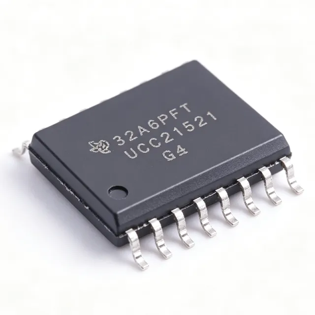
UCC21521DWR - 4A/6A 5.7kVrms Isolated Gate Driver | TI
The Texas Instruments UCC21521DWR is a 4-A source / 6-A sink dual-channel reinforced isolated gate driver with 5.7-kV RMS galvanic isolation, at least 100 V/ns common-mode transient immunity (CMTI), and a 16-pin SOIC (DW) package. An isolated gate driver is a power-management IC that translates low-voltage control logic from a microcontroller or DSP into the high peak current required to switch power transistors, while maintaining galvanic isolation between the control side and the power stage. Within the power-electronics hierarchy it sits between PWM controllers and MOSFETs, IGBTs, or SiC MOSFETs, and it is essential for safety isolation and noise immunity in high-voltage converters. Key features include 19-ns typical propagation delay, 5-ns maximum channel-to-channel matching, 6-ns maximum pulse-width distortion, and a 10-ns minimum input pulse width. These tight timing specifications reduce switching losses and minimize shoot-through risk. The DIS enable pin supports power sequencing and fast fault shutdown, and programmable dead time (for half-bridge configurations) prevents cross-conduction. Technically, the UCC21521 uses TI capacitive isolation technology to deliver the 5.7-kV RMS reinforced barrier with CMTI of at least 100 V/ns, making it robust in high dv/dt SiC environments. Input thresholds are TTL and CMOS compatible for direct 3.3-V logic interfacing, and an 8-V UVLO protects the power switch from under-driven operation. Typical applications include motor drives, solar string inverters, EV onboard chargers, and isolated DC-DC converters, where the 4-A/6-A drive strength and up-to-5-MHz switching capability suit SiC and IGBT power stages. Design tip: place decoupling capacitors directly at VCCI and VDDA/VDDB pins and minimize gate-loop inductance to achieve the datasheet timing figures and avoid dv/dt-induced false triggering. This page adds value beyond the datasheet with drop-in alternative comparisons, pricing tiers, and practical layout notes synthesized from distributor and manufacturer data.
UCC21521Q-Q1 - 4A/6A 5.7kVRMS Dual Gate Driver | Texas Instruments
The Texas Instruments UCC21521Q-Q1 is an AEC-Q100 qualified, 5.7-kVRMS isolated dual-channel gate driver delivering 4-A source and 6-A sink peak output current, housed in a 16-pin SOIC (DW) package. The device is universal in topology, supporting dual low-side, dual high-side, or half-bridge driver configurations, and includes an enable pin for system-level control. An isolated gate driver is a power management IC that provides galvanic isolation between the low-voltage controller side and the high-voltage power stage, allowing a microcontroller to safely drive power semiconductor switches such as MOSFETs, SiC FETs, and IGBTs. Gate drivers form the interface layer of the power-conversion hierarchy: controller -> signal isolator -> gate driver -> power switch. Key features include capacitive-coupled isolation rated at 5700 Vrms, high CMTI (common-mode transient immunity) for fast-switching wide-bandgap applications, a UVLO (undervoltage lockout) on both input and output supplies that prevents erratic gate drive during power-up, and an enable pin that places both outputs low for safety interlocks. The 4-A/6-A asymmetrical drive strength provides strong turn-off capability that minimizes switching losses and improves dv/dt immunity against parasitic turn-on. The Q1 grade guarantees operation from -40C to +125C ambient under AEC-Q100 automotive qualification, making the device suited to traction inverters, on-board chargers, and 48V systems. The universal channel configuration lets a single bill-of-material position cover half-bridge, dual low-side, and dual high-side designs, reducing qualification overhead across platforms. Typical applications include automotive traction inverters, OBC PFC and LLC power stages, DC fast-charger modules, solar string inverters, and industrial motor drives driving SiC or IGBT switches. The wide-body creepage and clearance of the SOIC-16 (DW) package supports reinforced isolation designs. Design consideration: size the gate-loop resistance to balance switching speed against ringing, and place the driver close to the power switch to minimize loop inductance; always verify CMTI margin against the fastest dv/dt in the system. Pricing data as of 2026-08-29; see tiers below for quantity pricing.

UCC21530 - 4A/6A 5.7kVRMS Isolated Dual Gate Driver | TI
The Texas Instruments UCC21530 is an isolated dual-channel gate driver delivering 4A source and 6A sink peak output current in a 14-pin SOIC (DWK) package. It is designed to drive IGBTs, Si MOSFETs, and SiC MOSFETs at switching frequencies up to 5MHz, with a 5.7kVRMS reinforced isolation barrier and a minimum common-mode transient immunity (CMTI) of 125V/ns. An isolated gate driver is a specialized power-management IC that provides galvanic isolation between a low-voltage controller (MCU or PWM controller) and a high-voltage power stage while supplying the peak current required to switch power transistors rapidly. It sits in the power electronics signal chain between the digital controller and the gate of an IGBT or MOSFET. The UCC21530 uses a capacitive isolation architecture, which enables high-speed signal transfer with low power consumption compared with optocoupler-based drivers. Key features include 4A/6A peak output current, 5.7kVRMS reinforced isolation, 125V/ns minimum CMTI, 3.3mm channel-to-channel spacing, an enable pin, and programmable dead time via the DT pin. According to the TI datasheet, the device offers best-in-class propagation delay and low pulse-width distortion, which reduces dead-time losses and enables precise, efficient switching. Undervoltage lockout (UVLO) on both the input and output sides adds system-level robustness. Architecturally, the UCC21530 comprises an input-side controller coupled through a capacitive isolation barrier to two secondary-side drivers. The reinforced barrier supports demanding safety standards, while internal functional isolation between the two outputs allows independent high-side and low-side operation in half-bridge and full-bridge configurations without external isolation components. Typical applications include three-phase motor drives, solar string inverters, EV onboard chargers, UPS systems, and server power supplies. High peak current and low propagation delay minimize switching losses, while high CMTI prevents false gate triggering at rapidly slewing switch nodes in SiC designs. When designing with the UCC21530, minimize gate-loop parasitic inductance, set dead time correctly via the DT pin to prevent shoot-through, and verify UVLO thresholds against your rail-sequencing plan for reliable startup. Pricing as of 2026-08-30 is available from authorized distributors listed in data sources.

UCC21530DWKR - 4A/6A Dual-Channel Isolated Gate Driver | TI
The Texas Instruments UCC21530DWKR is a 4A source / 6A sink, 5.7 kVRMS reinforced-isolated dual-channel gate driver in a 14-pin SOIC (DWK) package with 3.3 mm channel-to-channel spacing. It is engineered to drive IGBTs, silicon MOSFETs, and SiC MOSFETs up to 5 MHz switching frequency, with a minimum 125 V/ns common-mode transient immunity (CMTI) rating. A galvanically isolated gate driver is a power-semiconductor interface IC that translates low-voltage PWM control signals from a digital controller (MCU, DSP, or FPGA) into the high-voltage, high-current drive required to switch the gate of a power transistor. It belongs to the broader hierarchy of gate driver -> power management IC -> signal conditioning -> power conversion. Reinforced isolation, defined by IEC 60747-17, provides a 5.7 kVRMS working voltage plus transient overvoltage protection between the low-voltage primary side and the high-voltage secondary side, eliminating the need for optocouplers or external bootstrap circuits in many topologies. Key features include 4 A peak source / 6 A peak sink drive capability, 5.7 kVRMS reinforced isolation per UL 1577, 8 V to 18 V VDD supply range (VDDA/VDDB up to 25 V), programmable dead-time control via the DT pin, an enable pin for simultaneous shutdown of both outputs, internal functional isolation between the two secondary sides, and an extended -40C to +125C operating temperature range. The wide drive-voltage capability supports SiC MOSFET turn-on enhancement and IGBT gate-charge requirements across many power classes. The device employs TI's capacitive isolation technology using an internal SiO2 dielectric barrier, achieving CMTI of at least 125 V/ns and supporting switching frequencies up to 5 MHz. Fail-safe logic ensures that primary-side faults force both outputs LOW, preventing catastrophic half-bridge shoot-through conditions in motor drive and inverter applications. Typical applications include solar inverters, industrial motor drives (AC induction, BLDC, PMSM), telecom DC/DC converters using DAB/PSFB topologies, EV charging stations (OBC and DC fast charge), SiC FET-based high-frequency converters, and Class D audio amplifiers. The reinforced isolation barrier also allows direct drive of 600 V / 1200 V / 1700 V class power stages without additional isolation. When designing with the UCC21530DWKR, choose decoupling capacitors of at least 1 uF low-ESR ceramic on each VDD rail placed within 5 mm of the IC pins. The DT pin resistor sets dead time and must be selected based on the specific power-switch turn-off delay to prevent cross-conduction; consult the datasheet's dead-time programming section for the recommended resistor range. This page synthesizes distributor pricing, parametric drop-in alternatives, and practical PCB layout notes not consolidated on the manufacturer datasheet front page, providing engineers with a single decision-ready reference.

UCC21530Q-Q1 - 4A/6A 5.7kVRMS Isolated Gate Driver | TI
The Texas Instruments UCC21530Q-Q1 is an AEC-Q100 qualified, reinforced isolated dual-channel gate driver delivering 4A source and 6A sink peak output current, designed to drive IGBTs, Si MOSFETs, and SiC MOSFETs at switching frequencies up to 5MHz. It comes in a 14-pin SOIC (DWK) package with a 5.7kVRMS reinforced isolation barrier providing 3.3mm channel-to-channel spacing. An isolated gate driver is a power management IC that transfers logic-level PWM control signals across a galvanic isolation barrier to drive the gate of a high-side or low-side power switch floating at high voltage. Within the power-electronics hierarchy (gate driver -> isolated driver IC -> power management IC -> semiconductor), the UCC21530-Q1 occupies the critical interface between a microcontroller such as the TMS320F28004x C2000 family and the power stage. Key features include best-in-class propagation delay and pulse-width distortion, programmable dead time via a single DT pin resistor, a common-mode transient immunity (CMTI) of at least 125V/ns for operation on fast-switching GaN and SiC bridges, and TTL/CMOS-compatible input thresholds independent of the VDDI supply. An enable pin allows global shutdown, and both outputs can be interlocked for half-bridge configurations. The capacitive isolation architecture supports a maximum repetitive peak isolation voltage suitable for 800V-class automotive systems such as on-board chargers and traction inverters, though designers should verify creepage requirements against the 3mm package spacing. Wide VDDI operation on the output side accommodates 5V-to-20V gate-drive rails needed for SiC MOSFETs. Typical applications include automotive traction inverters, 800V on-board chargers (OBC), DC-DC converters, motor drives, and solar inverters. Pairing the driver with SiC MOSFETs such as the LMG3422 GaFET ecosystem or discrete SiC switches yields low-loss, high-frequency power stages. Design tip: size the DT-pin resistor precisely to set dead time, and place a low-ESR decoupling network (1uF plus 100nF) directly at VDDA and VDDB to sustain 4A/6A peak gate currents without droop.
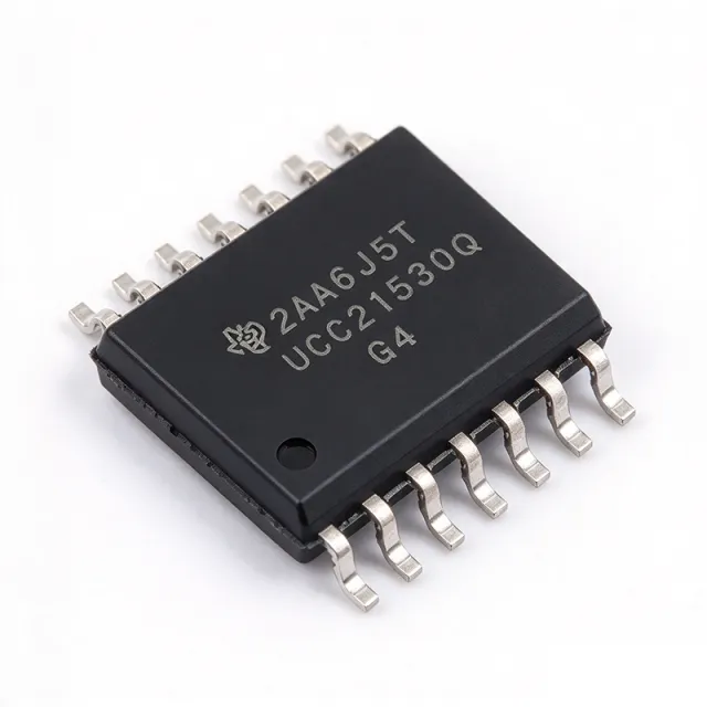
UCC21530QDWKRQ1 - 4A/6A 5.7kVrms Isolated Gate Driver | TI
The Texas Instruments UCC21530QDWKRQ1 is an automotive-grade, 4-A source / 6-A sink, 5.7-kVRMS reinforced isolated dual-channel gate driver with enable and programmable deadtime, housed in a 14-pin DWK (SOIC-14 wide-body) package. It drives IGBTs, SiC MOSFETs, and GaN power switches up to 5 MHz with best-in-class propagation delay (33 ns typical) and pulse-width distortion. The reinforced isolation barrier is rated to 5.7 kVRMS with a minimum 8.5-mm creepage / clearance and 3.3-mm channel-to-channel spacing, simplifying UL 1577 and IEC 60747-17 compliance for high-voltage systems. An isolated gate driver is a switching power-supply sub-system that translates low-side logic-level PWM into a high-voltage, floating gate-drive signal referenced to the switched-node of a half-bridge. It belongs to the gate-driver IC family, a category within power MOSFET/IGBT drivers, under the broader power management hierarchy. The UCC21530-Q1 integrates a silicon-oxide isolation transformer, two output channels (the chip itself), and is AEC-Q100-qualified for automotive environments by design. Key features include 4-A peak source and 6-A peak sink output current, a wide 18-V to 25-V VDD/VDDA range (3-V to 18-V on logic side), 33-ns typical propagation delay, 5-ns maximum channel-to-channel delay matching, 100-V/ns CMTI, and integrated programmable deadtime (DT) for shoot-through prevention. An active-low enable pin and a fault-ready open-drain output support sequencing and desaturation monitoring in three-phase inverters and PFC stages. Typical applications include traction inverters for EV powertrains, on-board chargers (OBC), industrial servo drives, solar string inverters, telecom DC/DC converters, and any 400-V / 800-V bus half-bridge topology requiring reinforced isolation. The DWK wide-body SOIC package provides 8.5 mm of creepage for high-voltage pollution-degree-2 environments. When designing with the UCC21530-Q1, place 1-uF / 100-nF decoupling on VDD/VDDA/VCCI close to the IC pins. Use a bootstrap diode + capacitor on the high-side channel whose voltage rating is rated for the DC bus plus transient ringing. Always respect the absolute-maximum VDD/VDDA of 30 V to avoid catastrophic gate-oxide damage. This page synthesizes distributor pricing, drop-in alternatives, and practical design notes not consolidated in the manufacturer datasheet — including same-package TI options, cross-brand validation notes, and BOM-optimization guidance unavailable on DigiKey/Mouser product pages.
UCC21540 - 4A/6A 5.7kVRMS Isolated Gate Driver | Texas Instruments
The Texas Instruments UCC21540 is a reinforced isolated dual-channel gate driver delivering up to 4-A peak source and 6-A peak sink current to drive power MOSFETs, IGBTs, and GaN transistors. It carries a 5.7-kVRMS galvanic isolation rating, and the DWK package option provides 3.3-mm channel-to-channel spacing for high bus-voltage industrial designs. An isolated gate driver is a specialized IC that provides galvanic isolation between a low-voltage controller and a high-voltage power stage, enabling safe, ground-loop-free switching of power transistors in the power-conversion hierarchy: gate driver -> isolated driver -> power management IC. The UCC21540 belongs to the UCC2154x family within TI's broad isolated gate driver portfolio, optimized for 10-12V driven MOSFETs and IGBTs. Key features include 4-A/6-A peak drive strength, 5.7-kVRMS reinforced isolation per the capacitive isolation technology, a programmable-deadtime (DT) pin that prevents shoot-through in half-bridge configurations, a disable (DIS) pin for system-level fault shutdown, and an 8-V UVLO on the secondary-side supply. VDD on the output side operates from 6.5V to 18V, supporting both dual low-side and half-bridge topologies. Technically, the device uses TI capacitive isolation technology, delivering fast propagation delay, low channel-to-channel matching error, and high common-mode transient immunity (CMTI), which is essential when switching at high frequency across large dv/dt events such as GaN half-bridge transitions. The dual-input configuration accepts both PWM-style inverting/non-inverting inputs for flexible control interfacing. Typical applications include server and telecom power supplies, industrial motor drives, solar string inverters, and EV onboard chargers, where its combination of drive strength, deadtime control, and isolation robustness maximizes converter efficiency and reliability. Design tip: keep the gate-drive loop compact, set the DT pin resistor for the deadtime your switches require, and respect creepage/clearance spacing on the PCB. According to TI, pricing and availability as of 2026-08-30.