开发板
产品(182)

NTS0304EUK-ARD - NTS0304E Level Translator Eval Board | NXP
The NXP Semiconductors NTS0304EUK-ARD is an Arduino-compatible evaluation daughterboard for the NTS0304E, a 4-bit dual-supply translating transceiver with open-drain outputs and auto-direction sensing, enabling rapid test and design-in of bidirectional voltage level translation. An evaluation board (also called a development or demonstration board) is a printed circuit assembly that mounts a target device, in this case the NTS0304E level translator IC, together with supporting circuitry, connectors, and test points so engineers can characterize the device without designing a custom PCB. Evaluation boards sit within the broader hierarchy of development tools, which also include motherboards, starter kits, and software stacks, and they are typically the first step between reading a datasheet and committing a component to production hardware. The NTS0304EUK-ARD equips an Arduino port for direct stacking onto Arduino-compatible motherboards, and it is documented as fully compatible with several NXP evaluation kits (EVKs). Per the NTS0304E datasheet, the underlying IC provides eight 1-bit input-output ports (A-side and B-side), one output-enable input (OE), and two supply pins. VCC(A) can be supplied at any voltage between 0.95 V and 3.6 V, and VCC(B) supports a separate, independently chosen supply domain, allowing translation across multiple voltage domains. A key strength of this platform is its on-board test circuitry. According to the NXP user manual UM11762, the daughterboard contains a digital potentiometer accessible via both SPI and I2C interfaces, letting users exercise and measure the static and dynamic characteristics of the device under test (DUT). A loopback circuit is also included so the bidirectional, auto-direction-sensing capability of the NTS0304E can be verified without external instrumentation beyond a host microcontroller. Typical use cases include validating level shifting between 1.8 V, 2.5 V, and 3.3 V logic domains in embedded systems, prototyping I2C and SPI bus translation for sensors and memory devices, and demonstrating open-drain bidirectional signaling in mixed-voltage industrial and consumer designs. When evaluating, remember that the open-drain architecture requires appropriate pull-up resistors on both A-side and B-side ports; sizing these resistors against bus capacitance sets the achievable rise time and maximum data rate. This page consolidates distributor pricing, the official NXP user manual reference, application guidance, and sourcing information for the NTS0304EUK-ARD that is not available on a single manufacturer or distributor page.
NVIDIA RTX A5000 - 24GB GDDR6 Workstation GPU | NVIDIA
The NVIDIA RTX A5000 is a professional workstation graphics card built on the NVIDIA Ampere architecture, combining 8,192 CUDA cores, 256 third-generation Tensor Cores, 64 second-generation RT Cores, and 24 GB of GDDR6 graphics memory on a 384-bit interface with 768 GB/s memory bandwidth. A workstation GPU is a specialized graphics processing unit designed for professional workloads such as 3D rendering, AI training and inference, scientific simulation, and broadcast production. Within NVIDIA's product hierarchy, the RTX A5000 sits in the mid-to-upper Ampere workstation family between the RTX A4000 and the RTX A6000, delivering certified drivers and ISV application support that consumer GeForce cards do not provide. Key features include 24 GB of ECC-enabled GDDR6 memory, which protects long-running renders and AI datasets from silent memory errors; single-precision performance of 27.8 TFLOPS; third-generation NVLink support for scaling two RTX A5000 cards into a single 48 GB multi-GPU pool; and PCI Express Gen 4.0 host bandwidth. AV1 decode support makes it suitable for modern video streaming and broadcast pipelines. The Ampere architecture pairs RT Cores for hardware-accelerated ray tracing with Tensor Cores for DLSS and AI acceleration, allowing photorealistic rendering and neural workloads to run on the same board. The GA102-class silicon is optimized for sustained professional duty cycles with workstation-grade reliability targets. Typical applications include AI model development and inference, real-time ray-traced rendering in DCC tools such as Autodesk Maya and Blender, medical imaging, and broadcast video production. Design consideration: verify workstation power envelope and airflow; professional cards are tuned for continuous 24/7 load rather than bursty gaming duty. This page synthesizes datasheet specifications, same-family drop-in alternatives, application guidance, and FAQs not consolidated in the NVIDIA datasheet.
NVT4558-4858-EVB - SD/SIM Level Shifter Eval Board | NXP
The NXP Semiconductors NVT4558-4858-EVB is an evaluation board for the NVT4558 and NVT4858 SD/SIM level translator interface ICs, featuring mounted NVT4558/NVT4858 devices, onboard input and output headers, and SD and SIM card sockets for effortless evaluation of SD and SIM card interface level shifting. An SD/SIM level shifter evaluation board is a hardware development tool in the broader hierarchy of development boards, kits, and programmers. Its purpose is to let engineers exercise a level-translator IC in a realistic card-interface environment - card sockets, controller headers, and controlled supply rails - before committing the IC to a custom PCB. Evaluation boards of this class sit under the development board category and serve the interface IC validation stage of embedded system design. Key features include the factory-mounted NVT4558 and NVT4858 level translators, onboard input and output headers for direct signal access, and a combined SD and SIM card socket. According to NXP documentation, the NVT4558 is compliant with all ETSI, IMT-2000 and ISO-7816 SIM/smart card interface requirements, so the board reproduces the electrical conditions these standards demand. A distinctive capability of this board is its dual operating mode. It can be used stand-alone using the onboard headers and SD/SIM sockets, or connected to an SD/SIM controller via a 14-pin or 20-pin ribbon cable. Ribbon cable connection allows the SD/SIM controller to access the SD/SIM card inserted in the onboard socket, enabling end-to-end host-controller testing without any custom hardware. Typical applications include evaluating SD card and SIM card level shifting in mobile, POS terminal, set-top box, and embedded controller designs where a host controller operating at one voltage domain must interface with cards at another, and where standards such as ISO-7816 and ETSI requirements must be met. For design-in work, consult the NXP user manual UM11855, which is intended to help users quickly set up, configure and operate the NVT4558-4858-EVB evaluation board in the user's hardware platform. This page synthesizes distributor pricing sources, board architecture details, and practical evaluation guidance not found on a single manufacturer or distributor page.
NVT4858-4557-EVB - SD/SIM Level Shifter Eval Board | NXP
The NXP NVT4858-4557-EVB is an easy-to-use level shifter interface evaluation board carrying a mounted NVT4858 SD/SDIO voltage translator and an NVT4557 SIM/smart-card level translator, with on-board input and output headers, one SD card socket, and one SIM card socket for effortless evaluation of both devices. According to NXP, the board lets users evaluate SD or SIM level shifting through simple header connections to any host MCU platform. A voltage level translator is an interface IC that safely bridges digital signals between circuits operating at different supply voltages - for example a 1.8 V microcontroller SDIO port and a 3.3 V SD card. Within the signal-chain hierarchy, level translators sit in the interface IC family alongside buffers and repeaters, and are essential wherever mixed-voltage memory cards or smart cards interface to lower-voltage SoCs. Key features of the evaluation platform include: the NVT4858 supporting SD 3.0 SDR104, SDR50, DDR50, SDR25 and SDR12 modes plus SD 2.0 High-Speed (50 MHz) and Default-Speed (25 MHz) modes; the NVT4557 being compliant with all ETSI, IMT-2000 and ISO-7816 SIM/smart-card interface requirements; and the NVT4858 device itself providing an integrated EMI filter and ESD protection. These integrated protection features reduce external component count in the final product design. Technically, the NVT4858 is a dual-voltage level translator dedicated to SD, SDIO, mini SD, micro SD and SIM card interfaces. Its integrated EMI filtering suppresses radiated emissions on the high-speed card clock and data lines, while the ESD protection structure guards the card-side pins against electrostatic discharge events during card insertion - a common field-failure source. The companion NVT4557 handles the ISO-7816 smart-card signaling chain. Typical evaluation use cases include prototyping SD/SDIO host controllers in embedded Linux or MCU designs, validating SIM card interfaces for LTE, IoT and POS terminals, and benchmarking signal integrity on the card clock/data lines before committing to a PCB layout. A key design consideration: NXP notes that NVT4858 is not a drop-in replacement for the older NVT4857 - both hardware and software modifications may be required when migrating, so engineers should review the NVT4858 datasheet and application note AN13158 for layout guidelines. This page synthesizes distributor availability, the official NXP user manual (UM11582), application note references, and practical design notes not found on the manufacturer product page alone.
OM-O2P-EVAL - Omega2+ IoT Eval Board | Onion | Wi-Fi 4
The Onion OM-O2P-EVAL is an evaluation and development board for the Onion Omega2+ IoT computer module, integrating a 2.4 GHz 802.11 b/g/n (Wi-Fi 4) transceiver and exposing the Omega2+ module through a breadboard-friendly form factor. Per the Onion product family datasheet, the kit ships with the Omega2+ SoM pre-soldered onto the carrier, giving developers immediate access to a Linux-based, Wi-Fi-enabled computing platform for prototyping connected hardware. The board targets makers, IoT engineers, and educators who need to evaluate the Omega2+ module without designing a custom carrier. An evaluation board (eval board or development kit) is a reference PCB produced by a module vendor that breaks out every signal of a system-on-module (SoM) into accessible headers and adds power regulation, USB, and user I/O so engineers can verify functionality with minimum hardware effort. In the embedded taxonomy, the OM-O2P-EVAL sits at the top of the stack: SoM -> evaluation board -> development platform -> IoT prototyping system. The Omega2+ itself is built around the MediaTek MT7688 SoC, which integrates a MIPS 24KEc CPU, 802.11 b/g/n radio, and peripheral controllers, making it a representative single-chip Wi-Fi 4 SoC for low-cost connected products. Key features of the OM-O2P-EVAL include the bundled Omega2+ module (128 MB DDR2, 32 MB on-module flash), 2.4 GHz 802.11 b/g/n Wi-Fi 4 radio, USB 2.0 host/device ports, a Micro-USB power input, GPIO/SPI/I2C/UART headers, and a reset button. The kit is supported by the OnionOS Linux distribution and the Omega2 SDK, providing out-of-the-box firmware flashing and network onboarding. Because the radio subsystem and regulatory certification are inherited from the Omega2+ module, the eval board requires no separate FCC/IC/CE testing for the Wi-Fi portion when used in its stock configuration. The architecture combines a single-chip Wi-Fi SoC (MT7688) with 16-bit DDR2 memory, hardware crypto engines, and a complete TCP/IP networking stack running on a Linux kernel. Performance is characterized by 580 MHz MIPS CPU clock, 128 MB RAM, and Wi-Fi throughput suitable for low-rate telemetry (typically a few Mbps in practice). Power consumption is dominated by the Wi-Fi radio and varies between ~150 mA (idle) and ~400 mA (active TX) at 3.3 V. Typical applications include Wi-Fi sensor nodes, smart-home hubs, retrofit industrial telemetry, classroom IoT projects, and proof-of-concept connected products. The wide software support (Node.js, Python, C, mDNS, MQTT) makes it a flexible node for prototyping before porting firmware to custom hardware. Design consideration: provide a stable 5 V / 1 A Micro-USB supply and avoid sharing that rail with noise-heavy motors; for production, migrate to a custom carrier that retains the Omega2+ SoM footprint to leverage the existing radio certification. This page synthesizes distributor inventory, drop-in alternatives, and engineering notes not found in a single manufacturer datasheet.
ONET1131EC-EVM 11.7-Gbps EML Driver EVM | TI
The Texas Instruments ONET1131EC-EVM is an evaluation module for the ONET1131EC, a 2.5-V electro-absorption modulated laser driver operating from 9.8 Gbps to 11.7 Gbps without a reference clock. The associated ONET1131EC combines a modulator driver, transmit clock and data recovery, and an integrated limiting amplifier in a VQFN package. The EVM is a development board rather than the production IC itself. An EML driver is a high-speed semiconductor interface device that converts an electrical data stream into the drive required by an external electro-absorption modulated laser. The ONET1131EC family sits within high-speed optical transceiver signal-chain electronics, where transmit data must remain stable across long data rates and optical-module environments. Clock and data recovery helps the transmitter recover timing from the incoming data, while bypass mode supports operation at lower rates according to the manufacturer information. The key documented operating span is 9.8 Gbps to 11.7 Gbps, and the device is identified as a 2.5-V EML modulator driver. Its integrated limiting amplifier and CDR reduce the external signal-chain components required in an optical transmitter prototype. The EVM provides a practical platform for evaluating the ONET1131EC, connecting it to test equipment, and characterizing the transmit path before a production board is designed. ONET1131EC evaluation is suited to optical networking prototypes, 10G-class EML transmitter development, high-speed serial-interface experiments, and transceiver bring-up. The EVM should be treated as a development platform: final production designs still require appropriate power, thermal, impedance-control, signal-integrity, and layout engineering. Before operation, consult the ONET1131EC EVM User's Guide for board connections, test conditions, and supported measurements. The available web sources identify the board and device, but do not provide enough verified detail for every package pin, electrical limit, connector, or compliance attribute; those values are intentionally left unspecified rather than guessed. This page separates the known ONET1131EC-EVM identity and verified operating context from engineering information that still requires the manufacturer documentation.
P3A1604UK-ARD - Arduino Eval Board for 4-bit Level Translator | NXP
The NXP P3A1604UK-ARD is an Arduino-compatible evaluation board for the P3A1604UK, a 4-bit dual-supply translating transceiver with auto direction sensing that enables bidirectional voltage level translation between VCCA (0.72 V to 1.98 V) and VCCB (1.62 V to 3.63 V). The board exposes connections to I2C, I3C, or SPI controllers or targets for rapid prototyping of level-translation circuits. A dual-supply translating transceiver is an interface IC that allows digital signals referenced to one supply domain (for example a 1.2 V core rail) to communicate with devices in a second domain (for example a 3.3 V I/O rail). Within the signal-chain hierarchy, it belongs to the logic translator family under interface ICs, sitting between level shifters, bus switches, and buffers. The P3A1604UK's auto direction sensing removes the need for a direction-control pin, which simplifies firmware and avoids bus contention in bidirectional links. Key features of the underlying device include four 1-bit input-output ports (A and B ports), an output enable input (OE), wide supply ranges of VCCA from 0.72 V to 1.98 V and VCCB from 1.62 V to 3.63 V, and support for emerging standards such as I3C alongside legacy I2C and SPI buses. The evaluation board maps these signals onto standard Arduino headers so that any Arduino-form-factor microcontroller board can drive the translator during bench evaluation. Typical applications validated on this board include interfacing 1.2 V or 1.8 V microcontroller I/O banks to 3.3 V peripherals, translating I3C sensor buses in mobile and IoT designs, and level-shifting SPI flash or display interfaces. Engineers can use the board to verify timing, drive strength, and power sequencing before committing to a custom PCB footprint. A key design consideration: because the translator is a dual-supply device, the evaluation setup should confirm correct VCCA/VCCB power-up order behavior and OE control with the target controller before tape-out. According to NXP product documentation, the P3A1604UK datasheet (24 pages, 449 kB PDF) covers the full electrical and switching characteristics needed for production design. This page synthesizes distributor availability data, datasheet-derived specifications, and practical design notes not found on the manufacturer product page alone, providing a single citable reference for the P3A1604UK-ARD evaluation platform.
P3A9606JK-EVB - I3C/I2C/SPI Level Translator EV Board | NXP
The NXP P3A9606JK-EVB is an industrial-grade evaluation board for the NXP P3A9606JK dual bidirectional I3C/I2C-bus and SPI voltage-level translator, supporting voltage translation between 0.72 V and 1.98 V with connections to I2C, I3C, or SPI controllers or targets. A level translator (also called a level shifter or voltage translator) is an interface IC or board that safely connects digital devices operating at different supply voltages, such as a 1.8 V microcontroller communicating with a 3.3 V sensor. Within the signal-integrity hierarchy, level translators sit in the broader interface and logic family of voltage-translation devices, which also includes buffers, repeaters, and bus switches. The P3A9606JK belongs to the auto-direction-sensing translating transceiver class, meaning no direction-control pin is required in I2C/SMBus open-drain use. Key features of the underlying P3A9606JK include 2-bit (2-channel) bidirectional translation, dual-supply operation covering 0.72 V to 1.98 V rails, automatic direction sensing, native support for traditional open-drain I2C-bus and SMBus traffic, 12.5 MHz I3C-bus operation with combined open-drain and push-pull signaling, and push-pull SPI translation when two devices are paired. Fall-accelerator circuitry accelerates falling edges in open-drain mode, preserving rise/fall timing budgets on heavily loaded buses. Architecturally, the P3A9606JK is a dual-supply translating transceiver: each channel uses a pass-gate with edge accelerators rather than a simple MOSFET open-drain divider, which is what enables 12.5 MHz I3C push-pull phases and SPI rates that conventional BSS138-style discrete shifters cannot sustain. Typical applications include I3C sensor buses in automotive and industrial systems, SPMI and I2C level translation between low-voltage PMICs and controllers, and SPI rail conversion between SoCs and peripherals. The EVB lets engineers evaluate all these modes before committing to the SOT2015-1 packaged IC in production layouts. Design consideration: use the EVB with short jumper wires and proper grounding; the user manual UM11385 documents board setup, jumper configuration, and connection to the user hardware platform. This page synthesizes distributor availability, evaluation-board documentation, and practical usage guidance not found in a single manufacturer source.
PCA9421UK-EVM - PCA9421 PMIC Evaluation Board | NXP
The NXP Semiconductors PCA9421UK-EVM is an evaluation board for the PCA9421, a highly integrated Power Management IC (PMIC) targeted at low-power microcontroller applications powered by Li-ion batteries. The board exposes all PCA9421 power rails and control interfaces, allowing engineers to measure efficiency, sequencing behavior, and load-transient response before committing to a production PCB design. A PMIC (Power Management IC) is a class of power management semiconductor that integrates multiple voltage regulators, load switches, and control logic into a single device. In the power-management hierarchy, a PMIC sits above individual LDOs and buck converters, combining them with I2C-configurable sequencing to serve an entire low-power system from one battery input. The PCA9420/PCA9421 family is specifically aimed at battery-powered microcontroller systems. Key features of the evaluation platform include direct access to the PCA9421 regulator outputs, configuration of the device through its serial control interface, and test points for measuring regulator performance. According to NXP, the board is designed to help users evaluate the features and performance of both the PCA9420 and PCA9421 devices, since the two PMICs share the same evaluation platform and differ mainly in their configuration options. Technical depth: the PCA9421 integrates multiple regulated outputs intended to power MCU cores, peripherals, and RF or sensor rails from a single-cell Li-ion source. The EVM routes these outputs to headers and measurement points so that ripple, startup sequencing, and quiescent current can be characterized with standard bench instrumentation. NXP user manual UM11987 documents the Getting Started tab, downloadable assets, and quick-reference setup information for the board. Typical applications include low-power microcontroller systems, battery-powered IoT sensor nodes, portable devices running from a Li-ion cell, and any design evaluating the PCA9420/PCA9421 PMIC family for production use. Design consideration: the board is intended for engineering development or evaluation purposes only, per the NXP user manual; it is not a reference design for direct production copy, so production layouts should follow the PCA9421 datasheet layout guidelines. This page synthesizes distributor availability data, the NXP product page, and the evaluation board user manual, plus practical evaluation guidance not found in the datasheet alone.
PCA9422-EVB - PCA9422 PMIC Evaluation Board | NXP
The NXP PCA9422-EVB is an evaluation board for the PCA9422 Power Management IC (PMIC), supporting the Arduino UNO interface with an onboard ADC for GUI-based monitoring of all regulator voltages. An evaluation board is a pre-assembled circuit platform that lets engineers exercise every function of an integrated circuit before committing to a custom PCB design. Within the product hierarchy, evaluation boards sit in the development tools category, above bare ICs (here, the PCA9422 PMIC -> power management IC -> semiconductor), and typically include all supporting circuitry: regulators, connectors, configuration jumpers, and software hooks. The PCA9422-EVB exemplifies this category by exposing the full PCA9422 feature set through standard interfaces and a graphical user interface. Key features include the Arduino UNO compatible expansion interface, an onboard analog-to-digital converter that streams all regulator voltages to a PC GUI, and pre-populated external components matching the recommended PCA9422 application circuit. The board allows rapid configuration of the PMIC regulators and modes without soldering. The underlying PCA9422 is a highly-integrated PMIC targeted at full power management solutions for low-power microcontroller applications or applications with small batteries, as described by NXP documentation. It provides multiple regulators in a single device, reducing board area and BOM count in battery-powered designs. Typical use cases include early-stage evaluation of the PCA9422 for low-power MCU power supplies, validation of regulator sequencing and modes, prototyping of small-battery power architectures for i.MX RT-class or general microcontroller systems, and training or demonstration platforms. A key design consideration is that the EVB reflects the NXP reference layout; results obtained on this board, including regulator thermal behavior and EMI, may differ from a custom layout, so final validation on production hardware is still required. This page synthesizes distributor availability, board-level design notes, and practical evaluation guidance not found in the manufacturer datasheet alone.
PCA9451A-EVK - PMIC Eval Kit for i.MX 93x | NXP Semiconductors
The NXP Semiconductors PCA9451A-EVK is an evaluation kit for the PCA9451A single-chip power management IC (PMIC) designed to support the i.MX 93x processor family, providing full access to all PMIC features through a 6-buck, 3-LDO power architecture and an included FTDI USB-to-I2C interface cable. A power management IC (PMIC) is an integrated circuit that consolidates multiple voltage regulators, load switches, and supervisory functions into one device, sitting at the top of the power management IC hierarchy alongside voltage regulators and battery management ICs. In battery-powered and adapter-powered embedded systems, a PMIC replaces a multi-chip power tree, reducing board area, bill-of-materials count, and power-sequencing complexity for application processors such as the NXP i.MX 93x family. The PCA9451A-EVK provides out-of-the-box access to the underlying PCA9451A features: six high-efficiency step-down (buck) regulators, three LDOs, one 400 mA load switch, a 2-channel level translator, and a 32.768 kHz crystal oscillator driver. The board supports both 1-cell Li-ion and Li-polymer battery applications and 5 V adapter (non-portable) applications, mirroring the two power scenarios targeted by the PMIC. Technically, the kit ships with an FTDI cable that acts as an I2C-to-USB communication interface, allowing engineers to read and write the PMIC configuration registers from a PC using the companion PCA9451A GUI software. This enables interactive adjustment of regulator output voltages, sequencing order, and protection thresholds without soldering or firmware changes, dramatically shortening power-tree bring-up time on i.MX 93x based designs. Typical applications include evaluating the PCA9451A before board spin for portable i.MX 93x products, prototyping power sequencing for industrial and consumer microcontroller/microprocessor systems, and validating battery-charger and load-switch behavior under real firmware control. A key design consideration: configuration changes made through the GUI reside in PMIC registers; final production designs should implement the validated register map in hardware OTP or host firmware, not rely on the EVK configuration path. This page synthesizes distributor pricing, evaluation-kit alternatives, and practical bring-up design notes not found together in the manufacturer documentation.
PCA9617ADP-ARD - Fm+ I2C-Bus Repeater Eval Board | NXP
The NXP PCA9617ADP-ARD is an Arduino-compatible evaluation expansion board for the PCA9617A, a level-translating Fast-mode Plus (Fm+) I2C-bus repeater IC supporting bus speeds up to 1 MHz, with level shifting between a low-voltage side of 0.8 V to 5.5 V and a higher-voltage side of 2.2 V to 5.5 V, supplied as a ready-to-use daughter card with an Arduino port. An I2C-bus repeater (also called a bus buffer) is an interface IC that regenerates and buffers the SDA and SCL signals, allowing longer buses, more loads, and different supply domains to coexist on the same two-wire bus. Within the interface hierarchy, the repeater sits between an I2C controller (master) and its peripherals, extending the reach of what a plain pull-up-limited bus can achieve, and it is a member of the broader family of signal buffers and level translators in system I/O design. Key features of the PCA9617ADP-ARD stem directly from the onboard PCA9617A: bidirectional buffering for both data (SDA) and clock (SCL), Fast-mode Plus operation at up to 1 MHz, support of SMBus applications, and true level translation without direction pins because the open-drain I2C topology is inherently bidirectional. The Arduino port makes the board a plug-on expansion for NXP i.MX 8M Mini LPDDR4 EVKs via a 2 x 20 interposer, as well as standard Arduino-shield headers. The PCA9617A is fabricated in CMOS technology, and its two supply pins (VDD1 and VDD2) can be set independently, which is how the 0.8 V low side accommodates modern 1.0 V to 1.8 V logic domains. Rise-time accelerator drivers actively drive SDA and SCL edges on the high-voltage side, permitting heavier bus capacitance than passive pull-ups alone. Typical applications include evaluating I2C level shifting between microcontrollers and sensors, extending bus capacitance in industrial control systems, and prototyping Fm+ buses between an Arduino host and 3.3 V or 5 V peripherals. A key design consideration: the repeater must be powered on both domains (VDD1 and VDD2), and bus contention with other repeaters in series requires attention to lock-up conditions described in the PCA9617A datasheet. This page synthesizes distributor pricing, related NXP evaluation boards, and practical design notes not found in the manufacturer documentation.
PCF8525-ARD - RTC Evaluation Board for PCF8525 | NXP
The NXP Semiconductors PCF8525-ARD is an Arduino-form-factor expansion evaluation board for the PCF8525, a nano-powered high-accuracy real-time clock (RTC) IC with I2C-bus interface. The board lets designers prototype timekeeping circuits around the PCF8525, whose HVSON package variant delivers temperature-compensated accuracy of up to plus or minus 30 ppm, roughly 5x better than competing RTC solutions. A real-time clock (RTC) integrated circuit is a timing device that maintains seconds, minutes, hours, day, date, month, and year information even when the main system is powered down, typically from a small backup cell. Within the power-management and timing hierarchy, an RTC sits alongside supervisors and microcontrollers, providing a low-power calendar and alarm engine that wakes the host MCU only when needed. Key features of the underlying PCF8525 include an internal temperature compensation engine, a first for external-crystal RTC ICs, which corrects typical crystal drift using a selectable parabolic coefficient of -0.035 ppm/C2 or -0.04 ppm/C2. This software compensation approach removes the need for an expensive temperature-compensated crystal (TCXO) or RTC module, cutting bill-of-materials cost while retaining plus or minus 30 ppm accuracy over temperature in the HVSON variant. The Arduino-compatible (ARD) header format means the board plugs directly onto NXP FRDM development platforms and standard Arduino UNO footprints, exposing the I2C bus (SDA/SCL), power rails, and RTC interrupt outputs to the host MCU. Nano-powered operation keeps backup current extremely low, extending coin-cell life in end products. Typical applications include evaluation of timekeeping for smart meters, battery-powered data loggers, industrial PLCs, and IoT sensor nodes where calendar and alarm functions must survive main-power loss. When evaluating, note that accuracy depends on the chosen crystal and the compensation coefficient setting programmed over I2C, so validate across the full temperature range of your end application. This page synthesizes distributor availability data, the NXP product page, and the PCF8525 datasheet into a single engineering reference, adding drop-in board alternatives and design guidance not found on the manufacturer site.
QPA9510EVB - 900MHz GSM Power Amplifier Eval Board | Qorvo
The Qorvo QPA9510EVB is a fully assembled evaluation board for the QPA9510, a high-power, high-gain, high-efficiency GaAs power amplifier covering the 880 MHz to 915 MHz GSM band (board tuned for 865 MHz to 928 MHz), delivering up to 34 dB of gain, +32 dBm P1dB output power, and single-supply operation from 2.8 V to 3.6 V. An evaluation board (EVB) is a printed-circuit test platform that mounts an IC together with the supporting passive network, connectors, and bias circuitry needed to exercise the device immediately on a lab bench. In the product hierarchy, the QPA9510EVB sits in the RF development tools category, one level above the bare QPA9510 power amplifier IC, which is a semiconductor device within the broader RF amplifier and wireless semiconductor family. Key features include RF input and output connectors for direct integration with vector network analyzers and spectrum analyzers, an analog on-board power controller providing more than 70 dB of gain-adjustment range, and a power-down function: driving the control pin to a logic Low voltage places the amplifier in standby mode. The underlying QPA9510 is fabricated on Qorvo's advanced GaAs process and housed in a compact 3 mm x 3 mm QFN package, and the evaluation board reproduces the datasheet-recommended matching network, including the bill of materials for bias inductors such as L3 and L4 discussed in Qorvo's PK020 documentation. Technically, the board showcases the amplifier's suitability as the final-stage RF amplifier in GSM hand-held equipment in the 900 MHz band and in other UHF applications. The analog bias flexibility lets engineers trade linearity, efficiency, and output power across bias settings while measuring P1dB, gain flatness, and current consumption directly. Typical applications include GSM 900 MHz handset PA prototyping, UHF radio link development, ISM-band (865-928 MHz) transmitter evaluation, and RF lab education and characterization. A key design consideration: the EVB is tuned for the 865-928 MHz range; operating far outside this band requires re-matching the output network, so verify VSWR and thermal performance when re-tuning. This page synthesizes distributor availability data, Qorvo product documentation, and drop-in board-variant alternatives not consolidated on the manufacturer datasheet alone. Pricing is quote-based as of 2026-10-19.
RK3188-SOM - Quad Core Cortex-A9 SoM, 1GB DDR3 | Olimex
The Olimex RK3188-SOM is a compact System-on-Module integrating the Rockchip RK3188 quad-core ARM Cortex-A9 processor with an Actions Semiconductor AC8846 power management unit and 1 GB of DDR3 memory on board. Operating at up to 1.6 GHz, the module exposes every processor signal through five 40-pin 0.05-inch pitch connectors and adds a UART console header plus an SD-card socket. It is intended for fast embedded evaluation and productization of tablets, set-top boxes, and industrial HMIs based on the RK3188 silicon. What is a System-on-Module (SoM)? A SoM is a small board that integrates the core computing components of an embedded system - processor, RAM, PMIC, and boot media - into a single, tested unit that a baseboard can host through high-density board-to-board connectors. SoMs sit in the embedded hierarchy between bare System-on-Chip (SoC) designs (where the integrator places the SoC and DRAM directly on the application board) and full single-board computers (SBCs). The benefit is design reuse: hardware teams can iterate on the application baseboard without re-validating memory, power, and clock trees. Key features of the RK3188-SOM include the Mali-400 MP4 GPU supporting OpenGL ES 1.1/2.0, hardware 1080p H.264 video decode and encode, USB 2.0 OTG and host, I2C/SPI/UART/I2S peripherals brought out through the connectors, and boot from the on-module SD-card socket. The integrated AC8846 PMIC generates all the processor and DDR rails from a single external supply, simplifying baseboard design. Typical applications include Android-based tablets and digital signage, kiosk displays, industrial HMI panels, and prototype media players. The wide signal availability on the connectors also makes the module attractive for firmware bring-up, OS porting (Linux/Android), and education labs needing a deterministic Cortex-A9 quad-core platform. When designing with the RK3188-SOM, ensure the mating baseboard connectors are rated for the 0.05-inch (1.27 mm) pitch and that baseboard decoupling is sized for the in-rush current of the AC8846 PMIC during cold boot. The legacy RK3188 silicon and Android 4.x-era software stack are now considered end-of-life for new consumer designs; choose the RK3288-SoM or RK3566-based modules for new projects requiring long-term OS support. This page synthesizes distributor pricing across DigiKey and Mouser, parameter-by-parameter comparison against related Rockchip SoMs, and practical baseboard design notes - engineering content not present in the manufacturer user manual.
RK3188-SOM-4GB - Quad A9 Cortex SoM w/ 4GB NAND | Olimex
The Olimex RK3188-SOM-4GB is a System-on-Module (SoM) built around the Rockchip RK3188 quad-core ARM Cortex-A9 processor, paired with an Actions Semiconductor AC8846 power management IC and 4 GB of on-board NAND flash. It exposes all RK3188 signals through five 40-pin 0.05" connectors and provides a UART console header plus an SD-card slot for legacy OS media. The 4 GB variant differs from the base RK3188-SOM in that it includes built-in NAND memory, allowing storage of an operating system without requiring an SD card. An SoM (System-on-Module) is a small, self-contained computing board that integrates a processor, memory, power management, and boot storage on a single PCB, exposing high-speed buses and GPIOs through board-to-board connectors so a carrier board can add application-specific I/O. SoMs occupy the middle tier of the embedded hierarchy between discrete SoCs (single-chip solutions) and full SBCs (single-board computers); they are favored when a custom baseboard is needed while reusing a proven compute platform, accelerating time-to-market. Key features include the Rockchip RK3188 SoC with four ARM Cortex-A9 cores running up to 1.8 GHz, a Mali-400 MP4 GPU, hardware 1080p video decode, and an integrated AC8846 PMU that simplifies power-rail design. The module uses 1 GB of DDR3 RAM and 4 GB of NAND flash for persistent storage, removing the SD-card dependency of the base variant. Board-to-board signaling is provided across five 40-pin 0.05" pitch connectors, enabling access to display, camera, USB, GPIO, and high-speed serial interfaces on a user-designed carrier. The RK3188 architecture combines a Cortex-A9 cluster for application processing with a Mali-400 MP4 for graphics acceleration, supporting Android and Linux distributions optimized for the chipset. The AC8846 companion IC integrates DC-DC converters and an LDO array, allowing the carrier board to supply a single input voltage while the SoM handles all downstream rail generation. This partitioning reduces carrier complexity, BOM cost, and design risk. Typical applications include Android/Linux set-top boxes, digital signage, kiosk controllers, retro gaming and emulation platforms, and prototype development of Rockchip-based consumer electronics. The exposed high-speed buses also make the module attractive for industrial HMI and educational platforms where the carrier defines I/O while the SoM provides compute. The legacy RK3188 platform runs Linux kernel 3.0.x and Android 4.x distributions. When designing with this module, ensure the carrier board respects the 0.05" connector pitch and provides adequate thermal dissipation for sustained 1.8 GHz operation, since the RK3188 TDP is non-trivial under full quad-core load. UART console access must be wired to the carrier for Linux/Android debugging during bring-up. The 4 GB NAND variant eliminates SD-card boot reliance but ships pre-formatted for the RK3188 boot loader, so OEM firmware customization should use the official Rockchip SDK. This page synthesizes distributor pricing, drop-in SoM alternatives from the Olimex RK3188 family, and practical design notes not found in the manufacturer datasheet alone.
RK3188-SOM-EVB - RK3188 Quad-Core Cortex-A9 SOM Eval Board | Olimex
The Olimex RK3188-SOM-EVB is an open-source reference design and evaluation board (EVB) for the RK3188-SOM System-on-Module, engineered by Olimex Ltd. to expose HDMI, 100M-byte Ethernet, USB-OTG, 4x USB HS/FS/LS host ports, an LCD connector, RTC with backup battery, audio jacks, and UEXT modules for prototyping Rockchip RK3188 designs. It uses a Rockchip RK3188 quad-core ARM Cortex-A9 SoC clocked up to 1.6 GHz, paired with an Actions AC8846 power management unit, and 1 GB of DDR3 memory on the companion RK3188-SOM module. A System-on-Module (SOM) is a compact, ready-to-integrate computing block that places the CPU, RAM, PMIC, and boot storage on a single PCB, allowing product engineers to focus their own PCB design on application-specific I/O rather than high-speed memory and power-rail layout. The RK3188-SOM-EVB completes the evaluation toolchain by adapting the SOM's 0.05-inch high-density headers to 0.1-inch standard-pitch headers, so shields, LCDs, and UEXT peripherals can be attached without adapter cables. Key features include HDMI output, 10/100 Mb Ethernet, four USB 2.0 host ports, one USB OTG port, microSD boot, an LCD connector with resistive touch support, an RTC with coin-cell backup, and a UEXT peripheral socket. The board accepts +6V to +16V DC on a barrel jack and consumes 0.10-0.15 A at 10 V input when combined with the RK3188-SOM-4GB module. Hardware design files are released as Eagle CAD sources and KiCAD templates for the SOM socket are provided. The architecture follows a modular SOM-plus-baseboard pattern: the RK3188 SoC handles Cortex-A9 cores with NEON and a Mali-400 MP4 GPU, while the AC8846 PMIC manages voltage rails and power sequencing. Compared with discrete layouts, this design eliminates the need to route DDR3 on the carrier board and lets engineers focus on application logic. Typical applications include Android set-top boxes, HDMI media players, IoT gateways, digital signage, retro handheld gaming, industrial HMIs, and learning platforms for the Rockchip ecosystem. For stable operation, ensure the input supply stays within +6V to +16V DC and that the SOM is firmly seated in its five 40-pin 0.05-inch headers. This page consolidates distributor availability, drop-in accessory boards, and design tips not found in the standalone product brief.
RK3308-CC - Quad-Core A35 1.3GHz AIoT Main Board | Rockchip
The Rockchip RK3308-CC (ROC-RK3308-CC) is an AI+IoT open-source main board built around the Rockchip RK3308 64-bit Quad-Core ARM Cortex-A35 application processor running at up to 1.3 GHz, with an integrated high-performance audio CODEC and hardware Voice Activity Detection (VAD) engine. It pairs a compact 60 mm x 45 mm footprint with 256 MB / 512 MB / 1 GB DDR3 options and 4 GB / 8 GB / 16 GB eMMC storage options for cost-effective smart-audio product development. An AIoT open-source main board (ROC form factor) is a credit-card-sized single-board computer built around an integrated application processor, designed to host AI/ML inference, microphone-array audio front-end, and IoT connectivity simultaneously - it is essentially the compute platform that turns a smart-speaker, voice-controlled appliance, or industrial gateway concept into a working prototype without requiring a custom baseboard. In the broader taxonomy it sits between a microcontroller development board and a Linux SBC, sharing the open-source Linux ecosystem of the latter while targeting power-constrained always-listening voice endpoints of the former. Key features include four Cortex-A35 cores in a high-efficiency big.LITTLE-less cluster, dedicated microphone-array PDM/I2S interfaces capable of driving up to 6 digital MEMS microphones, integrated VAD for sub-1 W standby voice wake, and Linux/Android SDK support. The board exposes 1 USB 2.0 OTG, 1 USB 2.0 HOST, 1 SDIO 3.0, 1 SPI, 1 I2C, 1 UART debug console, 1 GbE via the RTL8211F PHY, and on-board 2.4 GHz Wi-Fi plus optional Bluetooth 4.2 via the RTL8723DS module. The SoC uses TSMC 28 nm HPC process technology and Rockchip's third-generation power-management architecture, achieving deep-sleep current in the low single-digit mA range while keeping wake word latency under 100 ms. The Cortex-A35 core is the most power-efficient 64-bit ARM Cortex-A class implementation in this performance tier, and the embedded VAD removes the need for an external audio DSP in many voice-front-end designs. Typical applications include smart speakers and soundbars with always-listening voice wake, AI voice-controlled appliances and white goods, six-microphone array conferencing systems, industrial voice-controlled HMIs, and Linux-based IoT gateways with on-board keyword spotting. Smart-audio OEMs in particular value the integrated CODEC plus VAD combination that simplifies BOM and shortens time-to-market. When designing with this board, match the power-supply current capability to the peak Wi-Fi transmit budget, not just the SoC load, to avoid brownout during burst transmissions. Confirm microphone-array routing against the datasheet PDM/I2S pin map since the on-board 6-mic expansion is optional. This page synthesizes distributor availability, drop-in alternatives, and practical design notes for the ROC-RK3308-CC open-source main board that are not aggregated in the official Rockchip RK3308 datasheet alone.
ROG Zephyrus G16 (2026) GU606 Gaming Laptop | ASUS Republic of Gamers
The ASUS Republic of Gamers (ROG) Zephyrus G16 (2026) GU606 is a high-performance 16-inch gaming laptop integrating an NVIDIA GeForce RTX 5090 mobile GPU with an Intel Core Ultra (Series 2) processor on a 2.5K OLED display panel. It is positioned as ASUS's flagship ultraportable gaming platform, with a chassis designed around the NVIDIA Blackwell laptop architecture and Intel's Lunar/Meteor Lake successor CPUs. A gaming laptop is a portable computing platform engineered specifically for real-time 3D rendering, high-refresh-rate displays, and sustained thermal loads that exceed typical ultrabook designs. Within ASUS's product hierarchy, the ROG (Republic of Gamers) line sits above consumer VivoBook and ZenBook lines and alongside the TUF Gaming line, targeting enthusiast and competitive gaming segments. The Zephyrus sub-brand within ROG focuses on thin-and-light premium gaming, while Strix targets maximum performance, Flow targets convertible/tablet form factors, and Ally targets handheld PC gaming. Key features of the GU606 (2026) include the RTX 5090 mobile GPU with the latest generation of NVIDIA CUDA, RT, and Tensor cores, a 2.5K-resolution OLED panel (commonly 2560x1600) with high refresh rate support, and ASUS's ROG Intelligent Cooling thermal system using liquid-metal compound and arc-flow fans. Memory configurations scale to high-capacity DDR5 and PCIe Gen4/Gen5 NVMe storage. The chassis is CNC-machined aluminum with the ROG AniMe Matrix LED lid on certain SKUs. Technically, the platform supports NVIDIA Advanced Optimus and MUX switch for direct GPU output to the internal display, reducing latency for competitive gaming. The OLED panel's per-pixel dimming enables a 1,000,000:1 contrast ratio and DisplayHDR True Black certification, distinguishing it from the IPS panels used in earlier Zephyrus generations. Wi-Fi 7 connectivity and Thunderbolt 4/USB4 expand docking options. Typical applications include AAA gaming at high frame rates, esports with low-latency display output, content creation (video editing, 3D rendering) leveraging the GPU's Tensor cores, and game streaming through software like OBS Studio. The OLED display also makes the platform suitable for HDR movie playback and color-accurate creative work. When selecting this SKU, evaluate GPU power-budget tier (RTX 5090 vs RTX 5080/5070 variants), RAM soldered-vs-upgradable, and whether the AniMe Matrix lid is desired. Cooling acoustics and chassis thickness vary by GPU tier — higher-TGP variants produce more fan noise under sustained load.
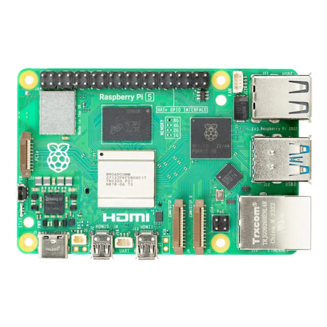
SC1111 - Raspberry Pi 5 4GB SBC 2.4GHz Cortex-A76 | Raspberry Pi | Desktop & Industrial
The Raspberry Pi 5 (SC1111, 4GB) is a single-board computer built upon a 64-bit quad-core 2.4 GHz Arm Cortex-A76 processor with 4GB of RAM on the full-size Raspberry Pi form factor. Per the official product data, its CPU delivers a two to three times increase in performance compared to Raspberry Pi 4, and it is the first full-size Raspberry Pi computer developed with silicon designed in-house by Raspberry Pi. Data verified as of 2026-09-13. A single-board computer (SBC) is a complete computer system integrated onto one printed circuit board, combining processor, memory, I/O interfaces, and power management without the need for a separate motherboard. Within the category hierarchy, the SBC sits between embedded compute modules and full desktop PCs, making it the standard platform for prototyping, education, and industrial edge deployments. Raspberry Pi popularized this form factor, and the Raspberry Pi 5 is its current full-size generation. Key characteristics of the SC1111 include the in-house-developed application processor running at 2.4 GHz, the substantial generational CPU performance uplift over Raspberry Pi 4, and the retained compatibility ethos of the full-size Raspberry Pi layout, which preserves the ecosystem of HAT add-on boards, cases, cameras, and displays that the community and industry have built over multiple generations. From a technical standpoint, the move to custom in-house silicon marks a strategic shift for Raspberry Pi: controlling the SoC design allows tighter integration between CPU, peripherals, and power architecture, which historically translates into better performance per watt and more predictable long-term supply. The quad-core Cortex-A76 core is an Armv8.2-A 64-bit architecture widely deployed in mainstream Android and Chromebook devices, so software toolchains, compilers, and Linux distributions are mature for this target. Typical applications include desktop-class computing and productivity use, industrial automation and edge data logging, robotics control, digital signage, and networked media or AI inference at the edge where local processing avoids cloud dependency. The 4GB memory configuration suits workloads such as lightweight servers, automation controllers, and multi-service IoT gateways. A practical design consideration: verify your power supply meets the board requirements from the official Raspberry Pi documentation before deployment, and confirm HAT mechanical and electrical compatibility when migrating from Raspberry Pi 4, since peripheral interfaces have been updated on this generation. What this page adds beyond the datasheet: a consolidated SC1111 price comparison across authorized distributors (Octopart lists 3 distributors, with PCBX quoting $68.56056 as of 2026-09-13), drop-in and functional alternative analysis within and beyond the Raspberry Pi 5 series, and practical deployment notes for desktop, industrial, and robotics use of this Arm Cortex-A76 single-board computer.
SC1112 - Raspberry Pi 5 8GB SBC, 2.4GHz Cortex-A76 | Raspberry Pi | Edge AI & IoT
The Raspberry Pi 5 (SC1112, 8GB) is a single-board computer built around a 64-bit quad-core 2.4GHz Arm Cortex-A76 processor (Broadcom BCM2712) with 8GB of LPDDR4X SDRAM, delivering two to three times the CPU performance of Raspberry Pi 4 on the standard full-size Raspberry Pi form factor. Data verified as of 2026-09-13. A single-board computer (SBC) is a complete computer fabricated on a single printed circuit board, integrating processor, memory, storage I/O, and connectivity. The Raspberry Pi 5 sits at the top of the Raspberry Pi single-board computer family, which belongs to the broader category of embedded computers, and was developed by Raspberry Pi with its own in-house silicon (BCM2712), a first for the company. Key features of the SC1112 include the 2.4GHz Cortex-A76 quad-core CPU, an 8GB memory configuration (a mid-tier option in the Raspberry Pi 5 series), and the standard 40-pin GPIO header for Hardware Attached on Top (HAT) expansion. Per the official Raspberry Pi product brief, the Pi 5 architecture enables two to three times the speed of other generations. From a technical standpoint, the BCM2712 integrates four Arm Cortex-A76 cores, a high-performance Armv8.2-A-class microarchitecture, with a modern GPU subsystem and I/O fabric. The 8GB LPDDR4X memory pool is the defining differentiator of SC1112 versus the 2GB, 4GB, and 8GB variants, allowing larger working sets for in-memory data processing, multi-container edge deployments, and desktop-class multitasking. Typical applications include edge AI inference and data logging, industrial IoT gateways, robotics control, and desktop-class computing where a compact, low-power Linux computer is required. The 40-pin GPIO header and broad OS support (Raspberry Pi OS, Ubuntu, and others) make it a strong fit for automation and prototyping. A practical design consideration: the higher CPU and memory throughput of Raspberry Pi 5 increases sustained power draw versus Raspberry Pi 4; plan the 5V USB-C power supply and thermal management (heatsink or fan) according to the official Raspberry Pi documentation. Beyond the datasheet, this page provides an SC1112 vs SC1111 (4GB) vs cross-brand SBC comparison, terminal-level 40-pin GPIO wiring reference, design notes, and sourcing information with prices refreshed as of 2026-09-13.
SC1113 - Raspberry Pi 5 16GB SBC, 2.4GHz Cortex-A76 | Raspberry Pi | Edge AI
The Raspberry Pi 5 (SC1113, 16GB) is a single-board computer built around a Broadcom BCM2712 SoC with a 4-core 64-bit Arm Cortex-A76 CPU running at 2.4GHz, 16GB of LPDDR4X SDRAM, and a VideoCore VII GPU, on the standard 85.6 x 56.5mm Raspberry Pi form factor. Data verified as of 2026-09-13. A single-board computer (SBC) is a complete computer system fabricated on a single printed circuit board, integrating the processor, memory, power management, storage interface, and I/O connectors on one board. SBCs sit within the broader category of embedded computers and are widely used where a full PC is unnecessary but general-purpose computing, networking, and expandable I/O are still required. Key features of the SC1113 include the largest memory option in the Raspberry Pi 5 family (16GB LPDDR4X, shared as system and GPU memory), dual 4Kp60-capable HDMI outputs, USB 3.0 and USB 2.0 ports, a PCI Express interface for NVMe storage, dual-band Wi-Fi and Bluetooth, Gigabit Ethernet, and the 40-pin GPIO header that supports HAT expansion boards. The updated power management IC integrates a real-time clock and charging circuitry, and heat dissipation was improved over the Raspberry Pi 4 generation. On the technical side, the VideoCore VII GPU supports OpenGL ES 3.1 and Vulkan 1.2, enabling modern graphics stacks and compute workloads. The faster BCM2712, camera/display interfaces (MIPI), and USB improvements over the predecessor make the Raspberry Pi 5 the most capable board in the Raspberry Pi lineup. The PCIe 2.0 x1 lane allows high-speed NVMe SSDs for storage-heavy applications, while the 40-pin header retains compatibility with the broad HAT ecosystem. Typical applications for the 16GB variant include edge AI inference where large models benefit from higher RAM, desktop computing with many open applications, lightweight virtualization or container hosting, media servers, and industrial gateways aggregating multiple data streams. A practical design consideration: use the recommended 5V/5A USB-C power supply; under sustained multi-core load the board draws significant power, and undervoltage from weak supplies is the most common cause of instability and SD card filesystem corruption. This page adds value beyond the datasheet by cross-referencing SC1113 against other Raspberry Pi 5 memory variants (SC1111 8GB, SC1112 4GB), detailing the 40-pin GPIO terminal map, and giving selection guidance for choosing between RAM tiers based on workload and budget.
SI5365/66-EVB - Clock Multiplier/Jitter Attenuator Eval Kit | Skyworks
The Skyworks Solutions SI5365/66-EVB is an evaluation board for the Si5365 and Si5366 any-frequency precision clock multiplier and jitter attenuator devices, supplied with the board, a cable, a CD containing documentation, and EVB configuration software at an MSRP of $350.00 (as of 2026-10-10). Note that this evaluation kit, along with the Si5365/66 devices it supports, is not recommended for new designs (NRND). An evaluation board (EVB) is a printed circuit assembly that mounts a target integrated circuit together with the supporting power, clocking, filtering, and connector circuitry required to exercise the device in a laboratory environment. EVBs sit within the broader hierarchy of development boards, kits, and prototyping hardware, and they bridge the gap between a datasheet and a production PCB by letting engineers verify jitter, phase noise, lock behavior, and output signal integrity before committing to a layout. The SI5365/66-EVB supports simplified evaluation of the Si5366 jitter-attenuating clock and the Si5356 low-jitter clock multiplier. The Si5365 family provides any-frequency synthesis with user-programmable output frequencies, while the Si5366 adds jitter attenuation for cleaning up noisy reference clocks in synchronized systems such as SONET/SDH, OTN, and synchronous Ethernet equipment. The kit ships with the evaluation board, a USB/interface cable, a CD with documentation and the EVB control software, allowing register-level configuration of loop bandwidths, output dividers, and frequency plans from a PC. This software-driven control flow is the fastest way to characterize the device's phase-noise performance with external test equipment. Typical evaluation scenarios include Telecom line-card clocking, network synchronization (SyncE/PTP) reference generation, and lab prototyping of low-jitter clock trees for high-speed data converters and FPGA/ASIC reference inputs. Design consideration: because the Si5365/66 platform is not recommended for new designs, use this board only to evaluate or support existing designs, and plan a migration path to Skyworks' current-generation timing parts. This page synthesizes distributor pricing, lifecycle status, and kit contents from manufacturer and distributor data not always surfaced in a single datasheet.
SI5367/68-EVB - Si5367/Si5368 Clock Evaluation Board | Skyworks
The Skyworks Solutions SI5367/68-EVB is an evaluation board for the Si5367 low-jitter precision clock multiplier and the Si5368 jitter-attenuating clock, supplied with a board, cable, and CD, and designed for simplified evaluation of any-frequency precision clock multiplication and jitter attenuation. A clock generator evaluation board is a hardware development tool that lets engineers characterize the timing performance of a clock IC before committing to a PCB design. Within the timing hierarchy, it sits under Clock & Timing development tools, which belong to the broader family of semiconductor evaluation kits used alongside clock generators, jitter attenuators, and precision clock multipliers. Evaluation boards expose the IC's inputs, outputs, and configuration interfaces on a ready-made PCB, saving weeks of design effort during device selection and prototyping. The key feature of this kit is dual-device support: it evaluates both the Si5368 jitter attenuating clock and the Si5367 low-jitter clock multiplier on one platform. The Si5367 accepts four clock inputs ranging from 10 MHz to 707 MHz and generates five frequency-multiplied clock outputs ranging from 2 kHz to 945 MHz, with select frequencies to 1.4 GHz, per the Skyworks Si5367 datasheet. This makes it possible to measure phase noise, jitter, and output format behavior across an extremely wide frequency range without soldering or layout work. Technically, the Si5367 family uses a digitally controlled oscillator (DCO)-based architecture with uP-programmable loop parameters, allowing any-frequency synthesis from a simple configuration file loaded over the onboard interface. The evaluation board provides the necessary power regulation, input clock conditioning, and output SMA-style connections so that laboratory instruments such as phase-noise analyzers and oscilloscopes can connect directly. Supplied contents per the distributor datasheet listing are the board, a cable, and a CD containing configuration and documentation. Typical applications include line-card and optical module clock design for SONET/SDH and Ethernet systems, verification of jitter cleanup performance for noisy reference clocks, and lab characterization of frequency plans for FPGA, ASIC, and networking PHY designs requiring sub-picosecond level clocking. A key design consideration: Skyworks marks this evaluation kit as not recommended for new designs (NRND), so use it for evaluating existing designs or for prototyping with the Si5367/Si5368 devices while considering newer Skyworks Si5xx timing platforms for new product development. This page synthesizes distributor pricing, lifecycle status, datasheet links, and practical evaluation guidance not consolidated in the manufacturer datasheet.