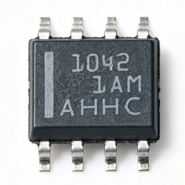
TCAN1051HD
TCAN1051HD - 2Mbps Fault-Protected CAN FD Transceiver | Texas Instruments
Texas Instruments TCAN1051HD is a fault-protected CAN FD transceiver with flexible data-rate support, operating at up to 2 Mbps and meeting the ISO 11898-2:2016 and ISO 11898-5:2007 physical-layer standards. The device is packaged in an 8-pin SOIC for surface-mount PCB assembly. It supports classic CAN and CAN FD communication, making it suitable for industrial controllers, vehicle electronics, robotics, and embedded systems where fault-tolerant bus interfacing is required.
A CAN transceiver is the physical-layer interface between a CAN controller and a CAN bus. It converts controller logic-level TXD and RXD signals into differential CANH and CANL bus levels, while providing receiver filtering, bus-fault protection, and a sleep or standby interface. The TCAN1051HD belongs to the broader CAN interface IC hierarchy, which connects digital controllers and microcontrollers to a robust differential communications network.
Fault protection is the primary system-level feature of the TCAN1051HD. According to the Texas Instruments TCAN1051H data sheet, the device is designed for CAN FD networks operating up to 2 Mbps and can withstand bus-fault conditions that occur during wiring errors, short circuits, or induced transients. The operating-temperature range is -55°C to +125°C, supporting demanding industrial and automotive-grade operating environments when the appropriate ordering variant and qualification are selected.
The device includes a half-duplex CAN communication path, fault-protected bus interfaces, dominant and recessive receiver outputs, and low-power sleep functionality. It meets ISO 11898-2:2016 for high-speed CAN and ISO 11898-5:2007 for CAN FD physical-layer behavior. These standards define the physical signaling, timing, and fault-handling expectations used by compatible CAN controllers and network equipment.
Typical applications include industrial automation controllers, electric-vehicle and vehicle-control modules, robot communication networks, building automation gateways, diagnostic interfaces, and embedded industrial computers. In each case, the transceiver sits between a CAN controller and the differential bus while isolating the controller from the physical CANH and CANL network. Bus termination, common-mode filtering, protection components, and decoupling must be implemented according to the manufacturer data sheet.
For PCB design, place the transceiver close to the connector or bus interface to minimize trace area on CANH and CANL. Use a symmetrical pair routing, controlled return-current paths, and the recommended power and ground decoupling. Keep sensitive logic and analog circuitry away from high-energy bus connections, and verify the selected transceiver's sleep-state, enable, and logic-level behavior against the host controller.
This product page combines device specifications, standards coverage, engineering application guidance, and drop-in replacement analysis. It is intended to support component selection, PCB planning, and qualification decisions without substituting a new footprint or changing the installed eight-pin SOIC land pattern.
询价
联系我们