دوائر التوصيل البيني المتكاملة
الفئات الفرعية
المنتجات (2,300+)

CD4097BE - 20V Dual 8:1 Analog Multiplexer | Texas Instruments
The Texas Instruments CD4097BE is a 20 V dual 8:1 analog multiplexer with internal address decoding, supplied in a 24-pin PDIP package. Each device section provides one multiplexed analog path, and the two sections allow two independent eight-channel selections when their address and enable inputs are driven separately. The verified distributor listing identifies a nominal 240 ohm on-resistance and describes the part as a two-circuit analog switch IC. An analog multiplexer is a semiconductor routing device that selects one of several analog inputs and connects it to a common terminal. In multiplex mode, the selected common terminal receives the active channel; in demultiplex mode, the selected channel terminal receives the common signal. The CD4097B family is digitally controlled while carrying analog signals, placing it between CMOS control logic and external analog front ends. Internal address decoding reduces the control logic required from three address inputs plus an enable input to a binary selection interface. Key verified features include a 20 V maximum supply rating, two 8:1 circuits, eight selection states per circuit, and approximately 240 ohm on-resistance. The manufacturer describes the family as having low on-resistance, low off-leakage, and relatively constant on-resistance across the applied signal range. These characteristics make the mux suitable for routing sensor outputs, measurement inputs, or low-frequency control signals where a compact, reliable selection network is required. The CD4097BE belongs to the CD4000 CMOS logic family and operates from digital address and enable signals. Its 24-pin PDIP package is intended for through-hole PCB assembly rather than high-density surface-mount designs. Because the supplied excerpts do not include complete timing, logic-level, leakage-current, temperature, or absolute-maximum tables, designers should consult the TI CD4097B datasheet before finalizing edge cases. Typical uses include multiplexed sensor acquisition, programmable gain or filter selection, data acquisition systems, instrumentation, and embedded measurement boards. The multiplexer should be placed where the selected signal bandwidth, source impedance, injected noise, and settling time are compatible with the CD4097B. Digital ground and analog return paths should be arranged carefully so control switching transients do not distort the selected measurement. The principal design trade-off is that a multiplexed architecture reduces the number of external analog connections but concentrates signal-routing behavior in one device. Verify the selected channel’s resistance, leakage, charge injection, and settling behavior against the measurement bandwidth. If the analog source has high impedance, use a suitable buffer after the mux or account for the mux impedance in the complete signal path. This product page combines the verified manufacturer and distributor identifiers, package information, and functional context with explicit data gaps for unprovided electrical limits. It is intended to support initial design selection, while the manufacturer datasheet remains the authoritative source for production design decisions and qualification requirements.

CD4097BM - 8:1 CMOS Analog Multiplexer | Texas Instruments
The Texas Instruments CD4097BM is a 20 V, 8:1, single-channel CMOS analog multiplexer with internal address decoding, packaged in a 24-SOIC. Its 240 ohm on resistance, low off leakage, and digital select inputs suit it for routing one analog source among eight channels or distributing one source to eight destinations. A CMOS analog multiplexer is an analog switch controlled by digital logic that connects one common terminal to one selected input or output terminal. The CD4097B family belongs to the CD4000B CMOS logic series and can operate as either a multiplexer or demultiplexer, depending on how the common and channel terminals are connected. Verified device features include low on impedance, low off leakage current, internal binary address decoding, and relatively constant on resistance over the applied signal range. The manufacturer describes the CD4097B as a 20 V, 8:1 differential, one-channel analog multiplexer. The M suffix identifies the listed 24-SOIC ordering variant. The device uses three address inputs to select one of eight channels. In multiplex mode, the selected channel terminal connects to the common terminal; in demultiplex mode, the common terminal becomes the source and the selected channel terminal receives the signal. This arrangement allows a microcontroller or counter to address sensors, measurement inputs, or outputs without a large bank of discrete switches. Typical uses include sensor selection, instrumentation, test and measurement routing, data acquisition, and industrial control. Because the switch path is bidirectional, engineers should verify voltage, current, leakage, and timing limits for the complete signal path. The manufacturer documentation also provides the authoritative pin configuration and electrical limits. For new layouts, place the CD4097BM close to the source and destination circuitry, route the common and selected-channel traces as impedance-sensitive analog nets, and provide adequate bypassing around the supply pins. This page combines verified manufacturer and distributor information with practical routing guidance and sourcing context.

CD4543BF - BCD Seven-Segment LCD/LED Driver | Harris
The Harris CD4543BF is a CMOS BCD-to-seven-segment latch, decoder, and display driver with a 16-CERDIP package. According to the Texas Instruments CD4543B datasheet, it accepts BCD data for displays with segments a through g and decimal point a, and it is designed primarily for liquid-crystal displays while also supporting LED, incandescent, gas-discharge, and fluorescent displays. The device latches decoded display data, reducing input-bus activity during multiplexed operation. A BCD-to-seven-segment decoder is a display-driver subcategory that translates binary-coded decimal information into the seven drive lines used by a numeric display. In the broader electronics hierarchy, the CD4543BF belongs to interface ICs, display drivers, CMOS logic, and digital semiconductors. It sits between a controller or counter and a physical display, allowing a system to present digits without using a microcontroller to generate every segment waveform. The verified manufacturer information identifies CD4543B as functionally similar to the CD4056B when pin 7 is connected to VSS. The family also provides latch, decoder, blanking, and display-driver functions, but detailed timing, voltage, current, and temperature limits were not included in the supplied search extracts. The 16-lead package and CDIP form factor make the CD4543BF suitable for through-hole industrial, educational, instrumentation, and legacy-control designs where a conventional ceramic dual-in-line package is preferred over a surface-mount package. Typical uses include seven-segment LCD modules, multiplexed LED displays, digital counters, panel meters, timers, and embedded industrial panels. When driving LCD segments, the display's drive polarity and common-plane arrangement must match the device specifications. When driving LEDs, segment current, duty cycle, and the number of simultaneously lit digits must be checked against the display and supply limits. A decoder is not a regulated power supply or a high-current constant-current LED driver. The principal design consideration is interface timing. The latch allows the input BCD value to be held while segment outputs are decoded, but the display system must still generate valid strobe and multiplexing signals. Confirm pin assignments, supply voltage range, output drive capability, propagation timing, and electrical limits from the manufacturer datasheet before replacing an existing CD4056B or designing new PCB artwork. This page synthesizes the verified manufacturer classification, distributor availability, package information, family relationship, and application context for CD4543BF. It deliberately distinguishes documented information from parameters that require confirmation from the full datasheet, helping engineers avoid treating a distributor category label as a complete electrical specification.

CH340C - USB to UART Bridge IC, SOP-16 | WCH (Qinheng Micro)
The WCH (Nanjing Qinheng Microelectronics) CH340C is a USB-to-UART bridge controller IC that provides a full-speed USB 2.0 device interface on the USB side and a standard asynchronous serial (UART) interface on the device side, simulating a traditional serial port so that legacy RS-232 applications can be migrated to USB without firmware changes. The 'C' variant integrates the 12 MHz clock generation on-chip, so unlike the CH340G it requires no external crystal or oscillator, simplifying PCB layout and reducing BOM cost for hobbyist and consumer designs. It is offered in a 16-pin SOP-16 package and supports both 3.3 V and 5 V supply operation, making it compatible with 5 V-tolerant microcontroller UARTs and modern 3.3 V MCUs from the same board. Built-in features include full MODEM control signals (RTS, DTR, DCD, RI, DSR, CTS), automatic handshake and flow control, and a hardware full-speed USB 2.0 transceiver. The CH340C is widely deployed as the USB-to-serial converter on Arduino Uno/Nano clones, ESP8266/ESP32 programmer boards, and low-cost serial debug adapters where it replaces more expensive FTDI or Silicon Labs bridges. A USB-to-UART bridge (also called a USB-to-serial converter) is a type of interface IC that bridges a USB host (computer) to a UART peripheral (microcontroller, GPS module, legacy serial device). The hierarchy is: USB bridge > USB-to-UART bridge > serial interface IC > interface controller > integrated circuit. The bridge enumerates as a Virtual COM Port (VCP) on the host OS, so existing PC software treats the USB cable as a legacy COM port without code changes. Key features include on-chip 12 MHz oscillator (no crystal required), 3.3 V and 5 V operating modes selectable via the V3 pin, USB 2.0 full-speed (12 Mbps) compliance, integrated USB termination and pull-up resistors, and built-in power-on reset. Maximum baud rate is 2 Mbps per the WCH datasheet, covering most MCU debug and firmware-flashing workloads. The CH340C uses a CMOS process with an internal SIE (Serial Interface Engine), endpoint FIFO buffer, and UART block. Suspend current is rated at approximately 50 uA per the WCH data, and active supply current is typically 7 mA during full-speed USB traffic - well within bus-powered budgets. Typical applications include Arduino clone boards, ESP-01/NodeMCU programmers, USB-to-TTL debug cables, and industrial serial port expansion where the host PC has dropped native RS-232 ports. The 5 V tolerance also lets the bridge interface legacy 5 V MCUs directly. When designing with the CH340C, route the USB D+/D- pair as a 90-ohm differential pair with a common-mode choke, place the V3-decoupling capacitor close to the pin, and confirm host-OS driver availability - native Windows 10/11 and Linux/macOS support exists, but some legacy Windows installations require the WCH-supplied INF driver. This page synthesizes distributor pricing, verified pin-compatible drop-in variants (CH340B, CH340N, CH340E) in the same SOP footprint family, and practical PCB/design notes not collected in a single spot in the WCH datasheet.
CH340G - USB to UART Bridge IC, SOP-16, 2 Mbps | WCH
The WCH (Nanjing Qinheng Microelectronics) CH340G is a USB-to-UART bridge controller that converts between USB 2.0 full-speed signals and asynchronous serial UART, housed in a 16-pin SOP-16 (SOIC-16) package. It supports 5V and 3.3V supply operation, baud rates from 50 bps to 2 Mbps, and integrates an optional RS-232 assistant mode that inserts an internal inverter on the RXD pin when the R232 pin is driven high. An external 12 MHz crystal is required for the CH340G variant; the CH340C variant in the same family replaces the crystal with an internal oscillator. A USB-to-UART bridge (also called a USB-serial converter) is an interface controller that translates USB packets into asynchronous UART frames and vice versa, allowing microcontrollers that lack native USB (such as the ATmega328P, ESP8266, or older PIC parts) to communicate with a host PC through a standard COM port. USB-UART bridges sit one layer below the USB protocol stack and above the bare UART peripheral, transforming what would otherwise require a complex HID/CDC firmware stack into a transparent virtual COM port. CH340 fits into the broader taxonomy of interface ICs -> bus converters -> USB bridges. Key features of the CH340G include full USB 2.0 full-speed device compatibility, hardware flow control on CTS/RTS, automatic transmitter/receiver buffer management, modem signals (RI, DCD, DTR, DSR), and 5V-tolerant IO when VCC is 5V. The device enumerates as a CDC-class device on Windows/macOS (driver required on Windows) and as a CDC-ACM device on Linux/Android without additional drivers. The SOP-16 footprint is the most widely used package for hobbyist Arduino Nano and NodeMCU/ESP-12E boards. The CH340G uses an external 12 MHz fundamental-mode crystal feeding an internal PLL to derive the 48 MHz USB clock and the configurable UART baud-rate generator. Internal UART FIFOs buffer transmit and receive traffic, and the chip supports common baud rates from 50 bps up to 2 Mbps as well as non-standard rates generated through a divisor setting. The R232 assistant pin enables RS-232 polarity translation in software, eliminating the need for an external MAX232 in many point-to-point designs. Typical applications include Arduino Nano and Arduino Nano-compatible clones, ESP8266/ESP-12E serial programmer boards (NodeMCU, Wemos D1), industrial USB-to-RS232 adapters, USB-to-RS485 converter dongles, and as a low-cost debug serial bridge on custom MCU boards. It is also used in label printers, GPS receivers, and barcode scanners that need USB connectivity for legacy UART peripherals. When designing with the CH340G, ensure the 12 MHz crystal is placed within 5 mm of the XTI and XTO pins with a guard ground to avoid radiated emissions that can fail USB compliance. Decouple VCC with a 100 nF ceramic cap adjacent to pin 16 and a 4.7 uF bulk cap on the 3.3 V rail. The V3 pin should be left floating when using a 5 V supply or tied to a 3.3 V LDO when using a 3.3 V supply. This page synthesizes distributor pricing from LCSC, drop-in pin-compatible alternatives from the CH340 family, and practical design notes not consolidated in the manufacturer datasheet.

CH340N - USB 2.0 to UART Bridge IC, SOP-8 | WCH (Qinheng)
The WCH (Nanjing Qinheng Microelectronics) CH340N is a full-speed USB 2.0 to UART bridge IC housed in an 8-pin SOP-8 package, designed to convert between USB and standard serial (UART) interfaces. It supports 3.3 V and 5 V logic levels, operates over a -20 °C to +70 °C commercial temperature range, and provides serial baud rates up to 2 Mbps. The IC integrates the USB transceiver, oscillator, and UART logic, requiring only minimal external components to add a USB COM port to an embedded design. What is a USB-to-UART bridge? A USB-to-UART bridge IC is a class of interface controller that translates between the USB protocol used by a host PC and the asynchronous serial (UART) interface used by microcontrollers, GPS receivers, and legacy peripherals. These parts sit in the hierarchy: USB-to-UART bridge -> UART controller -> serial interface IC -> interface controller -> integrated circuit. The CH340 family from WCH is one of the most widely deployed low-cost bridges, found on virtually every Arduino-clone board and in countless debug-probe designs. Key features of the CH340N include hardware full-speed USB 2.0 device compliance, automatic USB enumeration without external firmware, support for common baud rates from 50 bps up to 2 Mbps, and built-in MODEM control signals. Its small SOP-8 footprint makes it ideal for space-constrained modules where the larger CH340G (SOP-16) does not fit. The chip needs only an external 12 MHz crystal and a few decoupling parts to provide a complete USB-to-serial solution on a board under 10 mm × 10 mm. Technically, the CH340N uses an internal 3.3 V LDO regulator that can also supply up to ~50 mA to external circuitry from the USB bus, simplifying designs that power a low-current MCU directly from the 5 V USB rail. The UART pins (TXD, RXD, RTS, CTS) are 5 V tolerant when VCC is 5 V, and operate at 3.3 V levels when VCC is 3.3 V. Driver support is included in mainstream Windows, macOS, and Linux kernels, although older Windows builds may need a vendor INF driver. Typical applications include Arduino-clone boards and hobbyist serial debuggers, industrial sensor data loggers, USB-to-RS232 adapter dongles (with an external level translator), USB programming interfaces for low-cost MCUs, point-of-sale terminals, and GPS module debug consoles. The wide 3.3 V / 5 V compatibility lets one design serve both 3.3 V MCUs (e.g., ESP32, RP2040) and 5 V boards (e.g., Arduino Uno) with no level shifting. When designing with the CH340N, place the 12 MHz crystal and load capacitors within 5 mm of the XI/XO pins, route D+/D- as a 90 Ω differential pair, and add a 1 µF bulk capacitor on VCC. For 5 V systems, tie V3 to VCC through a 4.7 kΩ resistor to enable the internal 3.3 V regulator; for 3.3 V systems, leave V3 floating. This page synthesizes distributor pricing, drop-in WCH-family alternatives, and practical design notes not found in the standalone WCH datasheet alone.

CI521 - Modbus TCP Interface Module | ABB | Industrial I/O
The ABB CI521 is a Modbus TCP interface module for the AC500 and S500 distributed I/O platforms, providing a communication bridge between an automation system and field devices. The verified ABB product information identifies CI521-MODTCP as a S500 interface module with a Modbus TCP server, 4 analog inputs, 2 analog outputs, 8 digital inputs, and 8 digital outputs. It is associated with the AC500/S500 system rather than being a standalone semiconductor component, so its package, pinout, electrical ratings, and pricing require additional manufacturer data before a PCB-level replacement can be considered. What is a Modbus TCP interface module? A Modbus TCP interface module is an industrial communication and I/O device that maps serial Modbus-style register data onto Ethernet-based automation equipment. In an AC500/S500 installation, it can distribute process measurements and control commands across a controller, remote I/O, sensors, actuators, and supervisory software. The verified CI521 description lists both analog and digital channels, with digital outputs rated at 24 VDC and 0.5 A, while the analog input and output signal types are identified as voltage, current, and RTD. The CI521-MODTCP configuration provides four analog inputs supporting U, I, and RTD, two analog outputs supporting U and I, eight 24 VDC digital inputs, and eight 24 VDC digital outputs. The product page also states that the system can be extended by up to 10 I/O modules. These are system-level capabilities rather than individual IC specifications, so replacement decisions must account for terminal-unit compatibility, network configuration, channel counts, signal conditioning, controller firmware, and the exact ABB product variant. Because CI521 is an industrial module, the relevant design concerns are network integration, terminal wiring, grounding, channel isolation, environmental limits, and controller configuration rather than semiconductor package pinout. The available search data does not provide verified dimensions, operating temperature, power consumption, Ethernet connector details, isolation ratings, or lifecycle status for the exact CI521 designation. The most reliable approach is to use the ABB CI521-MODTCP documentation and the original system configuration when selecting a replacement. Typical deployments include factory process-control cabinets, remote I/O stations, temperature and pressure monitoring, analog signal acquisition, digital actuator control, and Modbus TCP supervisory communication. A drop-in replacement must be validated against the AC500/S500 platform, terminal-unit arrangement, Modbus register map, channel ratings, and mechanical installation. Generic cross-reference results do not establish those conditions. This page distinguishes the verified CI521-MODTCP identity from unrelated search results for other CI521 references. It also records the provided source URLs, highlights missing technical fields instead of estimating them, and emphasizes that no pin-compatible alternatives were verified. For procurement, contact ABB or an authorized industrial distributor with the complete ordering code, firmware context, and cabinet configuration.

COM20022I3V-HT - 10Mbps 3.3V ARCNET Controller, 48-TQFP | Microchip
The Microchip Technology COM20022I3V-HT is a 3.3V, 10 Mbps ARCNET (ANSI 878.1) embedded network controller with 2Kx8 on-chip dual-port RAM, housed in a 48-pin TQFP (7x7 mm) package. It supports differential media interfaces (RS-485/Backplane variants), consumes 65 mA typical supply current from a 4.5 V to 5.5 V rail, and is rated for the extended industrial temperature range. An ARCNET (ANSI 878.1) controller is a deterministic, token-passing local-area-network protocol controller originally standardized by the ARCNET Trade Association and now widely deployed in industrial, factory, building-automation and transportation networks. Within the hierarchy: ARCNET controller -> network controller -> communication IC -> interface IC -> semiconductor. ARCNET sits alongside protocols such as Ethernet, CAN, and Profibus but is uniquely characterized by its deterministic token-passing media access which guarantees bounded latency - a property valued in real-time control systems where Ethernet's CSMA/CD unpredictability is unacceptable. Key features of the COM20022I3V-HT include automatic detection of multiplexed versus non-multiplexed microcontrollers/microprocessors, an 8-page message support with command chaining for packet queuing, minimal microcontroller and media-interface logic overhead, and flexible media interfaces (differential, RS-485, Backplane, fiber). The integrated 2Kx8 dual-port RAM allows zero-wait-state command chaining without external SRAM, simplifying board layout. The device is built on a mature CMOS process and integrates the entire ARCNET physical (PULSE/1) and data-link layer (token passing) in silicon. Designers connect it to a microcontroller via parallel bus (8-bit multiplexed or non-multiplexed) and to the physical media via a single external transceiver (e.g., a differential line driver). The HT suffix indicates high-temperature (-40C to +85C) operation. Typical applications include industrial/factory automation (PLC backbones, machine networking), building automation (HVAC, lighting control networks), transportation (rail signaling, traffic control), embedded control networks, and any deterministic real-time LAN requiring deterministic latency rather than Ethernet's best-effort behaviour. The 48-TQFP package is footprint-compatible with the broader COM20022I family. When designing with this part, place the external differential transceiver close to the COM20022I3V-HT to minimize stub length, use a 4.7 uF tantalum plus 0.1 uF ceramic bypass on VCC, and observe the recommended reset timing from the manufacturer datasheet. The HT (high-temperature) suffix makes this variant especially suited to outdoor cabinets and industrial enclosures without active cooling. This page synthesizes distributor pricing, same-package alternatives and design notes not found in the manufacturer datasheet.

CP2101 - USB to UART Bridge, QFN-28, 5x5mm | Silicon Labs
The Silicon Labs CP2101 is a single-chip USB-to-UART bridge controller integrating a USB 2.0 full-speed function controller, USB transceiver, oscillator, EEPROM, and asynchronous serial data bus (UART) with full modem control signals in a compact 5 x 5 mm MLP/QFN-28 package. A USB to UART bridge is a type of interface controller IC that allows legacy RS-232/UART peripherals and microcontrollers to communicate with a host PC over USB by transparently translating between the USB protocol and the traditional asynchronous serial data bus format. The CP2101 sits in the broader interface IC category and eliminates the need for external USB controllers, level shifters, or crystal oscillators, drastically reducing BOM count and PCB footprint when adding USB connectivity to embedded designs. Key features include a USB 2.0 full-speed (12 Mbps) compliant transceiver, an integrated 5-to-3 V voltage regulator enabling USB bus-powered or self-powered configurations, an on-chip programmable EEPROM for vendor ID, product ID, serial number, and other descriptor customization, and full modem control signals (RTS, CTS, DTR, DSR, DCD, RI). The device uses a standard COM port driver on Windows, macOS, and Linux, eliminating custom driver development. The CP2101 is implemented in standard CMOS mixed-signal technology and supports data rates from 300 bps up to 921.6 kbps. The 5-to-3 V internal regulator provides up to 100 mA to external circuitry, simplifying bus-powered designs. An internal RC oscillator and an integrated one-time-programmable (OTP) EEPROM replace external components and reduce manufacturing costs. Typical applications include adding USB connectivity to RS-232 legacy equipment, USB-to-UART cables and dongles, microcontroller-to-USB bridges, industrial control adapters, point-of-sale terminals, and embedded development boards. The integrated regulator and EEPROM make it ideal for compact, low-power designs requiring a single BOM-friendly solution. When designing with the CP2101, engineers should follow the recommended decoupling capacitor placement on VBUS and VDD pins and ensure proper grounding of the analog and digital grounds. Note that the CP2101 is a mature product; Silicon Labs recommends CP2102N for all new designs - this is critical for long-term product lifecycle planning. This page synthesizes distributor pricing, drop-in alternatives (CP2102C-A01-GQFN28, CP2102N-A02-GQFN28), and practical design notes not found in the manufacturer datasheet alone.
CP2101-GM USB 2.0 to UART Bridge | Silicon Labs
The Silicon Labs CP2101-GM is a USB-to-UART bridge controller integrating a USB 2.0 full-speed controller, USB transceiver, oscillator, EEPROM, and asynchronous serial interface in a compact 28-QFN package measuring 5 mm by 5 mm. It connects a USB host to legacy UART equipment while adding a compact USB interface and minimizing the external component count required for an RS-232-style design. A USB-to-UART bridge, also called a USB serial interface adapter, converts between USB traffic and asynchronous serial data. It belongs to the interface-controller hierarchy and provides a bridge between a host computer and embedded equipment, industrial controllers, test systems, and legacy serial peripherals. The CP2101 family also includes full modem-control signals, allowing the integrated bridge to serve as a complete USB-to-serial interface rather than only a basic data adapter. Verified distributor information identifies the CP2101-GM as a Silicon Labs USB bridge with a USB 2.0 UART interface in a 28-QFN package. The listed package is 5 mm by 5 mm, and the integrated USB 2.0 full-speed function controller operates without additional external USB components according to the manufacturer-linked Mouser datasheet source. The device is therefore suited to compact boards where a discrete USB transceiver and separate serial interface would increase component count and PCB area. The CP2101 family is intended for updating RS-232 designs to USB with minimal components and PCB space. Typical engineering uses include programming and configuration ports, industrial equipment, instrumentation, data acquisition, and embedded control systems. The integrated oscillator and EEPROM are particularly useful when minimizing external support circuitry is a priority, while the asynchronous UART supports host-to-device serial communication through a standard bridge architecture. The verified data confirms that the CP2101 is a mature product and is not recommended for new designs; the manufacturer-linked documentation identifies the CP2102 as a pin- and software-compatible alternative recommended for new designs. Existing CP2101-GM designs should therefore be evaluated for lifecycle, driver, and supply-chain considerations before committing to long-term production. A replacement must also be checked for exact footprint, electrical limits, firmware, and host-driver behavior rather than relying only on the USB-to-UART function label. For layout, place the device and its supporting components close to the USB connector and keep high-speed USB traces short and continuous. USB differential routing, grounding, decoupling, and connector placement can materially affect signal integrity even though the CP2101 integrates the USB transceiver. The page consolidates verified distributor listings, official-linked documentation, alternative guidance, and design considerations into one procurement-oriented component record.
CP2101-GMR - USB 2.0 to UART Bridge | Silicon Labs
The Silicon Labs CP2101-GMR is a highly integrated USB-to-UART bridge controller with a USB 2.0 interface, 28-QFN 5 x 5 mm package, and integrated USB transceiver. It provides a compact bridge for updating RS-232 designs to USB while requiring minimal external components and PCB space. The device supports a 3 V to 3.6 V supply range and is supplied in tape-and-reel packaging for surface-mount manufacturing. A USB-to-UART bridge is an interface IC that translates USB host traffic into a conventional UART serial stream, allowing legacy serial equipment, embedded controllers, and service ports to communicate through a USB connector. The CP2101 belongs to the USB interface-controller and interface-IC hierarchy, where USB signaling, UART conversion, clocking, and device identification are consolidated into one controller. Its integrated USB transceiver removes the need for external USB transceiver resistors, while its integrated clock eliminates the need for an external crystal in supported configurations. The CP2101-GMR provides 28 QFN pins and includes an integrated 512-byte EEPROM according to the verified distributor and technical search data. The device is identified as a USB-to-UART controller for USB applications and is available in a lead-free, RoHS-compatible package designation. The search data identifies the CP2101 as a mature product that is not recommended for new designs, while the CP2102 is described as a pin- and software-compatible alternative recommended for new designs. Typical uses include USB-to-RS-232 adapters, embedded development systems, industrial equipment, instrumentation, and legacy serial-port upgrades. Designers should evaluate the CP2102 family for new products when appropriate because the verified CP2101 data sheet material identifies CP2101 as mature and points engineers to CP2102 for new designs. Existing CP2101-GMR boards can use the device when its supply, package, driver, and interface requirements remain unchanged. Layout should preserve the exposed-pad thermal and electrical requirements of the 28-QFN package, route USB differential pairs with controlled impedance, and follow the manufacturer’s recommended decoupling and grounding arrangement. For a replacement decision, verify the exact package, pinout, USB power configuration, UART voltage levels, and host-driver behavior rather than relying only on the USB-to-UART function.
CP2101R - USB 2.0 to UART Bridge, 28-VFQFN | Silicon Labs
The Silicon Labs CP2101R is a highly integrated USB-to-UART bridge controller with a 3 V to 3.6 V supply range, USB 2.0 interface, and asynchronous UART capability, supplied in a 28-VFQFN exposed-pad package measuring 5 mm by 5 mm. It provides a compact bridge between a USB host and legacy serial equipment while minimizing the external circuitry and board space needed for a conventional USB-to-RS-232 design. A USB-to-UART bridge is an interface IC that translates USB transactions into a serial data stream and converts the host connection into UART-compatible signaling. In the system hierarchy, the CP2101R belongs to interface ICs and bridge controllers within the broader semiconductor category. It is useful when an embedded product, test fixture, instrument, or accessory must use a USB connector while presenting a serial interface to downstream circuitry. The verified product information identifies USB 2.0 operation, a 3 V to 3.6 V supply range, UART interfacing, and a 28-MLP or 28-VFQFN exposed-pad package. The exposed-pad construction supports heat spreading where internal dissipation or nearby power circuitry requires it, although the supplied data does not provide a thermal resistance value. CP2101-family documentation also describes full-speed USB operation, an integrated USB transceiver, oscillator, EEPROM, and UART functionality; device-specific limits and pin details should therefore be checked against the manufacturer datasheet before layout release. Typical uses include programming and service interfaces for embedded systems, USB-connected control equipment, legacy serial adapters, industrial test fixtures, and developer boards. The UART bridge allows a USB host to communicate with a downstream controller without exposing the legacy serial connector externally. Firmware and driver support must be confirmed for the target operating system, and USB descriptor configuration should be reviewed if the design changes the default device identity. A key design consideration is the exposed-pad footprint. The PCB should follow the manufacturer’s land pattern, preserve solderability during reflow, and provide adequate thermal and signal-return copper. Do not assume that every similarly named CP2101 orderable part is pin-compatible; the package suffix, exposed pad, electrical limits, and USB/UART behavior must be compared explicitly. This page combines the verified CP2101R supply, interface, package, and sourcing references with engineering guidance for USB-to-UART integration. It also records the evidence boundary: detailed electrical limits, pricing tiers, pin names, and lifecycle status were not supplied in the retrieved data and are not guessed here.
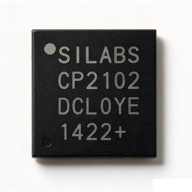
CP2102-GM - USB-to-UART Bridge, QFN-28 | Silicon Laboratories
The Silicon Laboratories CP2102-GM is a highly integrated USB-to-UART Bridge Controller that provides a compact solution for migrating RS-232 designs to USB using a minimum of components and PCB area, packaged in a 5x5 mm 28-pin QFN (QFN-28) with exposed thermal pad. The device integrates a USB 2.0 full-speed function controller, USB transceiver, on-chip oscillator, internal EEPROM, and an asynchronous serial data bus (UART) with full modem control signals, eliminating the need for external USB components. A USB-to-UART bridge controller is a type of bridge IC that sits between a USB host and a legacy UART peripheral, translating USB protocol packets into asynchronous serial bytes and vice versa. In the broader taxonomy, the CP2102-GM belongs to interface ICs (USB bridge controllers), which are a sub-category of communication interface semiconductors that enable protocol translation between modern serial buses and legacy parallel/asynchronous interfaces used in microcontrollers, sensors, and embedded modems. Key features include a 3.0 V to 3.6 V single supply operation, integrated 3.3 V LDO voltage regulator, support for data rates from 300 baud up to 921.6 kbaud, and full modem control signals (RTS, CTS, DTR, DSR, DCD, RI). The internal 1024-byte EEPROM stores customizable product ID, vendor ID, serial number, and GPIO configuration, while royalty-free virtual COM port (VCP) drivers are provided for Windows, macOS, and Linux hosts. The device's architecture combines a USB 2.0 full-speed PHY, an 8051-compatible microcontroller core running the on-chip firmware, and a hardware UART block, with all clock generation handled internally. This integration removes the need for an external crystal, oscillator, or USB termination resistors, dramatically simplifying USB-enabling of legacy microcontroller designs where BOM count is critical. Typical applications include microcontroller-to-USB connectivity on evaluation boards and development kits, industrial point-of-sale terminals, USB dongles for legacy serial equipment, GPS module interfaces, and embedded debug/programming ports. The compact QFN-28 package suits space-constrained PCB layouts where a through-hole DB-9 connector would be impractical. When designing with the CP2102-GM, follow the bus-powered vs self-powered connection diagrams in the Silicon Labs datasheet, since the USB VBUS pin must be routed through a voltage divider when the device is self-powered. Suspend current can be as low as 100 uA, allowing the design to meet USB suspend-current requirements without additional power switching. This page synthesizes distributor pricing, drop-in pin-compatible alternatives, and practical design notes that go beyond what is found in the manufacturer datasheet alone.
CP2102-GMR - USB-to-UART Bridge, QFN-28 | Silicon Laboratories (Tape & Reel)
The Silicon Laboratories CP2102-GMR is a highly integrated USB-to-UART Bridge Controller that provides a compact solution for migrating RS-232 designs to USB using a minimum of components and PCB area, packaged in a 5x5 mm 28-pin QFN (QFN-28) with exposed thermal pad. The device integrates a USB 2.0 full-speed function controller, USB transceiver, on-chip oscillator, internal EEPROM, and an asynchronous serial data bus (UART) with full modem control signals, eliminating the need for external USB components. A USB-to-UART bridge controller is a type of bridge IC that sits between a USB host and a legacy UART peripheral, translating USB protocol packets into asynchronous serial bytes and vice versa. In the broader taxonomy, the CP2102-GMR belongs to interface ICs (USB bridge controllers), which are a sub-category of communication interface semiconductors that enable protocol translation between modern serial buses and legacy parallel/asynchronous interfaces used in microcontrollers, sensors, and embedded modems. Key features include a 3.0 V to 3.6 V single supply operation, integrated 3.3 V LDO voltage regulator, support for data rates from 300 baud up to 921.6 kbaud, and full modem control signals (RTS, CTS, DTR, DSR, DCD, RI). The internal 1024-byte EEPROM stores customizable product ID, vendor ID, serial number, and GPIO configuration, while royalty-free virtual COM port (VCP) drivers are provided for Windows, macOS, and Linux hosts. The device's architecture combines a USB 2.0 full-speed PHY, an 8051-compatible microcontroller core running the on-chip firmware, and a hardware UART block, with all clock generation handled internally. This integration removes the need for an external crystal, oscillator, or USB termination resistors, dramatically simplifying USB-enabling of legacy microcontroller designs where BOM count is critical. Typical applications include microcontroller-to-USB connectivity on evaluation boards and development kits, industrial point-of-sale terminals, USB dongles for legacy serial equipment, GPS module interfaces, and embedded debug/programming ports. The compact QFN-28 package suits space-constrained PCB layouts where a through-hole DB-9 connector would be impractical. When designing with the CP2102-GMR, follow the bus-powered vs self-powered connection diagrams in the Silicon Labs datasheet, since the USB VBUS pin must be routed through a voltage divider when the device is self-powered. Suspend current can be as low as 100 uA, allowing the design to meet USB suspend-current requirements without additional power switching. This page synthesizes distributor pricing, drop-in pin-compatible alternatives, and practical design notes that go beyond what is found in the manufacturer datasheet alone.

CP2102N-A01-GQFN20 USB 2.0 UART Bridge | Silicon Labs
The Silicon Labs CP2102N-A01-GQFN20 is a USB 2.0 full-speed USB-to-UART bridge IC with four digital I/O pins, an integrated USB transceiver, oscillator, and UART, housed in a 20-QFN package measuring 3 mm by 3 mm. According to the Silicon Labs CP2102N data sheet, the device supports a 3 V to 3.6 V supply range and provides an integrated 3.3 V regulator output for compatible USB power designs. A USB-to-UART bridge is an interface controller that converts between USB connectivity and asynchronous serial data. It belongs to the broader hierarchy of interface ICs, USB controllers, USB interface bridges, and data-conversion semiconductors. This device is intended to simplify RS-232-to-USB modernization, firmware-free USB enumeration, and embedded serial connectivity by integrating the required USB and UART functions in one compact component. The CP2102N-A01-GQFN20 combines a USB 2.0 full-speed function controller, USB transceiver, integrated clock, UART, programmable vendor and product identification, serial-number support, and four digital I/O pins. According to the manufacturer data sheet, no external USB components are required for development, and an internal 960-byte programmable ROM stores device identification and descriptor information. The compact package helps reduce board area in space-constrained USB-to-serial designs. The integrated clock removes the need for an external crystal in the referenced USB design application, while the integrated transceiver supports direct USB connectivity. The four digital I/O pins provide additional control or status functions beyond the primary USB and UART interfaces. This integration is valuable when a design needs a small USB-to-UART bridge without implementing USB protocol firmware. Typical applications include industrial control equipment, test and measurement instruments, data loggers, configuration interfaces, serial adapters, embedded development boards, and legacy RS-232 systems converted to USB. The 3 mm by 3 mm package is particularly useful where connector placement and board area are constrained. When designing a board, route USB differential pairs as a controlled-impedance pair and keep the connector, protection components, and transceiver path physically compact. Confirm the exact package pinout and exposed-pad connection in the Silicon Labs data sheet before layout release. Commercial pricing and availability should be checked against distributor records as of 2026-10-22. This page consolidates manufacturer specifications, verified distributor references, cross-reference findings, and practical design considerations for engineers evaluating the CP2102N-A01-GQFN20 USB-to-UART bridge.
CP2102N-A01-GQFN20R USB 2.0 UART Bridge | Silicon Labs (Tape & Reel)
The Silicon Labs CP2102N-A01-GQFN20R is a USB 2.0 full-speed USB-to-UART bridge IC with four digital I/O pins, an integrated USB transceiver, oscillator, and UART, housed in a 20-QFN package measuring 3 mm by 3 mm. According to the Silicon Labs CP2102N data sheet, the device supports a 3 V to 3.6 V supply range and provides an integrated 3.3 V regulator output for compatible USB power designs. A USB-to-UART bridge is an interface controller that converts between USB connectivity and asynchronous serial data. It belongs to the broader hierarchy of interface ICs, USB controllers, USB interface bridges, and data-conversion semiconductors. This device is intended to simplify RS-232-to-USB modernization, firmware-free USB enumeration, and embedded serial connectivity by integrating the required USB and UART functions in one compact component. The CP2102N-A01-GQFN20R combines a USB 2.0 full-speed function controller, USB transceiver, integrated clock, UART, programmable vendor and product identification, serial-number support, and four digital I/O pins. According to the manufacturer data sheet, no external USB components are required for development, and an internal 960-byte programmable ROM stores device identification and descriptor information. The compact package helps reduce board area in space-constrained USB-to-serial designs. The integrated clock removes the need for an external crystal in the referenced USB design application, while the integrated transceiver supports direct USB connectivity. The four digital I/O pins provide additional control or status functions beyond the primary USB and UART interfaces. This integration is valuable when a design needs a small USB-to-UART bridge without implementing USB protocol firmware. Typical applications include industrial control equipment, test and measurement instruments, data loggers, configuration interfaces, serial adapters, embedded development boards, and legacy RS-232 systems converted to USB. The 3 mm by 3 mm package is particularly useful where connector placement and board area are constrained. When designing a board, route USB differential pairs as a controlled-impedance pair and keep the connector, protection components, and transceiver path physically compact. Confirm the exact package pinout and exposed-pad connection in the Silicon Labs data sheet before layout release. Commercial pricing and availability should be checked against distributor records as of 2026-10-22. This page consolidates manufacturer specifications, verified distributor references, cross-reference findings, and practical design considerations for engineers evaluating the CP2102N-A01-GQFN20R USB-to-UART bridge.

CP2102N-A01-GQFN24 USB-to-UART Bridge | Silicon Labs
The Silicon Labs CP2102N-A01-GQFN24 is a USB 2.0 full-speed to UART interface bridge with four GPIOs and separate VDD and VIO pins, housed in a 24-QFN package measuring 4 mm by 4 mm. Designed as part of the USBXpress family, it adds USB connectivity to embedded products without requiring a separate USB transceiver, oscillator, or host-side firmware. The bridge combines a USB controller, USB transceiver, internal oscillator, UART, and four general-purpose I/O functions to reduce board size and design effort. A USB-to-UART bridge is an interface IC that connects a USB host to a serial UART peripheral while handling USB packetization, enumeration, control transfers, and serial data transmission. This device is useful when an existing embedded design needs a compact USB-to-serial path for firmware updates, configuration, diagnostics, logging, or manufacturing test. Its position in the hierarchy is USB interface bridge, then USB-to-UART interface IC, then broader interface IC and semiconductor. The verified ordering information identifies four GPIOs, separate VDD and VIO pins, and a -40 °C to +85 °C temperature range. The package is QFN24, and the product is specified for a 3 V to 3.6 V supply according to the available distributor and datasheet data. The separate VDD and VIO arrangement allows the USB and UART sides to use independently selected supply domains when the host circuit requires voltage-domain flexibility. The four GPIOs add simple control or status functions beyond basic UART communication. Typical uses include industrial control equipment, USB-to-RS-232 design updates, serial adapters, embedded development boards, programmable controllers, and factory test equipment. Because the CP2102N integrates the USB function controller, transceiver, oscillator, and UART, the circuit can be designed with fewer external USB components than a discrete USB implementation. The manufacturer datasheet should be consulted for the exact pin names, exposed-pad connection, capacitor values, voltage sequencing, and USB routing requirements. For PCB implementation, place the device close to the USB connector and maintain short, controlled-impedance USB differential traces. Decouple each applicable supply domain near its pins and follow the datasheet’s recommended footprint and exposed-pad thermal design. Confirm host-driver support, UART voltage levels, cable orientation, and regulatory requirements before releasing a production design. This page combines the verified manufacturer and distributor data with same-package replacement research, application guidance, comparison parameters, and practical implementation notes. It does not infer undocumented specifications or treat functionally similar bridges as pin-compatible replacements.
CP2102N-A01-GQFN24R USB-to-UART Bridge | Silicon Labs (Tape & Reel)
The Silicon Labs CP2102N-A01-GQFN24R is a USB 2.0 full-speed to UART interface bridge with four GPIOs and separate VDD and VIO pins, housed in a 24-QFN package measuring 4 mm by 4 mm. Designed as part of the USBXpress family, it adds USB connectivity to embedded products without requiring a separate USB transceiver, oscillator, or host-side firmware. The bridge combines a USB controller, USB transceiver, internal oscillator, UART, and four general-purpose I/O functions to reduce board size and design effort. A USB-to-UART bridge is an interface IC that connects a USB host to a serial UART peripheral while handling USB packetization, enumeration, control transfers, and serial data transmission. This device is useful when an existing embedded design needs a compact USB-to-serial path for firmware updates, configuration, diagnostics, logging, or manufacturing test. Its position in the hierarchy is USB interface bridge, then USB-to-UART interface IC, then broader interface IC and semiconductor. The verified ordering information identifies four GPIOs, separate VDD and VIO pins, and a -40 °C to +85 °C temperature range. The package is QFN24, and the product is specified for a 3 V to 3.6 V supply according to the available distributor and datasheet data. The separate VDD and VIO arrangement allows the USB and UART sides to use independently selected supply domains when the host circuit requires voltage-domain flexibility. The four GPIOs add simple control or status functions beyond basic UART communication. Typical uses include industrial control equipment, USB-to-RS-232 design updates, serial adapters, embedded development boards, programmable controllers, and factory test equipment. Because the CP2102N integrates the USB function controller, transceiver, oscillator, and UART, the circuit can be designed with fewer external USB components than a discrete USB implementation. The manufacturer datasheet should be consulted for the exact pin names, exposed-pad connection, capacitor values, voltage sequencing, and USB routing requirements. For PCB implementation, place the device close to the USB connector and maintain short, controlled-impedance USB differential traces. Decouple each applicable supply domain near its pins and follow the datasheet’s recommended footprint and exposed-pad thermal design. Confirm host-driver support, UART voltage levels, cable orientation, and regulatory requirements before releasing a production design. This page combines the verified manufacturer and distributor data with same-package replacement research, application guidance, comparison parameters, and practical implementation notes. It does not infer undocumented specifications or treat functionally similar bridges as pin-compatible replacements.
CP2102N-A01-GQFN28 - USB to UART Bridge QFN-28 | Silicon Labs (Tape & Reel)
The Silicon Labs CP2102N-A01-GQFN28 is a USB-to-UART bridge controller from the USBXpress family, providing a single-chip solution for adding USB 2.0 full-speed connectivity to UART peripherals. The device integrates a USB 2.0 full-speed function controller, USB transceiver, on-chip oscillator, and an internal 3.3V LDO regulator in a 28-pin QFN (5x5 mm) package with USB 2.0 UART interface support. A USB-to-UART bridge is a class of protocol converter IC that translates USB signaling into asynchronous serial (UART) signaling, allowing legacy RS-232/RS-485 devices, microcontroller debug ports, and sensor nodes to communicate with a host PC over the USB bus without writing USB firmware. Bridges like the CP2102N live in the hierarchy: USB bridge IC -> interface IC -> connectivity IC -> mixed-signal semiconductor. They are a faster, lower-risk alternative to embedding a USB stack in firmware, and they typically enumerate as a Virtual COM Port (VCP) so existing serial-terminal software works unmodified. The CP2102N-A01 delivers USB 2.0 full-speed (12 Mbps) signaling, supports data rates from 300 baud to 1 Mbaud, integrates a 3.3V LDO with enough headroom to source 100 mA on VIO, and provides GPIO pins plus a hardware reset input (RSTb). The on-chip oscillator and internal voltage regulator remove the need for an external crystal and an external 3.3V rail when the host port supplies 5V bus power. These features let a designer replace a discrete USB-UART implementation with one 5x5 mm QFN. Under the hood, the CP2102N uses a hard-wired USB function-state machine and a programmable baud-rate generator rather than a soft USB stack, which means there is no firmware to maintain on the device itself. The host-side driver (Silicon Labs CP210x VCP) supplies the COM-port abstraction, while the silicon handles NRZI encoding, bit stuffing, packet ACK/NAK, and suspend/resume power management. Typical applications include microcontroller debug and programming adapters (especially for ARM Cortex-M and AVR parts without native USB), industrial sensor-to-USB bridges, point-of-sale terminals, USB dongles for wireless modules, and field-upgrade serial console ports on embedded Linux systems. The wide baud-rate range also supports legacy RS-232 equipment running at non-standard rates. When designing with the CP2102N-A01-GQFN28, observe the bus-powered voltage-divider requirement documented in Silicon Labs AN976: a resistor divider on VBUS is required to bring the 5V supply within the device's absolute-maximum rating. Use the CP210x VCP driver on the host, and respect the 6-byte internal EEPROM signature if you intend to customize USB descriptors (VID/PID/strings). This page synthesizes distributor pricing, drop-in QFN-28 alternatives from both Silicon Labs and competitors, and practical design notes that go beyond the bare datasheet summary.
CP2102N-A01-GQFN28R - USB to UART Bridge QFN-28 | Silicon Labs
The Silicon Labs CP2102N-A01-GQFN28R is a USB-to-UART bridge controller from the USBXpress family, providing a single-chip solution for adding USB 2.0 full-speed connectivity to UART peripherals. The device integrates a USB 2.0 full-speed function controller, USB transceiver, on-chip oscillator, and an internal 3.3V LDO regulator in a 28-pin QFN (5x5 mm) package with USB 2.0 UART interface support. A USB-to-UART bridge is a class of protocol converter IC that translates USB signaling into asynchronous serial (UART) signaling, allowing legacy RS-232/RS-485 devices, microcontroller debug ports, and sensor nodes to communicate with a host PC over the USB bus without writing USB firmware. Bridges like the CP2102N live in the hierarchy: USB bridge IC -> interface IC -> connectivity IC -> mixed-signal semiconductor. They are a faster, lower-risk alternative to embedding a USB stack in firmware, and they typically enumerate as a Virtual COM Port (VCP) so existing serial-terminal software works unmodified. The CP2102N-A01 delivers USB 2.0 full-speed (12 Mbps) signaling, supports data rates from 300 baud to 1 Mbaud, integrates a 3.3V LDO with enough headroom to source 100 mA on VIO, and provides GPIO pins plus a hardware reset input (RSTb). The on-chip oscillator and internal voltage regulator remove the need for an external crystal and an external 3.3V rail when the host port supplies 5V bus power. These features let a designer replace a discrete USB-UART implementation with one 5x5 mm QFN. Under the hood, the CP2102N uses a hard-wired USB function-state machine and a programmable baud-rate generator rather than a soft USB stack, which means there is no firmware to maintain on the device itself. The host-side driver (Silicon Labs CP210x VCP) supplies the COM-port abstraction, while the silicon handles NRZI encoding, bit stuffing, packet ACK/NAK, and suspend/resume power management. Typical applications include microcontroller debug and programming adapters (especially for ARM Cortex-M and AVR parts without native USB), industrial sensor-to-USB bridges, point-of-sale terminals, USB dongles for wireless modules, and field-upgrade serial console ports on embedded Linux systems. The wide baud-rate range also supports legacy RS-232 equipment running at non-standard rates. When designing with the CP2102N-A01-GQFN28R, observe the bus-powered voltage-divider requirement documented in Silicon Labs AN976: a resistor divider on VBUS is required to bring the 5V supply within the device's absolute-maximum rating. Use the CP210x VCP driver on the host, and respect the 6-byte internal EEPROM signature if you intend to customize USB descriptors (VID/PID/strings). This page synthesizes distributor pricing, drop-in QFN-28 alternatives from both Silicon Labs and competitors, and practical design notes that go beyond the bare datasheet summary.
CP2102N-A02-GQFN20 - USB to UART Bridge, QFN-20 | Silicon Labs
The Silicon Labs CP2102N-A02-GQFN20 is a highly integrated USB-to-UART bridge controller in the USBXpress family, packaged in a 20-pin QFN (3x3 mm) with built-in USB 2.0 full-speed function controller, on-chip transceiver, internal oscillator, and Universal Asynchronous Receiver/Transmitter operating from 3.0 V to 3.6 V supply. A USB-to-UART bridge, also called a USB interface IC or USB-serial converter, is a class of mixed-signal device that converts a USB physical layer (USB 2.0 full-speed) into an asynchronous serial interface. It sits in the broader hierarchy of interface ICs (bridge ICs -> protocol converters -> connectivity ICs -> semiconductors) and replaces legacy RS-232 transceivers with a single-chip, driver-supported solution requiring no external USB components. The bridge transparently handles USB enumeration, bulk transfer, and UART signaling so the host MCU firmware can treat the link as a simple COM port or /dev/tty device. Key features of the CP2102N-A02-GQFN20 include four configurable GPIO pins, a battery charger detect function for portable designs, support for data formats from 5 to 8 data bits with or without parity, hardware and software flow control (RTS/CTS, XON/XOFF), and a 1024-byte buffer for high-throughput UART operation. The integrated 3.3 V LDO regulator, on-chip oscillator, and internal pull-up resistors eliminate the need for most external components, shrinking the BOM to a few decoupling capacitors plus optional ESD protection. The architecture is built around a USB 2.0 full-speed (12 Mbps) SIE, an internal 48 MHz oscillator, ROM-based firmware accessed via the Virtual COM Port (VCP) driver or USBXpress direct API, and a flexible UART block with independent TX/R FIFOs. The A02 revision is the recommended replacement for the older A01 revision and is pin-compatible with A01-GQFN20 footprints. The compact 3x3 mm QFN package and minimal external part count make it ideal for space-constrained USB Type-C dongles, embedded debug headers, and industrial sensor interfaces. Typical applications include USB-to-UART debug consoles on MCU development boards, industrial point-of-sale terminals, portable medical USB instrument front-ends, IoT gateways, and field-upgradable firmware service ports. The integrated driver support for Windows, macOS, and Linux VCP modes, combined with Silicon Labs' USBXpress host libraries, accelerates time-to-market for designs that previously required custom USB stacks. When designing with this part, place the 4.7uF VBUS decoupling and 100 nF VDD bypass capacitors as close to the IC pins as possible to meet USB 2.0 signal-integrity requirements. The D+ line typically requires a 1.5 kOhm pull-up to 3.3 V for full-speed device detection, and an external 10 kOhm pull-down on TXD is required for Send-Break signaling.
CP2102N-A02-GQFN20R - USB to UART Bridge, QFN-20 | Silicon Labs (Tape & Reel)
The Silicon Labs CP2102N-A02-GQFN20R is a highly integrated USB-to-UART bridge controller in the USBXpress family, packaged in a 20-pin QFN (3x3 mm) with built-in USB 2.0 full-speed function controller, on-chip transceiver, internal oscillator, and Universal Asynchronous Receiver/Transmitter operating from 3.0 V to 3.6 V supply. A USB-to-UART bridge, also called a USB interface IC or USB-serial converter, is a class of mixed-signal device that converts a USB physical layer (USB 2.0 full-speed) into an asynchronous serial interface. It sits in the broader hierarchy of interface ICs (bridge ICs -> protocol converters -> connectivity ICs -> semiconductors) and replaces legacy RS-232 transceivers with a single-chip, driver-supported solution requiring no external USB components. The bridge transparently handles USB enumeration, bulk transfer, and UART signaling so the host MCU firmware can treat the link as a simple COM port or /dev/tty device. Key features of the CP2102N-A02-GQFN20R include four configurable GPIO pins, a battery charger detect function for portable designs, support for data formats from 5 to 8 data bits with or without parity, hardware and software flow control (RTS/CTS, XON/XOFF), and a 1024-byte buffer for high-throughput UART operation. The integrated 3.3 V LDO regulator, on-chip oscillator, and internal pull-up resistors eliminate the need for most external components, shrinking the BOM to a few decoupling capacitors plus optional ESD protection. The architecture is built around a USB 2.0 full-speed (12 Mbps) SIE, an internal 48 MHz oscillator, ROM-based firmware accessed via the Virtual COM Port (VCP) driver or USBXpress direct API, and a flexible UART block with independent TX/R FIFOs. The A02 revision is the recommended replacement for the older A01 revision and is pin-compatible with A01-GQFN20 footprints. The compact 3x3 mm QFN package and minimal external part count make it ideal for space-constrained USB Type-C dongles, embedded debug headers, and industrial sensor interfaces. Typical applications include USB-to-UART debug consoles on MCU development boards, industrial point-of-sale terminals, portable medical USB instrument front-ends, IoT gateways, and field-upgradable firmware service ports. The integrated driver support for Windows, macOS, and Linux VCP modes, combined with Silicon Labs' USBXpress host libraries, accelerates time-to-market for designs that previously required custom USB stacks. When designing with this part, place the 4.7uF VBUS decoupling and 100 nF VDD bypass capacitors as close to the IC pins as possible to meet USB 2.0 signal-integrity requirements. The D+ line typically requires a 1.5 kOhm pull-up to 3.3 V for full-speed device detection, and an external 10 kOhm pull-down on TXD is required for Send-Break signaling.
CP2102N-A02-GQFN24 USB-UART Bridge | Silicon Labs
The Silicon Labs CP2102N-A02-GQFN24 is a USB 2.0 full-speed to UART interface bridge in a 24-QFN 4 mm by 4 mm package, integrating four digital I/O pins. It supports a 3 V to 3.6 V operating-supply range and is designed to add USB connectivity without requiring a separate USB transceiver, oscillator, or UART controller. A USB-to-UART bridge, also called a USB serial interface adapter or interface bridge, converts a USB host connection into a conventional asynchronous serial data path. Within the semiconductor hierarchy, it belongs to interface ICs and system-interface controllers. This device is part of Silicon Labs' USBXpress family and is intended to reduce firmware complexity, external component count, and development time when replacing an RS-232 design with USB. The CP2102N combines a USB 2.0 full-speed function controller, USB transceiver, oscillator, UART, and four digital I/O pins. USBXpress firmware support allows the host software to present a logical serial port while the bridge handles the USB-to-UART conversion. The 24-QFN package supports compact industrial, embedded, communications, and legacy-equipment designs where board area and USB integration are important. The four digital I/O pins provide additional control or status connections beyond the serial interface. Their exact electrical limits, supported logic levels, and application-specific usage must be taken from the manufacturer datasheet rather than inferred from the package description. Likewise, UART baud-rate limits, transceiver current, and clock requirements are not quantified in the supplied search data and are marked for data completion where applicable. Typical uses include USB-to-UART service ports, embedded debug adapters, industrial controllers, data-acquisition equipment, and update interfaces for existing serial products. The integrated USB 2.0 full-speed controller and internal oscillator reduce the number of external interface components compared with a discrete USB implementation. PCB layout should follow the manufacturer's recommended USB trace and decoupling guidance. Keep the USB differential pair short, controlled, and routed away from noisy analog or switching nodes; place required bypass capacitors close to the supply pins; and verify the exposed-pad or thermal arrangement against the package drawing before release to fabrication. This product-data synthesis combines the verified manufacturer and distributor links, package identity, interface hierarchy, and porting information with practical implementation guidance. It does not invent undocumented electrical limits or cross-brand substitutes that cannot be proven pin-to-pin compatible.
CP2102N-A02-GQFN24R USB-UART Bridge | Silicon Labs (Tape & Reel)
The Silicon Labs CP2102N-A02-GQFN24R is a USB 2.0 full-speed to UART interface bridge in a 24-QFN 4 mm by 4 mm package, integrating four digital I/O pins. It supports a 3 V to 3.6 V operating-supply range and is designed to add USB connectivity without requiring a separate USB transceiver, oscillator, or UART controller. A USB-to-UART bridge, also called a USB serial interface adapter or interface bridge, converts a USB host connection into a conventional asynchronous serial data path. Within the semiconductor hierarchy, it belongs to interface ICs and system-interface controllers. This device is part of Silicon Labs' USBXpress family and is intended to reduce firmware complexity, external component count, and development time when replacing an RS-232 design with USB. The CP2102N combines a USB 2.0 full-speed function controller, USB transceiver, oscillator, UART, and four digital I/O pins. USBXpress firmware support allows the host software to present a logical serial port while the bridge handles the USB-to-UART conversion. The 24-QFN package supports compact industrial, embedded, communications, and legacy-equipment designs where board area and USB integration are important. The four digital I/O pins provide additional control or status connections beyond the serial interface. Their exact electrical limits, supported logic levels, and application-specific usage must be taken from the manufacturer datasheet rather than inferred from the package description. Likewise, UART baud-rate limits, transceiver current, and clock requirements are not quantified in the supplied search data and are marked for data completion where applicable. Typical uses include USB-to-UART service ports, embedded debug adapters, industrial controllers, data-acquisition equipment, and update interfaces for existing serial products. The integrated USB 2.0 full-speed controller and internal oscillator reduce the number of external interface components compared with a discrete USB implementation. PCB layout should follow the manufacturer's recommended USB trace and decoupling guidance. Keep the USB differential pair short, controlled, and routed away from noisy analog or switching nodes; place required bypass capacitors close to the supply pins; and verify the exposed-pad or thermal arrangement against the package drawing before release to fabrication. This product-data synthesis combines the verified manufacturer and distributor links, package identity, interface hierarchy, and porting information with practical implementation guidance. It does not invent undocumented electrical limits or cross-brand substitutes that cannot be proven pin-to-pin compatible.