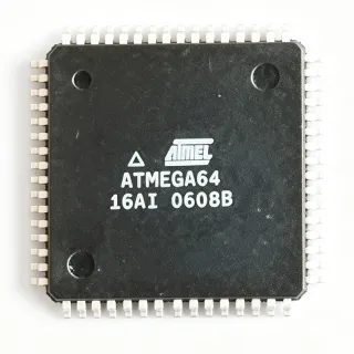
ATMEGA164P-20AQ - 16KB Flash 8-bit AVR MCU 20MHz TQFP-44 | Microchip
MPN: ATMEGA164P-20AQ ✓ نشطATMEGA164P-20AQ نظرة عامة
An 8-bit AVR microcontroller is a Harvard-architecture RISC processor in which flash program memory, SRAM data memory, and I/O peripherals each occupy separate address spaces, allowing most instructions to execute in a single clock cycle. Within the power-management hierarchy, the ATmega family sits between tinyAVR devices and the larger ATmega128x parts, offering 32 general-purpose I/O lines, 32 general-purpose working registers, and a full peripheral set including UART, SPI, and TWI (I2C) serial interfaces.
Key differentiating features include picoPower technology for ultra-low power consumption, read-while-write flash for in-system self-programming, 131 powerful RISC instructions with mostly single-cycle execution delivering up to 20 MIPS throughput at 20 MHz, and two flexible 8-bit/16-bit timers with PWM outputs. An 8-channel 10-bit ADC, analog comparator, programmable watchdog timer with separate on-chip oscillator, and on-chip debug capability via debugWIRE complete the peripheral set.
The picoPower process technology reduces standby currents dramatically: power-down mode consumption is far below standard ATmega parts, making the P-suffix devices suited to battery-powered designs. The extended-temperature (AQ) suffix and green/RoHS packaging suit industrial deployments.
Typical applications include industrial automation nodes, battery-powered metering and sensor transmitters, motor control interfaces, and embedded communication gateways where 16 KB of code space, rich I/O, and low standby current are required.
A key design consideration: the low-frequency crystal oscillator is optimized for very low power and has reduced driver strength compared with ATmega16/32, so crystal load capacitance and ESR must be carefully selected when migrating designs (see Atmel/Microchip application note AVR505).
This page synthesizes distributor pricing, pin-to-pin drop-in alternatives across the ATmega164/324/644 family, and practical migration design notes not consolidated in the manufacturer datasheet.
بدائل مباشرة لـ ATMEGA164P-20AQ — نفس الحزمة، متوافق دبوس بدبوس. تُستثنى القطع ذات الحزم المختلفة التي تتطلب تعديل PCB.
الطرازات في هذه السلسلة
طرازات من نفس السلسلة متوافقة تمامًا مع ATMEGA164P-20AQ (نفس عامل الشكل والبصمة) — يختلف في Package, ADC, EEPROM, SRAM, Core Architecture.
ATMEGA164P-20AU
✅ بديل مباشر📋 بديل مرجعي (غير موجود في الكتالوج)
ATMEGA164A-MU
✅ بديل مباشرتواصل لمعرفة السعر
عرض ورقة البيانات ←ATMEGA324P-20AU
✅ بديل مباشر ⚠️ مواصفات غير مُتحقق منهاتواصل لمعرفة السعر
عرض ورقة البيانات ←ATMEGA644-20AU
✅ بديل مباشرتواصل لمعرفة السعر
عرض ورقة البيانات ←ATMEGA644PA-AU
✅ بديل مباشر ⚠️ مواصفات غير مُتحقق منهاتواصل لمعرفة السعر
عرض ورقة البيانات ←ATMEGA16A-AU
✅ بديل مباشرتواصل لمعرفة السعر
عرض ورقة البيانات ←ATMEGA164P-20AQ الحدود القصوى والخصائص الكهربائية
| Core Architecture | AVR 8-bit RISC |
| Flash Memory | 16 KB (8K x 16) ISP, read-while-write |
| EEPROM | 512 B |
| SRAM | 1 KB |
| Maximum CPU Speed | 20 MHz |
| Supply Voltage Range | 2.7 V to 5.5 V |
| General Purpose I/O | 32 lines |
| General Purpose Working Registers | 32 |
| Instruction Set | 131 instructions, mostly single-cycle |
| MIPS Throughput | Up to 20 MIPS at 20 MHz |
| العلبة | 44-TQFP (10 x 10 mm) |
| درجة حرارة التشغيل | -40C to +85C (extended, A suffix) |
| ADC | 10-bit, 8 channels |
| Serial Interfaces | USART, SPI, TWI (I2C) |
| Low Power Technology | picoPower |
| Watchdog Timer | Programmable WDT with separate oscillator |
| حالة RoHS | Compliant (green package) |
| نوع التركيب | Surface Mount |
تكوين أطراف ATMEGA164P-20AQ
| دبوس 1 | PA0 (ADC0) — Port A bit 0 / ADC channel 0 |
| دبوس 2 | PA1 (ADC1) — Port A bit 1 / ADC channel 1 |
| دبوس 3 | PA2 (ADC2) — Port A bit 2 / ADC channel 2 |
| دبوس 4 | PA3 (ADC3) — Port A bit 3 / ADC channel 3 |
| دبوس 5 | PA4 (ADC4) — Port A bit 4 / ADC channel 4 |
| دبوس 6 | PA5 (ADC5) — Port A bit 5 / ADC channel 5 |
| دبوس 7 | PA6 (ADC6) — Port A bit 6 / ADC channel 6 |
| دبوس 8 | PA7 (ADC7) — Port A bit 7 / ADC channel 7 |
| دبوس 9 | PB0 (XCK0/T0) — Port B bit 0 / USART0 external clock / Timer0 clock input |
| دبوس 10 | PB1 (T1) — Port B bit 1 / Timer1 external clock input |
| دبوس 11 | PB2 (AIN0/INT2) — Port B bit 2 / Analog comparator positive input / External interrupt 2 |
| دبوس 12 | PB3 (AIN1/OC0) — Port B bit 3 / Analog comparator negative input / Timer0 output compare |
| دبوس 13 | PB4 (SS) — Port B bit 4 / SPI slave select |
| دبوس 14 | PB5 (MOSI) — Port B bit 5 / SPI master output slave input |
| دبوس 15 | PB6 (MISO) — Port B bit 6 / SPI master input slave output |
| دبوس 16 | PB7 (SCK) — Port B bit 7 / SPI serial clock |
| دبوس 17 | NC — Not connected (per datasheet) |
| دبوس 18 | VCC — Digital supply voltage |
| دبوس 19 | GND — Ground |
| دبوس 20 | NC — Not connected (per datasheet) |
| دبوس 21 | PC0 (SCL) — Port C bit 0 / TWI serial clock |
| دبوس 22 | PC1 (SDA) — Port C bit 1 / TWI serial data |
| دبوس 23 | PC2 (TCK) — Port C bit 2 / JTAG test clock |
| دبوس 24 | PC3 (TMS) — Port C bit 3 / JTAG test mode select |
| دبوس 25 | PC4 (TDO) — Port C bit 4 / JTAG test data output |
| دبوس 26 | PC5 (TDI) — Port C bit 5 / JTAG test data input |
| دبوس 27 | PC6 (TOSC1) — Port C bit 6 / Timer oscillator input 1 |
| دبوس 28 | PC7 (TOSC2) — Port C bit 7 / Timer oscillator output 2 |
| دبوس 29 | PD7 (OC2) — Port D bit 7 / Timer2 output compare |
| دبوس 30 | PD6 (ICP1) — Port D bit 6 / Timer1 input capture |
| دبوس 31 | PD5 (OC1A) — Port D bit 5 / Timer1 output compare A |
| دبوس 32 | PD4 (OC1B/XCK1) — Port D bit 4 / Timer1 output compare B / USART1 clock |
| دبوس 33 | PD3 (INT1/TXD1) — Port D bit 3 / External interrupt 1 / USART1 transmit |
| دبوس 34 | PD2 (INT0/RXD1) — Port D bit 2 / External interrupt 0 / USART1 receive |
| دبوس 35 | PD1 (TXD0) — Port D bit 1 / USART0 transmit |
| دبوس 36 | PD0 (RXD0) — Port D bit 0 / USART0 receive |
| دبوس 37 | /RESET — Reset input (active low) |
| دبوس 38 | VCC — Digital supply voltage |
| دبوس 39 | GND — Ground |
| دبوس 40 | XTAL2 — System crystal oscillator output |
| دبوس 41 | XTAL1 — System crystal oscillator input |
| دبوس 42 | AREF — ADC analog reference voltage |
| دبوس 43 | AVCC — ADC supply voltage |
| دبوس 44 | AGND — ADC analog ground |
التطبيقات النموذجية
ATMEGA164P-20AQ مناسب لـ 6 التطبيقs: Industrial Automation Nodes, Battery-Powered Metering and Sensing, Embedded Communication Gateways, Motor Control Interfaces, Consumer Embedded Products, Test and Measurement Instrumentation.
Industrial Automation Nodes
The ATMEGA164P-20AQ fits industrial automation and control nodes because its extended -40C to +85C operating range, green industrial-grade packaging, and robust AVR core at up to 20 MIPS handle factory-floor temperature swings and real-time control loops. Its 32 GPIO lines, USART, SPI, and TWI interfaces let one MCU drive sensors, actuators, and an RS-485 or Modbus-over-UART link simultaneously, while the 10-bit ADC digitizes analog process signals with 1024-step resolution. The programmable watchdog timer with a separate on-chip oscillator provides autonomous fault recovery in unattended installations. Running from a 2.7 V to 5.5 V rail, it tolerates noisy 5 V industrial supplies without an external regulator change, and 16 KB of flash accommodates Modbus stacks plus control logic with bootloader headroom for field firmware updates.
موصى به
Battery-Powered Metering and Sensing
The picoPower technology of the ATMEGA164P-20AQ makes it a strong choice for battery-powered meters, dataloggers, and wireless sensor transmitters. Power-down standby current is dramatically lower than standard ATmega parts, and the low-frequency crystal oscillator is specifically optimized for very low power timekeeping in sleep-based duty-cycling designs. The 10-bit ADC samples analog sensors across 8 channels, and the 512 B EEPROM stores calibration constants that survive battery replacement. The wide 2.7 V supply floor means the MCU runs directly from two alkaline cells or a 3 V lithium coin cell without a boost converter. A typical duty-cycle design sleeps in power-down, wakes on watchdog or pin interrupt, measures via ADC, and transmits over USART - the 16 KB flash comfortably hosts this state machine plus a full communication stack.
موصى به
Embedded Communication Gateways
The ATMEGA164P-20AQ serves protocol-conversion gateways where UART, SPI, and TWI traffic must be bridged. The AVR core executes most of its 131 instructions in a single clock cycle, sustaining 20 MIPS at 20 MHz - sufficient to service dual-context UART buffering, SPI slave emulation, and TWI master polling concurrently with interrupt-driven state machines. The 1 KB SRAM buffers packet frames, and read-while-write flash allows a bootloader to rewrite application firmware over the communication link without halting the running program, enabling remote field updates of deployed gateways. Board designers benefit from the 44-TQFP footprint shared across the ATmega164/324/644 family: when traffic volumes grow beyond 16 KB of code, the same PCB accepts an ATMEGA644-20AU with four times the memory and no layout change.
موصى به
Motor Control Interfaces
The ATMEGA164P-20AQ supports small motor control and drive-interface applications through its timer units, which generate multiple PWM channels at hardware level with no CPU load. The 8-bit timers deliver fast PWM suitable for DC motor speed control, while the 16-bit timer provides phase- and frequency-correct PWM for servo and stepper Applications requiring precise pulse widths. The 10-bit ADC reads current-sense shunt voltages or back-EMF feedback for closed-loop speed regulation, and the analog comparator supports zero-crossing detection in sensorless brushless designs. Operating at 5 V with 20 MHz clocking gives 50 ns timer resolution for fine PWM granularity. The extended temperature grade ensures reliable operation inside enclosed drive enclosures where ambient temperatures approach the upper -40C to +85C limit.
موصى به
Consumer Embedded Products
In consumer products such as small appliances, thermostats, remote controls, and toys, the ATMEGA164P-20AQ balances cost and capability. The 44-pin TQFP-44 (10x10 mm) package suits compact two-layer boards, and 32 GPIO lines drive keypads, LED segments, and relays directly at 5 V logic levels. The TWI interface manages capacitive-touch controllers or RTC chips, while the USART serves as a debug or PC-communication port. picoPower modes extend battery life in handheld products, and the green RoHS-compliant package simplifies global regulatory compliance for consumer shipments. With 16 KB of flash, the firmware for a menu-driven user interface plus communication logic fits comfortably, and the family's wide code-footprint pin compatibility (164P/324P/644P) lets product SKUs share one PCB with different memory options for feature tiers.
موصى به
Test and Measurement Instrumentation
The ATMEGA164P-20AQ is well suited to embedded roles within bench-top and handheld test instruments: front-panel control, data acquisition front-ends, and sensor calibration subsystems. The 10-bit ADC with 8 multiplexed channels digitizes probe inputs or auxiliary sensors, and the analog comparator supports threshold-event capture. Precise timing derives from the 16-bit timer clocked by the 20 MHz system clock or an external crystal on XTAL1/XTAL2. The 512 B EEPROM holds factory calibration tables that survive power cycles, and the TWI bus reads out external precision ADCs or reference chips when 10-bit resolution is insufficient. The extended temperature grade supports instruments used outdoors or in environmental chambers, and in-circuit debugging via MPLAB SNAP shortens firmware iteration during instrument development.
موصى به
ملخص المنتجات الموصى بها
بيانات مرجعية هندسية لـ ATMEGA164P-20AQ — المقارنة وإرشادات التصميم ومعلومات الامتثال.
دليل الاختيار
المقارنة مع البدائل
| المعامل | هذا المنتج | ATMEGA164P-20AU | ATMEGA164A-MU | ATMEGA324P-20AU | ATMEGA644-20AU |
|---|---|---|---|---|---|
| Package | 44-TQFP (10x10 mm) | 44-TQFP - same | 44-TQFP - same | 44-TQFP - same | 44-TQFP - same |
| Brand | Microchip Technology (Atmel) | Microchip Technology (Atmel) | Microchip Technology (Atmel) | Microchip Technology (Atmel) | Microchip Technology (Atmel) |
| Flash Memory | 16 KB | 16 KB | 16 KB | 32 KB | 64 KB |
| SRAM | 1 KB | 1 KB | 1 KB | 2 KB | 2 KB |
| EEPROM | 512 B | 512 B | 512 B | 1 KB | 2 KB |
| Maximum CPU Speed | 20 MHz | 20 MHz | 20 MHz | 20 MHz | 20 MHz |
| Supply Voltage | 2.7 V to 5.5 V | 2.7 V to 5.5 V | 1.8 V to 5.5 V | 2.7 V to 5.5 V | 2.7 V to 5.5 V |
| Low Power Technology | picoPower (P-series) | picoPower (P-series) | picoPower A-series | picoPower (P-series) | Standard (non-picoPower) |
أبرز الفروقات
- picoPower low-power modes at same price class (مقابلATMEGA16A-AU)
- Pin-compatible 4x memory upgrade path (مقابلATMEGA324P-20AU)
- Lower cost than high-memory siblings (مقابلATMEGA644-20AU)
- Active A-series successor for new designs (مقابلATMEGA164A-MU)
ملاحظات التصميم
Decouple both VCC pins (18 and 38) with 100 nF ceramic capacitors placed within 5 mm of each pin, plus one 10 uF bulk capacitor near the MCU. Connect AVCC (pin 43) to VCC through a low-pass LC filter (10 uH inductor with 100 nF) when ADC accuracy matters, and tie AREF (pin 42) to ground through a 100 nF capacitor when using the internal reference. Keep the analog ground return (AGND, pin 44) separate from switching-current returns and join at a single star point to protect ADC linearity.
When migrating from ATmega16/32 to the ATMEGA164P, remember that the low-frequency crystal oscillator for Timer2 is optimized for very low power and has reduced driver strength. Per Microchip application note AVR505 (doc8001), the crystal's load capacitance and ESR must be re-verified - a crystal selected for the ATmega16 may fail to start on the ATmega164P. Also confirm fuses for the extended fuse byte (BOD level) and the changed interrupt vector layout, since interrupt registers differ across the migration family.
Estimated: at 5 V and 20 MHz, an ATmega-class AVR draws roughly 10-12 mA active current, giving about 50-60 mW core dissipation plus I/O load (calculate as V x sum of pin currents, max 40 mA per pin, 200 mA total per datasheet absolute maximums). picoPower power-down modes cut this to microamp levels - enable BOD disable in sleep via fuse for lowest current. Size the 5 V supply for peak I/O switching current plus external loads, not just core consumption, and verify brown-out detection level is set above the minimum 2.7 V operating floor.
Keep the XTAL1/XTAL2 crystal traces (pins 41/40) under 10 mm, guard them with ground pour, and place the crystal's load capacitors directly at the pins. Route SPI clock (PB7) and USART lines away from the analog front end; series-terminate 22-33 ohm resistors on fast SPI clock edges if trace lengths exceed 50 mm to reduce ringing and radiated emissions. The TOSC1/TOSC2 32.768 kHz watch crystal on PC6/PC7 is especially sensitive - keep it short and isolated from digital switching loops.
معلومات الامتثال
FindIC listing describes the ATMEGA164P-20AQ as GREEN packaging, indicating RoHS-compliant lead-free construction. REACH, halogen-free, and conflict minerals declarations should be confirmed via Microchip's official compliance documentation.