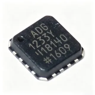
HMC558ALC3BTR - 5.5-14GHz GaAs MMIC Mixer | Analog Devices
MPN: HMC558ALC3BTR ✓ نشطHMC558ALC3BTR نظرة عامة
A double-balanced passive mixer is a frequency-translation building block used in superheterodyne transceivers; it multiplies the radio-frequency (RF) input with a local-oscillator (LO) signal to produce sum and difference intermediate-frequency (IF) outputs, suppressing both the RF and LO leakage at the IF port. Passive Schottky-diode or FET-ring implementations like the HMC558A require no DC bias, which simplifies board-level power architecture but also means they have an inherent insertion loss rather than a conversion gain. Mixers sit beneath the broader RF front-end taxonomy of up/down converters and are essential in any architecture that requires frequency translation.
Key specifications include a broadband RF/LO range from 5.5 GHz to 14 GHz, low conversion loss, and high LO-to-RF and LO-to-IF isolation that is characteristic of the double-balanced topology. The leadless CLCC package eliminates bond wires, improving high-frequency repeatability versus chip-on-board implementations of the bare HMC558 die, and supports high-volume reflow-compatible assembly. The mixer operates from a single supply-free passive configuration, simplifying integration.
The HMC558A chip is fabricated in a GaAs metal-semiconductor field-effect transistor (MESFET) process, leveraging the high electron mobility and low parasitic capacitance of GaAs to achieve low conversion loss and good port-to-port isolation across an octave-spanning band. Internal baluns transform the differential mixer cell to 50-ohm single-ended RF, LO, and IF interfaces, removing the need for external hybrid couplers.
Typical applications include microwave point-to-point and point-to-multipoint radio links, military radar and electronic-warfare receivers and exciters, space and satellite communications payloads, and general-purpose test-and-measurement up/down conversion. When designing with this part, observe the maximum LO drive rating published in the datasheet and ensure the LO source can deliver +15 dBm with adequate harmonic filtering; for evaluation, the device can be ordered in eval-board-ready tape-and-reel packaging (suffix TR) that mates with standard 50-ohm microstrip interfaces.
بدائل مباشرة لـ HMC558ALC3BTR — نفس الحزمة، متوافق دبوس بدبوس. تُستثنى القطع ذات الحزم المختلفة التي تتطلب تعديل PCB.
الطرازات في هذه السلسلة
طرازات من نفس السلسلة متوافقة تمامًا مع HMC558ALC3BTR (نفس عامل الشكل والبصمة) — يختلف في Function, IF Frequency Range, LO Drive Level, Operating Temperature, Package.
HMC558ALC3B
✅ بديل مباشر📋 بديل مرجعي (غير موجود في الكتالوج)
HMC558LC3B
✅ بديل مباشر📋 بديل مرجعي (غير موجود في الكتالوج)
HMC558ALC3BTR-R5
✅ بديل مباشرتواصل لمعرفة السعر
عرض ورقة البيانات ←HMC558ALC3BTR المواصفات
| Part Number | HMC558ALC3BTR |
| Manufacturer | Analog Devices (formerly Hittite) |
| الوظيفة | Double-Balanced Passive Mixer (Up/Down Converter) |
| RF Frequency Range | 5.5 GHz to 14 GHz |
| LO Frequency Range | 5.5 GHz to 14 GHz |
| IF Frequency Range | DC to 4 GHz |
| Conversion Loss (typical) | 7.5 dB at 5.5-10 GHz |
| LO Drive Level | +15 dBm nominal |
| البنية الطوبولوجية | Double-balanced, passive |
| Process Technology | GaAs MESFET MMIC |
| العلبة | 12-pin CLCC (2.9 x 2.9 mm), leadless SMT |
| درجة حرارة التشغيل | -40C to +85C |
| نوع التركيب | Surface Mount |
| Storage Temperature | -65C to +150C |
| حالة RoHS | RoHS Compliant |
| مستوى MSL | 3 (168 hours) |
| Packaging | Tape & Reel (7" reel) |
تكوين أطراف HMC558ALC3BTR
| دبوس 1 | GND — Ground |
| دبوس 2 | GND — Ground |
| دبوس 3 | GND — Ground |
| دبوس 4 | GND — Ground |
| دبوس 5 | GND — Ground |
| دبوس 6 | GND — Ground |
| دبوس 7 | GND — Ground |
| دبوس 8 | GND — Ground |
| دبوس 9 | RF — RF input/output, 50 ohm |
| دبوس 10 | LO — Local oscillator input, 50 ohm |
| دبوس 11 | IF — Intermediate frequency output, 50 ohm |
| دبوس 12 | GND — Ground |
التطبيقات النموذجية
HMC558ALC3BTR مناسب لـ 6 التطبيقs: Microwave Point-to-Point Radio, Radar and Electronic Warfare, Satellite Communications Payloads, Test and Measurement Equipment, Military Microwave Subsystems, Point-to-Multipoint Radio Systems.
Microwave Point-to-Point Radio
The HMC558ALC3BTR fits point-to-point microwave radio links operating across the 5.5-14 GHz common-carrier bands because its RF/LO range directly covers the licensed 6 GHz, 7 GHz, 8 GHz, 10-11 GHz, 12 GHz, and 13-14 GHz allocations used by telecom backhaul. With a +15 dBm LO drive and 7.5 dB typical conversion loss, the part sits cleanly in the IF strip between the RF front-end filter and the demodulator. The double-balanced topology suppresses LO leakage at the antenna port and IF stage, which is critical for meeting regulatory emission masks. Designers value the part because it eliminates an external DC supply, simplifying thermal management in outdoor radio head enclosures.
موصى به
Radar and Electronic Warfare
The HMC558ALC3BTR suits radar receivers and electronic-warfare (EW) systems operating in the 5.5-14 GHz band, including X-band surveillance, warning receivers, and radar-warning applications. Its broadband RF/LO coverage lets one part number span multiple radar bands, reducing BOM count in wideband threat-detection gear. The double-balanced configuration provides high LO-to-RF isolation, which limits leakage that could otherwise be picked up by a sensitive receiver frontend. The GaAs MESFET passive design requires no DC bias, an advantage in size-, weight-, and power-constrained (SWaP) airborne EW pods where reliability and thermal simplicity matter.
موصى به
Satellite Communications Payloads
For satellite-communications (satcom) payload converters, the HMC558ALC3BTR provides frequency translation in the 5.5-14 GHz uplink/downlink bands used by Ku-band and similar space-to-ground links. Its 7.5 dB typical conversion loss is acceptable because downstream gain stages compensate; what's more critical is the part's high port-to-port isolation, which prevents spurious signals from coupling into adjacent transponder channels. The hermetic 12-pin CLCC package is mechanically rugged for vibration-sensitive launch environments. The leadless construction also eliminates bond-wire variation that could detune a high-isolation mixer over temperature.
موصى به
Test and Measurement Equipment
In laboratory bench-top instruments and modular RF test equipment, the HMC558ALC3BTR is used as a general-purpose upconverter or downconverter for signal generators, spectrum-analyzer front ends, and vector-network-analyzer (VNA) stimulus chains. Its broadband 5.5-14 GHz coverage lets one mixer serve multiple instrument bands without band-specific part replacement. The +15 dBm LO drive requirement integrates easily with the LO synthesizers already present in these instruments. Test engineers benefit from the absence of DC supply, which removes the need for bias-tee networks that could otherwise complicate calibration routines.
موصى به
Military Microwave Subsystems
Military microwave subsystems - including EW jammers, direction-finding receivers, and datalinks - use the HMC558ALC3BTR for broadband frequency translation in the 5.5-14 GHz range. Its GaAs MESFET passive topology is established in Mil-spec hardware, and the part's wide operating-temperature range (-40C to +85C) suits outdoor and vehicular platforms. The double-balanced configuration's high LO suppression is essential for co-site operation with adjacent high-power transmitters. Using a leadless ceramic package also aligns with the long-term reliability expectations of defense procurement programs.
موصى به
Point-to-Multipoint Radio Systems
Point-to-multipoint (PMP) radios serving last-mile broadband access often operate in the 5.5 GHz, 10.5 GHz, or 13 GHz bands; the HMC558ALC3BTR covers all of these in a single part number, simplifying inventory across multi-band base-station designs. Its 7.5 dB typical conversion loss enables tight IF chain budgets in cost-sensitive base-station architectures. The mixer's high LO-to-IF isolation protects adjacent base-station sectors from interference. Combined with a +15 dBm LO drive and zero DC supply, the part fits the small-form-factor, low-power demands of outdoor-mounted subscriber units.
موصى به
ملخص المنتجات الموصى بها
بيانات مرجعية هندسية لـ HMC558ALC3BTR — المقارنة وإرشادات التصميم ومعلومات الامتثال.
دليل الاختيار
المقارنة مع البدائل
| المعامل | هذا المنتج | HMC558ALC3B | HMC558LC3B | HMC558ALC3BTR-R5 |
|---|---|---|---|---|
| Package | 12-pin CLCC (2.9x2.9 mm) | 12-pin CLCC (2.9x2.9 mm) - same | 12-pin CLCC (2.9x2.9 mm) - same | 12-pin CLCC (2.9x2.9 mm) - same |
| Brand | Analog Devices | Analog Devices | Analog Devices (Hittite legacy) | Analog Devices |
| RF Frequency Range | 5.5 GHz to 14 GHz | 5.5 GHz to 14 GHz | 5.5 GHz to 14 GHz | 5.5 GHz to 14 GHz |
| LO Drive Level | +15 dBm | +15 dBm | +15 dBm | +15 dBm |
| Conversion Loss (typ) | 7.5 dB @ 5.5-10 GHz | 7.5 dB | 7.5 dB | 7.5 dB |
| Topology | Double-balanced passive | Double-balanced passive | Double-balanced passive | Double-balanced passive |
| Process Technology | GaAs MESFET | GaAs MESFET | GaAs MESFET | GaAs MESFET |
| Packaging Format | Tape & Reel (TR) | Tray (no TR) | Tray (no TR) | Tape & Reel (R5 qty) |
أبرز الفروقات
- Broadband 5.5-14 GHz passive mixer with no DC supply requirement (مقابلHMC558LC3B)
- Tape-and-reel packaging aligned with high-volume SMT lines (مقابلHMC558ALC3B (tray pack))
- Lower-cost user equivalent in same footprint (مقابلHMC558ALC3BTR-R5)
ملاحظات التصميم
Place the HMC558ALC3BTR on a controlled-impedance 50-ohm microstrip or grounded coplanar waveguide (GCPW) substrate with continuous ground beneath the part. Keep RF, LO, and IF traces short and well-decoupled; the leadless CLCC package expects a well-grounded paddle. Vias should form a dense ground fence around the part to suppress substrate-mode coupling and improve port-to-port isolation above ~10 GHz.
Drive the LO port from a source capable of +15 dBm at the device reference plane, accounting for any board-level losses between the LO generator and the pin. Harmonics of the LO source can leak through the mixer's LO-to-IF path; place a low-pass filter on the LO feed when spurious content is critical. Use a small attenuator pad on the LO input (3 dB or 6 dB) to stabilize the drive level if the source amplitude is not well controlled.
Do not exceed the absolute maximum LO drive rating (consult the datasheet table). Operating below +15 dBm will degrade conversion loss and isolation noticeably. Ensure all ports are properly DC-blocked when interfacing with DC-coupled test equipment, since the IF port is rated for DC to 4 GHz. When measuring conversion loss, calibrate out the loss of any external baluns or filter components between the device and the test port.
معلومات الامتثال
RoHS3 compliant per Analog Devices datasheet HMC558A and PartGenie listing. REACH unaffected per PartGenie. Not AEC-Q100 qualified (tier is RF military/aerospace rather than automotive). MSL 3 (168 hours) per PartGenie.