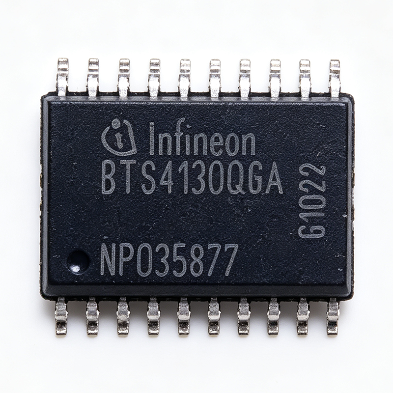
Quick Answers: What Is the BTS4130QGAXUMA1 and What Does It Deliver?
The BTS4130QGAXUMA1 is an Infineon quad-channel Smart High-Side Power Switch in a 20-pin PG-DSO-20-32 surface-mount package. It integrates four N-channel MOSFETs with an internal charge pump, each rated for 2.1 A continuous load current at 130 mOhm typical on-state resistance per channel. The device operates from a 6 V to 18 V supply, clamps load-dump transients at 45 V typical, and carries AEC-Q100 automotive qualification. The part is active in the Infineon portfolio, and XAIPART holds 99,999 units with a minimum order quantity of 1; pricing is $3.92 per unit at quantity 1 and $1.86 per unit at quantity 2,500 as of 2026-09-16.
Engineers specify this component for one reason: it collapses a discrete high-side driver chain into a single IC. Four protected output channels, four logic inputs, and one diagnostic feedback pin replace four MOSFETs, four gate-drive networks, and the external protection circuitry a discrete design needs. The BTS4130QGA family uses N-channel MOSFETs with an internal charge pump rather than P-channel devices, which delivers lower R_DS(on) per silicon area and tighter current-limit accuracy.
Verified core specifications
| Parameter | Verified Value |
|---|---|
| Manufacturer | Infineon |
| Product type | Quad Smart High-Side Power Switch |
| Number of channels | 4 |
| Topology | High-side N-channel MOSFET with charge pump |
| Continuous load current per channel | 2.1 A |
| On-state resistance R_DS(on) per channel | 130 mOhm typical |
| Operating supply voltage | 6 V to 18 V (extended to 28 V transient) |
| Overvoltage clamp (load dump) | 45 V typical |
| Junction temperature range | -40 C to +150 C junction |
| Automotive qualification | AEC-Q100 qualified |
| Protection features | Current limit, overtemperature shutdown, overvoltage clamp, reverse battery |
| Diagnostic output | Status feedback pin |
| Package | PG-DSO-20-32 (20-pin DSO, 7.50 mm width) |
| Mounting type | Surface mount |
| MSL level | 3 (per JEDEC J-STD-020) |
| RoHS status | Compliant |
Stock, MOQ and tiered pricing
| Quantity | Unit Price (USD, as of 2026-09-16) |
|---|---|
| 1+ | $3.92 |
| 10+ | $3.48 |
| 100+ | $2.96 |
| 500+ | $2.55 |
| 1,000+ | $2.18 |
| 2,500+ | $1.86 |
Availability is immediate for small quantities. XAIPART lists 99,999 units in stock with an MOQ of 1, and the base price is $1.86 as of 2026-09-16. The full pin table, mechanical drawing, and ordering variants live on the BTS4130QGAXUMA1 product page.
How Do You Design the BTS4130QGAXUMA1 Into a 12 V Automotive Load?
Designing with a smart high-side switch is mostly a matter of respecting four boundaries: the supply window, the logic interface, the thermal budget, and the fault-reporting path. The BTS4130QGAXUMA1 gives you verified numbers for each.
Step 1: Confirm the supply window and transient environment
The operating supply range is 6 V to 18 V, extended to 28 V transient, with a 45 V typical overvoltage clamp that absorbs load-dump pulses in 12 V automotive systems. Below 6 V, the undervoltage lockout disables the outputs to protect the load. That behavior matters during cold-crank: an output that drops out below 6 V is safer than one that tries to drive a lamp with a partially enhanced MOSFET.
The 28 V transient rating also opens a non-automotive door. The same device is usable as a quad 24 V PLC digital output module switching loads up to 2.1 A per channel, and the PROFET family provides logic inputs and diagnostic feedback on the same harness as the load wires.
Step 2: Drive the INx logic inputs directly from the MCU
Pins 2, 6, 13, and 17 (IN1 through IN4) are active-high logic inputs that a 3.3 V or 5 V microcontroller can drive directly, with no level shifter required. Each input maps to one output: IN1 to OUT1 (pin 1), IN2 to OUT2 (pin 5), IN3 to OUT3 (pin 12), and IN4 to OUT4 (pin 16). Because the inputs are independent, you can PWM one channel for dimming while holding another channel static, or switch all four simultaneously.
PWM dimming at 200 Hz is supported through the INx logic pins for daytime running light brightness control. Keep the drive trace short and away from the OUTx power traces to limit coupling into the logic return.
Step 3: Use the status pin for diagnostics
Pin 7 (ST) is the status and diagnostic feedback output. It reports short-to-ground, open-load, and overtemperature faults back to the module microcontroller for OBD-II diagnostics, and reports stall conditions when a DC motor draws abnormal current, which is directly useful for window-lifter and seat-positioner diagnostics. On the heating-element side, the same pin signals open-circuit faults from a broken heating wire to the climate-control ECU.
Treat ST as a shared fault line for the four channels. Design the MCU firmware to poll ST after each channel state change so a slow-developing thermal fault is not masked by a normal switching event.
Step 4: Size copper for a 150 C junction limit
The device is rated to a +150 C junction. Because the R_DS(on) of an N-channel MOSFET has a positive temperature coefficient, the resistance you measure cold is not the resistance that generates heat at the end of a soak. The datasheet-derived rule of thumb is roughly 1.7x at 150 C junction, which turns 130 mOhm typical into about 221 mOhm hot.
Run the conduction-loss math at both ends of the temperature range. At 25 C junction and the full 2.1 A per channel, each channel dissipates I squared times R_DS(on) = (2.1 A) squared x 0.130 ohm = 0.573 W. Four channels running simultaneously dissipate about 2.29 W. At a hot junction, the per-channel figure rises to about 0.97 W and the four-channel total to about 3.9 W.
That is the number that sizes the heatsink copper area under the PG-DSO-20-32 body. Spend the layout budget on a wide Vbb and GND copper pour before you spend it on anything else; the ground pins at 3, 10, 14, and 19 and the supply pins at 4, 11, 15, and 20 exist precisely so the package can dump heat into the plane.
Step 5: Handle inductive loads and reverse battery
The integrated inductive-load clamp handles the back-EMF of a de-energizing solenoid, protecting both the switch and the harness from transients. For loads that need less than the full 2.1 A, the current limit can be derated to match the specific solenoid pull-in and hold currents.
Reverse-battery protection is intrinsic through the body diode, so the external Schottky diode that a discrete MOSFET design requires is not needed. Note that the reverse-battery function is a device-level capability; always include reverse-battery protection at the module input as a system-level safeguard. Overtemperature shutdown with auto-restart and per-channel current limiting round out the protection set, so no external fuses are required for the four load paths.
Finally, respect the moisture sensitivity level. MSL 3 per JEDEC J-STD-020 means the parts ship dry-packed and carry a floor-life limit after the bag is opened. Tape-and-reel boards that run long shift patterns should treat the reflow profile and bake schedule as part of the design, not an afterthought.
What Are the Drop-In Alternatives to the BTS4130QGAXUMA1?
Substitution decisions in this family turn on three things: channel count, package footprint, and R_DS(on). The table below compares only parts present in the verified XAIPART alternative set.
| Parameter | BTS4130QGAXUMA1 | BTS4180N | VNQ5E160KTR | TPS4H160-Q1 |
|---|---|---|---|---|
| Manufacturer | Infineon | Infineon | STMicroelectronics | Texas Instruments |
| Architecture | Quad smart high-side switch | Same family and pinout as BTS4130QGAXUMA1 | Quad high-side switch | Quad smart high-side switch |
| Continuous current per channel | 2.1 A | Same family/pinout; per-channel rating not stated in the alternative data set | 3.5 A | 1 A |
| R_DS(on) per channel | 130 mOhm typical | ~80 mOhm per channel, about 38% lower | Not stated in the alternative data set | Not stated in the alternative data set |
| Package | PG-DSO-20-32 | Same family/pinout (drop-in) | PowerSSO-24 | HTSSOP-20 |
| Drop-in on an existing PG-DSO-20-32 footprint | Reference part | Yes | No - PCB rework required | No - PCB rework required |
The only true drop-in option in this set is the Infineon BTS4180N. It shares the family and pinout and drops R_DS(on) from 130 mOhm to roughly 80 mOhm per channel, a reduction of about 38%. If your design is thermally limited rather than current limited, that resistance reduction is the single most effective change you can make without touching the PCB layout.
Cross-brand options are real but not free. The STMicroelectronics VNQ5E160KTR is a quad high-side switch rated at 3.5 A per channel in a PowerSSO-24 package, which is higher current than the BTS4130QGAXUMA1 but a different footprint, so it is not a drop-in replacement. For automotive lighting modules that need four independent channels, the 4 x 2.1 A arrangement of the BTS4130QGAXUMA1 covers headlight low beam, high beam, daytime running light, and turn indicator from one IC, whereas the VNQ5E160KTR would require board rework for the extra current headroom.
The Texas Instruments TPS4H160-Q1 is a quad smart high-side switch at 1 A per channel in an HTSSOP-20 package. It is also a cross-package option and carries less than half the per-channel current of the BTS4130QGAXUMA1, so it fits only lower-load body-electronics nodes.
Two substitution traps are worth flagging. The BTS4120N is a dual-channel device, not quad, so it cannot replace the BTS4130QGAXUMA1 on channel count alone. The BTS4140N is typically a single-channel higher-current variant in the same PROFET family; channel count, package (DSO-20 versus DPAK), and current rating are the key differentiators. Always verify channel count, R_DS(on), and package pinout before substituting. Browse related devices in the power MOSFET drivers category.
What Is the Market Position and Supply Situation of the BTS4130QGAXUMA1?
The BTS4130QGAXUMA1 is listed as active in the Infineon portfolio. That lifecycle status matters more than any single specification for a body-control-module design, because automotive platforms run seven to ten years and a last-time-buy notice mid-program is far more expensive than a higher unit price at the start.
Supply is currently deep. XAIPART shows 99,999 units in stock with an MOQ of 1, which means prototype and pilot-build quantities are available without a factory allocation. For production volumes of 10,000 pieces or more, contact Infineon or an authorized distributor directly to confirm factory allocation; lead time is typically 12 to 16 weeks from the factory for tape-and-reel orders.
Unit economics scale predictably. At quantity 1 the part is $3.92; at quantity 100 it is $2.96; at quantity 1,000 it is $2.18; and at quantity 2,500 it is $1.86, all as of 2026-09-16. Volume breaks typically continue downward at the 5,000 and 10,000 tiers, so a formal RFQ through authorized channels is the right move for production pricing.
The compliance picture is complete for automotive sourcing: AEC-Q100 qualification, RoHS compliance, and MSL 3 per JEDEC J-STD-020. Automotive qualification covers Grade-0 stress requirements including load-dump, jump-start, and reverse-battery tests, which is what allows the part to sit in under-the-hood and body-electronics modules.
Detailed market-share, design-win, and second-source qualification data for this specific MPN is not part of the verified data set used for this article and should be confirmed with the manufacturer before it is quoted in a sourcing decision.
What Should Buyers Watch in High-Side Switch Trends Through 2026?
Three shifts are visible directly in the verified specifications of this part and its alternatives.
First, integration keeps absorbing discrete circuitry. One PG-DSO-20-32 device replaces four discrete high-side MOSFET circuits and four fuses in a body control module, and relay replacement removes audible click and contact bounce while cutting PCB area substantially compared with electromechanical relays. Every generation of smart high-side switch pushes more of the protection and diagnostic burden into silicon, which means the BOM line count falls but the layout and thermal work becomes concentrated under one package.
Second, diagnostics are becoming a first-class requirement, not an option. The status feedback pin on the BTS4130QGAXUMA1 reports short-to-ground, open-load, and overtemperature faults, and it distinguishes a stalled DC motor from a normal inrush. As OBD-II and functional-safety expectations tighten, parts without a diagnostic path will be designed out of body-electronics nodes regardless of price.
Third, thermal margin is the new differentiator. The R_DS(on) spread across the alternatives in this article runs from roughly 80 mOhm (BTS4180N) to 130 mOhm typical (BTS4130QGAXUMA1), and that 38% difference translates directly into copper area, junction temperature headroom, and the ability to run all four channels at full load. At 2.1 A per channel, 130 mOhm produces 0.573 W per channel at 25 C, and the same current at a 150 C junction produces roughly 0.97 W per channel. Buyers specifying for worst-case ambient should model both numbers, not just the cold one.
Finally, cross-package equivalence is not equivalence. The VNQ5E160KTR at 3.5 A per channel in PowerSSO-24 and the TPS4H160-Q1 at 1 A per channel in HTSSOP-20 both require PCB rework, so a second-source strategy built on them is a re-spin, not a drop-in. Keep the BTS4180N on the approved-vendor list if pin-compatible dual sourcing is a program requirement. For cross-checking availability and pricing across the family, start from the BTS4130QGAXUMA1 listing and compare against the automotive high-side switch selection guide.
Comments
Be the first to comment.
🔐 Please sign in to post a comment.
Don't have an account? Sign up