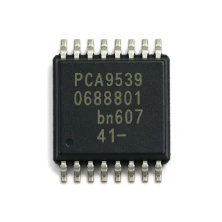
PCA9554APW - 8-Bit I2C GPIO Expander | NXP
MPN: PCA9554APW ✓ সক্রিয়PCA9554APW সারাংশ
An I/O expander is a semiconductor interface device that translates serial I2C commands into parallel digital signals. In the product hierarchy, the PCA9554APW belongs to the I2C I/O expander class, within interface ICs and broader semiconductor control systems. Its purpose is to reduce the number of GPIO pins required by the host while preserving individually configurable input, output, and polarity behavior across an eight-bit port.
Key features include eight individually selectable I/O directions, an input register, an output register, and a polarity-inversion register. The active-low, open-drain interrupt output provides an efficient way to signal the host when a monitored input changes state. Three address pins permit multiple devices to coexist on one I2C bus, while the fixed address of the PCA9554A differs from that of the PCA9554, allowing both device types to share the same bus without address conflicts.
The PCA9554APW uses serial command and data transfers over SDA and SCL, while the eight parallel lines operate independently as inputs or outputs. The operating supply range of 2.3 V to 5.5 V makes the device suitable for systems using 2.5 V, 3.3 V, or 5 V logic. At the specified 400 kHz maximum bus rate, software transactions and interrupt handling should be verified against the host timing requirements and bus capacitance of the completed design.
Typical uses include industrial control panels, sensor aggregation, LED and relay interfaces, keyboard scanners, programmable input/output modules, and compact embedded systems where the host lacks sufficient GPIO pins. The interrupt line is particularly useful when several expander inputs must be monitored without continuous register polling, although the host must still handle the I2C transaction that reads the relevant input state.
Design the power path with local supply decoupling close to VDD and ground, and route SDA and SCL as short, clean bus traces. Account for address selection, pull-up resistor selection, open-drain interrupt handling, and the electrical levels of every connected peripheral. Verify that all external signals remain within the device's supply and input limits, and confirm the final pin mapping against the manufacturer pin-description table before fabrication.
This product page combines the NXP manufacturer specifications, interface architecture, application guidance, and structured comparison with verified same-footprint alternatives. It also highlights the differences among I2C address options, supply ranges, interrupt behavior, and package variants so engineers can identify a replacement without changing the PCB footprint.
এর জন্য ড্রপ-ইন বিকল্প PCA9554APW — একই package, pin-to-pin compatible। ভিন্ন package-এর যেসব পার্টে PCB rework প্রয়োজন সেগুলো বাদ দেওয়া হয়েছে।
এই সিরিজের ভ্যারিয়েন্ট
একই সিরিজের মডেল যেগুলো drop-in compatible PCA9554APW (একই form factor এবং footprint) — পার্থক্য রয়েছে Package.
PCA9554BPW
✅ ড্রপ-ইন📋 রেফারেন্স বিকল্প (ক্যাটালগে নেই)
PCA9554CPW
✅ ড্রপ-ইন📋 রেফারেন্স বিকল্প (ক্যাটালগে নেই)
PCA9554PW
✅ ড্রপ-ইনমূল্যের জন্য যোগাযোগ করুন
ডেটাশিট দেখুন →PCA9554APWR
✅ ড্রপ-ইন📋 রেফারেন্স বিকল্প (ক্যাটালগে নেই)
TCA9554APWR
✅ ড্রপ-ইন📋 রেফারেন্স বিকল্প (ক্যাটালগে নেই)
PCA9554APW বিশেষণ
| Device Type | 8-bit I2C-bus/SMBus parallel I/O expander |
| Number of I/O Pins | 8 pins |
| I2C Bus Speed | 400 kHz |
| অপারেটিং সাপ্লাই ভোল্টেজ | 2.3 V to 5.5 V |
| Interrupt Output | Active-low, open-drain |
| Configuration Register | 8-bit input/output selection register |
| Input Register | 8-bit input register |
| Output Register | 8-bit output register |
| Polarity Inversion Register | 8-bit active-high or active-low polarity selection register |
| Address Configuration | 3 address pins |
| Fixed I2C Address | Different from PCA9554 |
| প্যাকেজ | TSSOP-16 |
| অপারেটিং তাপমাত্রা | -40 C to +85 C |
| মাউন্টিং টাইপ | Surface mount |
| Bus Interface | I2C and SMBus |
| I/O Configuration | Each pin individually selectable as input or output |
PCA9554APW পিন কনফিগারেশন
| পিন 1 | A0 — Address input A0 |
| পিন 2 | A1 — Address input A1 |
| পিন 3 | A2 — Address input A2 |
| পিন 4 | VDD — Positive supply voltage |
| পিন 5 | SCL — Serial clock input |
| পিন 6 | SDA — Serial bidirectional data line |
| পিন 7 | INT — Active-low open-drain interrupt output |
| পিন 8 | GND — Ground connection |
| পিন 9 | P0 — General-purpose I/O port 0 |
| পিন 10 | P1 — General-purpose I/O port 1 |
| পিন 11 | P2 — General-purpose I/O port 2 |
| পিন 12 | P3 — General-purpose I/O port 3 |
| পিন 13 | P4 — General-purpose I/O port 4 |
| পিন 14 | P5 — General-purpose I/O port 5 |
| পিন 15 | P6 — General-purpose I/O port 6 |
| পিন 16 | P7 — General-purpose I/O port 7 |
সাধারণ ব্যবহার
PCA9554APW এর জন্য উপযুক্ত 6 অ্যাপ্লিকেশনs: Industrial Control Panel I/O, Sensor Aggregation Module, LED and Relay Control Interface, Keyboard and Matrix Scanner, Programmable Digital Interface Module, Embedded Automotive Control Interface.
Industrial Control Panel I/O
The PCA9554APW fits industrial control panels where a host controller needs more digital connections than its package provides. Its eight I/O lines can operate as individually configured inputs for switches and status signals or as outputs for indicator and command circuits. The 2.3 V to 5.5 V range supports common industrial logic levels, while the active-low open-drain interrupt reduces polling when panel events require immediate attention. Address pins permit expansion with additional compatible devices. Designers should confirm logic-level compatibility, provide local decoupling, select appropriate SDA and SCL pull-ups, and isolate external field wiring where required.
সুপারিশকৃত
Sensor Aggregation Module
PCA9554APW is useful in sensor aggregation modules that collect several digital sensor alarms or threshold flags alongside an analog or communication controller. Each of the eight ports can be configured for input operation, and the input and polarity registers let firmware interpret active-high or active-low sensor outputs. The interrupt line can notify the host of a changed input while the 400 kHz I2C interface remains available for register access. For dependable operation, check every sensor's output voltage against the 2.3 V to 5.5 V device range, account for bus pull-up values, and place the device close enough to reduce susceptibility to noise.
সুপারিশকৃত
LED and Relay Control Interface
The PCA9554APW can serve as the low-voltage control plane for LED indicators, relay drivers, and latching control logic in compact embedded equipment. Its eight configurable outputs reduce the number of host GPIO pins, and the polarity-inversion register simplifies handling of active-low driver circuits. The I2C bus operates up to 400 kHz, allowing the host to update several outputs efficiently. External transistors or driver ICs remain necessary when a load exceeds the device's output capability. Engineering review should address relay-coil transients, LED current limiting, output-driver topology, supply decoupling, and the open-drain interrupt's pull-up requirement.
সুপারিশকৃত
Keyboard and Matrix Scanner
PCA9554APW can expand a host controller's available lines for keyboard, switch-matrix, and front-panel scanning. Eight inputs or outputs support matrix rows and columns, while configuration and polarity registers simplify firmware setup for active-low keypads. The interrupt output can signal a detected matrix change before the host performs a complete scan. The I2C transaction remains short because the device operates as an 8-bit parallel port on the other side of the bus. Layout considerations include keeping SDA and SCL away from switch-node edges, ensuring pull-up values suit the bus voltage and capacitance, and confirming that the selected logic levels meet the device's input and output limits.
সুপারিশকৃত
Programmable Digital Interface Module
PCA9554APW is appropriate for configurable digital I/O modules used in test fixtures, educational equipment, and compact automation controllers. Eight software-controlled ports allow the same hardware design to support input monitoring or output control. The three address pins enable expansion when the host bus requires several identical modules, and the PCA9554A address differs from the non-A PCA9554 to permit mixed deployments. Firmware must initialize direction, output, and polarity registers according to the intended startup state. Engineers should validate connector protection, logic translation, cable-length effects, bus pull-ups, and reset behavior before deploying the module outside a controlled bench environment.
সুপারিশকৃত
Embedded Automotive Control Interface
PCA9554APW can support low-voltage embedded control interfaces that require additional digital lines beyond the host microcontroller. Its eight configurable ports, 2.3 V to 5.5 V range, and -40 C to +85 C operating range are useful for temperature-controlled or industrialized electronics. Automotive qualification status should be confirmed separately for the exact ordered variant and supplier documentation. The interrupt function can reduce host polling for switch or status events. In implementation, review the host's 3.3 V or 5 V levels, transient environment, connector protection, grounding, decoupling, and all safety requirements; the I/O expander does not replace external protection for exposed wiring.
সুপারিশকৃত
সুপারিশকৃত পণ্যের সারসংক্ষেপ
এর জন্য ইঞ্জিনিয়ারিং রেফারেন্স ডেটা PCA9554APW — তুলনা, ডিজাইন গাইডেন্স এবং কমপ্লায়েন্স তথ্য।
নির্বাচন গাইড
বিকল্পের সাথে তুলনা
| পারামিটার | এই পণ্য | PCA9554BPW | PCA9554CPW | PCA9554PW | PCA9554APWR | TCA9554APWR |
|---|---|---|---|---|---|---|
| Package | TSSOP-16 | TSSOP-16 | TSSOP-16 | TSSOP-16 | TSSOP-16 | TSSOP-16 |
| Brand | NXP Semiconductors | NXP Semiconductors | NXP Semiconductors | NXP Semiconductors | Texas Instruments | Texas Instruments |
| I/O Count | 8 bits | 8 bits | 8 bits | 8 bits | 8 bits | 8 bits |
| Bus Interface | I2C and SMBus | I2C and SMBus | I2C and SMBus | I2C and SMBus | I2C and SMBus | I2C and SMBus |
| Fixed Address Relationship | PCA9554A address differs from PCA9554 | PCA9554B address differs from PCA9554 | PCA9554C replaces PCA9554A | PCA9554 address differs from PCA9554A | PCA9554A address | PCA9554A-compatible address |
| Configuration Registers | Configuration, input, output, and polarity inversion | Configuration, input, output, and polarity inversion | Configuration, input, output, and polarity inversion | Configuration, input, output, and polarity inversion | Configuration, input, output, and polarity inversion | Configuration, input, output, and polarity inversion |
মূল পার্থক্যসমূহ
- Shares an I2C bus with non-A PCA9554 devices (বনামPCA9554PW)
- Documented direct NXP family migration path (বনামPCA9554CPW)
- Lower-voltage Texas Instruments alternative available (বনামTCA9554APWR)
ডিজাইন নোট
Place the PCA9554APW close to the I2C controller and the devices using the expanded port. Keep SDA and SCL traces short, route them away from switch-node and relay-coil edges, and provide the required bus pull-ups. The address inputs should have deliberate connection and routing so each device has a defined address in the completed system.
Add local supply decoupling at VDD and connect the ground return directly to the device ground. Verify that external pull-ups and attached peripherals do not inject current beyond the device's supply limits. If the interrupt line is shared, size its pull-up for the aggregate sink current and account for all connected nodes rather than treating it as an isolated signal.
Do not assume that the PCA9554A and non-A PCA9554 share an I2C address. Firmware must also initialize the configuration register, output register, and polarity register in the intended sequence to avoid transient output states. For relay or LED loads, use suitable external drivers and transient protection rather than driving the load directly from the expander.
Use the numbered manufacturer pin table to assign all 16 TSSOP connections and preserve the package orientation mark in the PCB library. The interrupt is open-drain and requires a pull-up, while SDA is a bidirectional open-drain-style bus line. Check connector pin naming, isolation boundaries, and exposed-cable interfaces so ground returns and protection devices are placed close to the entry point.
কমপ্লায়েন্স তথ্য
Explicit compliance statements for the exact PCA9554APW orderable configuration were not included in the manufacturer product information. Obtain current declarations from NXP before using the part in a regulated design.