LED Drivers
Products (53)
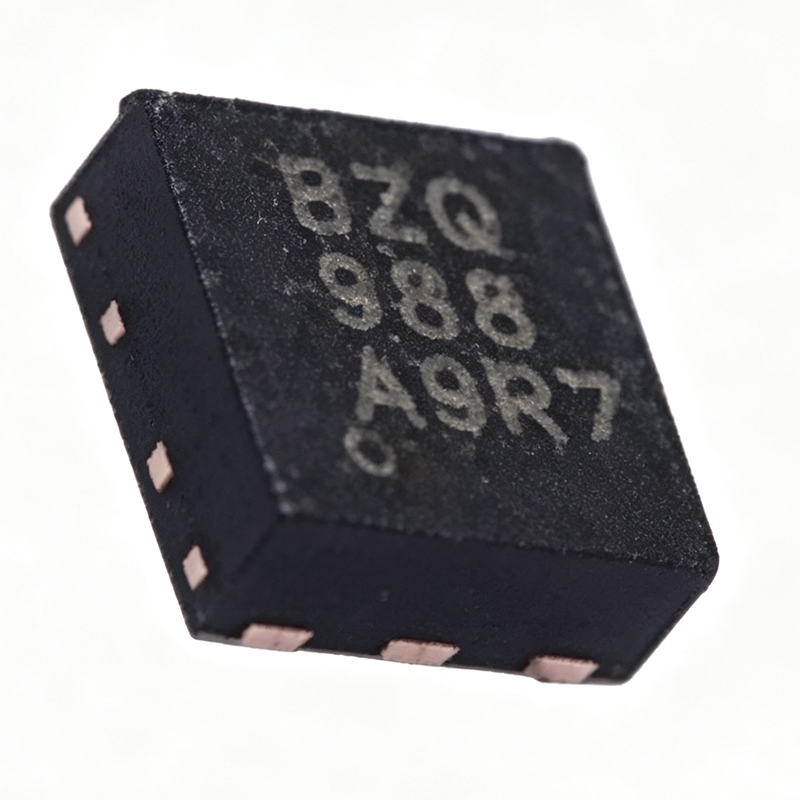
TPS61160DRVR - Boost White LED Driver 18V | Texas Instruments
The Texas Instruments TPS61160DRVR is a white LED driver boost converter with digital and PWM brightness control, delivering up to 10 series LEDs from a 2.7 V to 18 V input, with a 40-V rated integrated switch FET and 700 mA switch current limit in a 2-mm x 2-mm 6-pin WSON (DRV) package. An LED boost driver is a switching regulator (part of the DC-DC converter family of power management ICs) that steps a lower input voltage up to the higher voltage needed by a series LED string. Because LED brightness is proportional to forward current rather than voltage, boost LED drivers such as the TPS61160 regulate current through the string via a low-side sense resistor, providing constant-current operation independent of LED forward-voltage variation. Key features include a 600 kHz fixed switching frequency that shrinks the external inductor and capacitors, 26 V open-LED protection that clamps output overvoltage if the LED string fails open, and a 200 mV current-sense feedback reference that minimizes sense-resistor power loss and improves efficiency. Maximum duty cycle is 93%, supporting high step-up ratios. Technically, the integrated 40-V power MOSFET eliminates an external switch FET, cutting BOM count and layout area. Brightness control is flexible: apply a direct PWM signal, or use the single-wire digital interface that accepts PWM on the CTRL pin for stepless dimming without a dedicated MCU PWM output. Typical applications are LCD backlighting for smartphones, tablets, and portable navigation devices, plus general constant-current LED illumination powered by single-cell Li-ion or multi-cell alkaline/NiMH batteries. Design consideration: the 26 V open-LED protection clamp of the TPS61160 (38 V on the TPS61161) sets the maximum LED string voltage; verify the worst-case summed LED forward voltage stays safely below the clamp over temperature. Pricing cited as of 2026-09-01. This page synthesizes distributor pricing, drop-in alternatives, and practical design notes not found in the manufacturer datasheet.

TPS92691 - Multi-Topology LED Driver | Texas Instruments
The Texas Instruments TPS92691 is a versatile multi-topology LED driver controller designed for step-up (boost), step-down (buck), SEPIC, and flyback topologies. It integrates a rail-to-rail current sense amplifier, enabling accurate LED current regulation across a wide range of applications. The device operates with a fixed-frequency peak current mode control scheme, with programmable switching frequency, slope compensation, and soft-start timing. It supports both analog and PWM dimming, making it suitable for automotive, industrial, and general lighting systems. An LED driver is a power management IC that regulates the current flowing through one or more LEDs, ensuring consistent brightness and protecting the LEDs from current surges. The TPS92691 belongs to the family of switching LED drivers, which use inductive or capacitive energy storage to efficiently convert input voltage to the required LED current. This controller sits between the power source and the LED string, providing closed-loop regulation and dimming capabilities. Key features of the TPS92691 include a wide input voltage range, programmable switching frequency up to 1 MHz, and a rail-to-rail current sense amplifier that allows low-side or high-side sensing. The device also features an internal 10-µA soft-start current source, an external soft-start capacitor for controlled startup, and a COMP pin that is clamped to the SS pin until LED current nears regulation. These features enable smooth startup and stable operation across varying load conditions. The TPS92691 is available in a 16-pin HTSSOP (PWP) package, which provides a compact footprint with exposed thermal pad for improved heat dissipation. The device is designed for high-efficiency operation, with typical efficiencies above 90% in boost and buck configurations. It also includes protection features such as thermal shutdown and overcurrent protection, enhancing system reliability. Typical applications include automotive LED headlights, daytime running lights, industrial LED lighting, and backlighting for displays. The device's flexibility in topology and dimming methods makes it a preferred choice for designers seeking a single controller for multiple LED driver designs. When designing with the TPS92691, it is important to select appropriate external components such as the inductor, MOSFET, and sense resistor to meet the desired output current and efficiency. Proper PCB layout, including minimizing parasitic inductance and ensuring adequate thermal management, is critical for optimal performance.

TPS92691-Q1 - 65V AEC-Q100 LED Driver Controller | TI
The Texas Instruments TPS92691-Q1 (TPS92691QPWPTQ1) is an automotive-qualified multi-topology LED driver controller supporting boost, buck, buck-boost, SEPIC, Cuk, and flyback topologies. It operates from a wide 4.5 V to 65 V input and integrates a 65-V rail-to-rail current sense amplifier with better than ±3% LED current accuracy over a junction temperature range of +25°C to +140°C and a 0 V to 60 V output common-mode range, enabling both high-side and low-side current sensing. The device is supplied in a 16-pin HTSSOP (PWP) package. An LED driver controller is a power management IC that regulates current through LED strings using a switching regulator architecture. Within the power management IC hierarchy, it sits between generic DC-DC controllers and dedicated constant-current LED drivers, adding dimming control, fault protection, and LED-specific features. Peak current mode control is a control technique in which the switch current is sensed and compared against an error-amplifier-derived threshold on a cycle-by-cycle basis, giving inherent cycle limiting and simple loop compensation. Key features include fixed-frequency peak current mode control with programmable switching frequency, programmable slope compensation for stable operation at duty cycles above 50%, programmable soft-start timing to limit inrush current, and a dedicated PWM dimming input that linearly varies LED brightness by modulating the duty cycle of the voltage applied to the PWM pin. Analog dimming is also supported, allowing flexible brightness control in automotive lighting systems. Architecturally, the integrated high-voltage current sense amplifier is the differentiating block: by tolerating a 60 V common-mode input, it removes the need for a dedicated low-side sense resistor path in high-rail strings and simplifies short-circuit diagnostics. The controller generates gate drive for an external MOSFET, so output power is set by external components rather than IC limits. Typical applications include automotive headlights, daytime running lights (DRL), fog lamps, LED backlighting, and industrial lighting driven from 12 V, 24 V, or 48 V automotive and industrial buses. Design consideration: choose the switching frequency and slope compensation together - higher frequency shrinks the inductor but increases switching loss; slope compensation must be set based on the sensed inductor current downslope to avoid subharmonic oscillation at duty cycles above 50%.

XDPL8105XUMA1 - Digital Flyback LED Driver IC | Infineon
The Infineon XDPL8105XUMA1 is a digital single-stage flyback controller IC with high power factor and primary-side regulation designed for cost-effective constant-current LED drivers. It operates from 100-277 VAC input with >90% efficiency, supports a switching frequency range of 3 kHz to 180 kHz, and is housed in an 8-pin PG-DSO-8 (SOIC-8) surface-mount package. The XDP digital platform combines primary-side regulation with active PFC, eliminating the need for an optocoupler and secondary-side feedback components. A flyback controller is a switch-mode power supply (SMPS) topology regulator that stores energy in the primary winding of a coupled inductor during the ON-time of the switch and delivers it to the secondary winding during the OFF-time. Flyback controllers fall under the broader category of AC-DC converters, which in turn belong to power management integrated circuits. Single-stage flyback topologies are widely used in LED lighting because they integrate power factor correction (PFC) and output current regulation into one power stage, reducing BOM cost and PCB area versus two-stage solutions. Key features of the XDPL8105 include integrated digital control state machine, primary-side constant-current regulation without optocoupler, >0.9 power factor at full load, adaptive dimming curve support (linear, quadratic, exponential), flicker-free operation, and built-in protection features (over-temperature, over-current, over-voltage, input under-voltage). The device supports both analog and digital dimming interfaces, making it compatible with industry-standard 0-10V and DALI control gear when paired with external interface circuitry. From an architecture standpoint, the XDPL8105 uses Infineon's XDP digital signal processor hardware engine, which executes parameter-set firmware that can be customized via the XDPL8105 graphical configuration tool. This digital core measures the primary-side current and auxiliary winding voltage to compute the secondary-side output current, achieving regulation accuracy typically within ±2% without secondary-side sensing. The 8-pin package exposes VIN, GND, CS (current sense), AUX (auxiliary winding), DRV (gate driver), DIM (dimming input), VCC, and NC pins. Typical applications for the XDPL8105 include cost-optimized LED downlights, LED panels, LED troffers, outdoor luminaires, and isolated offline LED drivers in the 5-100 W output power range. It is also suitable for flicker-free retrofit bulbs and smart-lighting front-end converters where high power factor compliance (EN 61000-3-2 Class C) is required. When designing with the XDPL8105, attention must be paid to the transformer design (leakage inductance, primary inductance, turns ratio), the snubber network selection, and the CS resistor value. The Infineon reference design RDR-704 is recommended as the starting point for any new LED driver layout. This page synthesizes distributor pricing, parametric alternatives, and practical design notes not found in the Infineon datasheet, helping engineers select, source, and implement the XDPL8105 in production LED luminaire designs.

XDPL8219XUMA1 - Flyback PFC LED Driver Controller | Infineon
The Infineon XDPL8219XUMA1 is a digital flyback controller IC with integrated Power Factor Correction (PFC), housed in a PG-DSO-8-41 package and designed for constant-voltage LED lighting and AC/DC supplies. It delivers <100 mW standby power consumption, PF >0.9 across the universal AC input range (90 Vrms to 305 Vrms), and THD <10% for enhanced harmonic compliance. The device targets Secondary-Side Regulated (SSR) constant-voltage LED driver topologies used in luminaires up to 100 mA output current capability with built-in no-dimming operation. A flyback controller is a switching power-supply control IC that regulates an isolated DC output by switching a primary-side MOSFET and using a transformer to galvanically isolate the load. Constant-voltage (CV) flyback LED drivers add an active PFC stage that shapes the input current to follow the line voltage, achieving high PF and low THD as mandated by regulatory standards such as IEC 61000-3-2. The XDPL8219 integrates PFC control directly into the flyback controller, eliminating a separate PFC stage and simplifying the BOM for cost-sensitive LED lighting designs. Key features of the XDPL8219 include an integrated 600 V high-voltage startup cell that removes the need for an external startup resistor network, secondary-side regulated constant-voltage output via digital control, and enhanced THD/PF correction algorithms that operate across a wide load range. A UART-based digital interface enables parameter tuning, in-system firmware updates, and telemetry, supporting rapid design iteration. The combination of digital control and analog PWM peripherals yields high efficiency, low standby power, and robust protection against abnormal line conditions. Technically, the controller uses Infineon's XDP (eXtremely Dense Platform) mixed-signal architecture with an embedded 8-bit core, on-chip digital compensation loops, and adaptive valley-skipping modulation for efficiency optimization at light loads. The device supports DC input voltages from 127 V to 431 V (post-rectified high-voltage DC bus), making it suitable for both AC mains-powered luminaires and DC-bus lighting such as solar or battery-fed installations. Built-in protections include over-temperature, over-current, over-voltage, and brown-out detection. Typical applications include indoor LED downlights, panel lights, ceiling luminaires, smart-home lighting fixtures, and constant-voltage AC/DC adapters where high PF, low THD, and low standby are required. The device is also used in DC-bus industrial lighting such as 24 V or 48 V architectural systems. For dimmable designs, a primary-side controlled dimming variant may be considered. When designing with the XDPL8219, pay close attention to the primary MOSFET voltage rating versus the reflected output voltage and the leakage inductance spike. The PG-DSO-8-41 package requires proper thermal copper-pour design to dissipate controller losses. Use Infineon's reference design files and the XDPL8219 design guide for transformer sizing, snubber selection, and feedback loop tuning. This page synthesizes distributor pricing, cross-brand availability, and practical design notes beyond the manufacturer datasheet.