LEDドライバ
製品 (129)
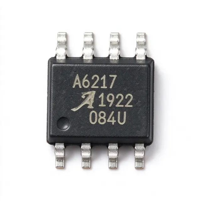
A6217KLJTR-1-T - 1.5A 48V PWM Dimmable Buck LED Driver | Allegro
The Allegro MicroSystems A6217KLJTR-1-T is an automotive-grade, constant-current, PWM-dimmable buck regulator LED driver IC that delivers up to 1.5 A of true-average output current, supplied in an 8-pin SOIC-EP (exposed pad) package with tape-and-reel packaging. Its key specifications include a 6 V to 48 V input supply range, integrated power MOSFET switch, cycle-by-cycle current limit, and enable/PWM dimming via a direct logic input or power-supply voltage, all qualified to AEC-Q100. A buck LED driver is a switching converter that steps down a higher DC bus voltage to a lower, regulated LED forward voltage while actively maintaining average output current (rather than output voltage) as the controlled quantity. Constant-current regulation protects LED strings from thermal runaway, brightness drift, and catastrophic overcurrent when individual LED forward voltages vary with temperature. Buck regulators sit within the broader power management IC family used wherever DC LED strings must be driven from a higher-voltage supply such as 12 V, 24 V, or 48 V industrial/automotive buses. Key differentiating features of the A6217KLJTR-1-T include AEC-Q100 automotive qualification, true average output current control (rather than peak current), 1.5 A continuous output over temperature (the A6217KLJTR-T variant delivers 3 A), and integrated cycle-by-cycle protection. The exposed thermal pad provides a low thermal resistance path, essential when dissipating (VIN - VLED) x ILED at high duty cycles in 24 V automotive body-electronics applications. Architecturally, the A6217 uses a peak-current-mode control loop with an external sense resistor and an internal compensation network. The high-side integrated MOSFET simplifies PCB layout by eliminating external switching transistors, while the integrated low-side synchronous rectifier (when enabled) improves efficiency versus a simple diode-rectified buck. PWM dimming is implemented by modulating the EN/PWM pin, allowing high-contrast dimming down to very low duty cycles. Typical end-system applications are automotive exterior lighting (DRLs, fog lamps, turn signals), interior ambient lighting, architectural and signage LED strips, industrial machine-vision illuminators, and emergency-vehicle strobe systems. The 48 V maximum input makes it suitable for trucks, buses, and industrial 48 V bus architectures. When designing with this device, calculate worst-case power dissipation as (VIN_max - VLED) x ILED and verify junction temperature using the SOIC-EP thermal pad. Place the input bulk capacitor directly at the VIN pad and route the LED string return through the high-side sense resistor to the CS pin for accurate current sensing. This page synthesizes distributor pricing, AEC-Q100 application guidance, and practical design notes not consolidated on the Allegro product page, giving automotive and industrial LED-driver engineers a single reference.

A6217KLJTR-T - 3A Automotive Buck LED Driver | Allegro
The Allegro MicroSystems A6217KLJTR-T is an automotive-grade, constant-current PWM-dimmable buck (step-down) switching regulator LED driver that delivers up to 3 A of output current in an 8-pin SOIC-EP (exposed pad) package. The IC accepts input voltages from 9 V to 46 V (typical automotive bus rails include 9 V, 12 V, 15 V, 18 V, and 24 V systems) and regulates a constant LED current that is set by an external sense resistor, eliminating the need for binning or current-setting calibration in production. A buck LED driver is a switching DC-DC converter whose output stage regulates inductor current rather than voltage, making it ideally matched to high-power LED loads. In the broader semiconductor hierarchy, the A6217 sits in the category chain: LED driver -> lighting driver IC -> power management IC -> semiconductor -> electronic component. The constant-current topology (as opposed to constant-voltage) guarantees uniform luminance across LED strings and tolerates forward-voltage variation between individual emitters. Key features include AEC-Q100 automotive qualification, an internal 200 mΩ (typical) power MOSFET, programmable switching frequency up to 2.2 MHz (enabling a small external inductor), a high-voltage-tolerant EN/PWM pin for analog or PWM dimming down to near-zero duty cycle, and a 1 µA (typical) shutdown quiescent current. The package's exposed pad lowers thermal resistance so the IC can sustain the full 3 A load without a heatsink in moderate ambient temperatures. The A6217 integrates robust protection features including adjacent-pin-to-pin short detection, pin-to-ground short detection, and open/short fault detection on the LED load. Switching-frequency dithering reduces EMI peak amplitude, easing CISPR 25 compliance for automotive applications. Enhancements over its predecessor A6213 include dithered switching, lower quiescent current, and a smaller package option. Typical applications include automotive daytime running lights (DRLs), front and rear fog lamps, turn signals, interior ambient lighting, architectural and signage LED strips, industrial machine-vision LED illumination, and emergency-vehicle strobe lighting. The wide VIN range makes it suitable for both 12 V passenger-vehicle systems and 24 V commercial-truck systems. When designing with this device, size the inductor for the chosen fSW to keep ripple below 30 % of the average LED current, and place the sense resistor close to the CS pin to minimize parasitic inductance. The exposed pad must be soldered to a copper pour of at least 1 square inch for rated thermal performance. This page synthesizes distributor pricing, automotive-grade alternative options, and practical thermal and EMI design notes that are not collected in any one place in the manufacturer datasheet.
A6260KLJTR-T - 350mA Linear LED Driver, AEC-Q100, 8-SOIC-EP
The Allegro MicroSystems A6260KLJTR-T is a linear, programmable high-brightness LED current regulator delivering up to 350 mA from a 6 V to 40 V supply, housed in an 8-pin SOIC with exposed thermal pad (suffix LJ). It provides 4% accurate constant current set by a single low-power sense resistor, integrated reverse-battery protection, and AEC-Q100 automotive qualification. The device drives series-connected high-brightness LEDs at load voltages up to 3 V below the main supply. A linear LED driver (also called an LED current regulator or constant-current source) is a type of power management IC that maintains a fixed current through one or more series-connected LEDs by modulating a series pass element's voltage drop, rather than by switching. Linear LED drivers sit within the broader category of LED drivers, which themselves are part of the power management IC family. Unlike switching LED drivers, linear regulators introduce no EMI switching noise and require no inductor, making them ideal for noise-sensitive and space-constrained automotive lighting applications. Key features include a wide 6 V to 40 V input range, low dropout allowing operation up to 3 V below supply, programmable current up to 350 mA via external RSENSE, PWM dimming control input, integrated LED short-circuit protection, thermal shutdown with current slew-rate limiting, and reverse-battery protection. Reverse-battery protection eliminates the need for an external blocking diode on the supply rail. The exposed thermal pad (EP) on the 8-SOIC package provides a low thermal resistance path critical for dissipating up to several hundred mW at full output. The A6260 employs a bandgap-referenced control loop driving an internal DMOS pass transistor. The architecture combines a high-side current sense amplifier with a precision reference and error amplifier to regulate the LED current at 4% accuracy across the full operating temperature range. Current slew-rate limiting reduces EMI by controlling the inrush profile when the PWM dimming input is toggled. The integrated thermal shutdown protects the die under fault conditions. Typical applications include automotive interior and exterior LED lighting (dome lights, instrument clusters, daytime running lights, brake/tail lamps), architectural and signage illumination, industrial LED strips, and emergency vehicle strobes. The AEC-Q100 qualification makes the part particularly suited for under-hood and chassis-mounted lighting modules. When designing with this device, derate power dissipation by the SOIC-EP thermal resistance to keep the junction below 150 C. Place the RSENSE resistor close to the SENSE pin to minimize parasitic resistance, and connect the exposed pad to a copper pour to maximize heat sinking. The PWM dimming frequency should be selected above 100 Hz to avoid visible flicker. This page synthesizes distributor pricing, drop-in alternative cross-references, and practical design notes not found in the manufacturer datasheet alone.
A6263KLJTR-T - 4-Ch 100mA Linear LED Driver AEC-Q100 | Allegro
The Allegro MicroSystems A6263KLJTR-T is a 4-channel linear, programmable current regulator that delivers up to 100 mA per output (400 mA total) to drive arrays of high-brightness LEDs, housed in an 8-pin SOIC with exposed thermal pad (LJ package, 3.90 mm body). Each of the four constant-current outputs can be paralleled for higher current or left unused, and the regulated LED current (accurate to 5%) is set by a single external reference resistor with inter-string matching better than 10% without ballast resistors. A linear LED driver (also called a linear current regulator or LED array driver) is a power-management IC that sinks a regulated DC current through one or more series LED strings. It sits hierarchically as: LED driver -> constant-current driver -> PMIC (Power Management IC) -> semiconductor. Compared with switching LED drivers, linear regulators add no EMI, no switching ripple, and no inductor, at the cost of higher dissipation when the LED forward voltage is well below the supply rail. Key features of the A6263 include a wide 6 V to 50 V input range designed to survive 12 V automotive transients (start/stop, cold-crank, load-dump), an AEC-Q100 qualification for automotive use, integrated thermal protection, and a fault-tolerant topology that disconnects LEDs on single LED short. A single reference resistor sets the master current, simplifying BOM and layout. Architecturally, the A6263 uses four matched current mirrors fed from a bandgap-trimmed reference; outputs are open-drain capable of pulling to VIN and each channel is independently monitored. The exposed pad on the SOIC-EP package provides a low thermal-resistance path essential for dissipating (VIN - VLED) x ILED at each output, supporting robust operation in sealed lamp modules. Typical applications include automotive rear combination lamps, daytime running lights, interior ambient lighting, and architectural/sign illumination. It is also suited for indicator control and regulated current drive circuits where EMI-sensitive analog rails are nearby. When designing with this device, ensure adequate copper on the exposed pad to keep junction temperature within the 150 C limit at worst-case VIN and full LED current. The fault output indicates abnormal conditions and should be wired to the host MCU or left open for standalone use. This page synthesizes distributor pricing, drop-in alternatives, and practical design notes not found in the manufacturer datasheet alone, giving engineers a single reference for evaluation, sourcing, and PCB integration.

AAT1597-Q25-T - LCD White LED Backlight Driver | AAT
The Advanced Analog Technology (AAT) AAT1597-Q25-T is a constant-current boost converter designed to drive up to four white LEDs for LCD backlight applications, integrating open-LED protection and PWM dimming control in a compact QFN/TSOP-style surface-mount package. According to the AAT product brief, the part delivers regulated LED current to series-connected strings while automatically bypassing or closing an open LED to keep the backlight operating without interruption. A dedicated PWM input allows direct duty-cycle brightness control without an external DAC or current-set resistor change, which simplifies firmware integration and reduces BOM cost. A white-LED backlight driver (also called a constant-current boost converter for LEDs) is a power management IC that maintains a stable current through a series-connected LED chain by stepping up (boosting) the input voltage via an internal switch, inductor, and rectifying element. The category sits inside the broader LED driver hierarchy under power management, between low-side current sinks and full-display backlight controllers. White LEDs require constant current (not constant voltage) because luminous intensity is set by forward current, and headroom drops roughly 3.0 V per LED - making a boost topology mandatory when the input rail (often a single-cell Li-Ion at 3.0-4.2 V) cannot directly supply the string. Key differentiating features of the AAT1597 include its integrated open-LED detection and short-circuit protection, single-wire PWM dimming, and an onboard power MOSFET optimized for up to 4 white LEDs. The device is targeted at small-format LCD backlights where board space, EMI cleanliness, and reliability are all critical constraints. AAT markets the part as a simple, economical, and compact solution for portable displays. On the technical side, the AAT1597 uses a current-mode PWM control architecture with internal compensation, switching at roughly 1 MHz to allow tiny chip inductors and minimal input/output ripple. The boost switch integrates a low-RDS(on) N-channel MOSFET to maximize efficiency across the Li-Ion discharge curve, and feedback is taken via a sense resistor on the LED cathode side. Protection features include cycle-by-cycle current limit, over-temperature shutdown, and the previously mentioned open-LED protection. Typical applications include LCD white-LED backlights in portable DVD/media players, handheld GPS units, industrial HMIs, point-of-sale terminals, and small medical displays. For designers, the most important trade-off is inductor selection - a 10 µH shielded type with low DCR is typical, and a 1 µF X7R ceramic output cap keeps ripple below LED flicker thresholds. This page synthesizes distributor stock, parametric drop-in alternatives, and practical design notes that are not consolidated in any single manufacturer datasheet, giving engineers a single reference for evaluating the AAT1597-Q25-T against competing white-LED driver ICs.
AL5809-100P1-7 - 100mA Constant Current LED Driver | PowerDI-123
The Diodes Incorporated AL5809-100P1-7 is a 100 mA constant-current linear LED driver housed in a compact 2-pin PowerDI-123 surface-mount package. It operates across a wide 2.5 V to 60 V input range, providing a fixed 100 mA regulated output current with ±5% accuracy and an excellent 20 ppm/°C temperature stability. The two-terminal architecture eliminates the need for any external current-setting resistor, simplifying PCB design and reducing BOM cost. A linear LED driver, also called a constant-current regulator (CCR), is a semiconductor device placed in series with an LED string to maintain a steady current despite variations in supply voltage or forward voltage. Within the broader power management hierarchy, a CCR sits below switching LED drivers and DC-DC converters; it trades efficiency for simplicity, EMI-free operation, and the smallest possible footprint. The AL5809 family extends the CCR category into high-voltage applications up to 60 V, supporting long LED chains and offline-referenced lighting. Key features of the AL5809-100P1-7 include its floating ground design, which permits both high-side and low-side LED chain driving, and a peak voltage tolerance between input and output pins suitable for offline rectified supplies. The PowerDI-123 package offers an industry-leading thermal resistance for a 2-pin device, enabling higher LED currents without excessive junction temperature rise. The driver also includes inherent LED chain protection by virtue of its linear regulation characteristic. Typical applications include 12 V and 24 V automotive interior and exterior lamps, signage and architectural LED strips, emergency lighting and indicator LEDs, and offline LED bulbs fed by rectified mains. Because the AL5809 has no PWM or enable pin, brightness control is normally achieved by varying the forward voltage or by adding an external MOSFET in series; for PWM dimming, a logic-level FET can be switched at the CCR return path. Designers should verify that (VIN − VLED_total) × ILED does not exceed the package dissipation limit.

AL8860WT-7 - 40V 1.5A Buck LED Driver | Diodes Incorporated
The Diodes Incorporated AL8860WT-7 is a 40V, 1.5A step-down (buck) LED driver with an integrated power switch, packaged in a 5-pin TSOT-25 (TSOT-25) surface-mount package. It operates from a 4.5V to 40V input range and delivers an externally adjustable constant LED current up to 1A in the TSOT-25 package (and up to 1.5A in the MSOP-8EP variant AL8860MP-13), making it well-suited for driving single or multiple series-connected LEDs from a higher-voltage source. According to the Diodes Incorporated datasheet, switching frequency is up to 1 MHz with PWM and analog dimming supported. A buck LED driver is a switch-mode DC-DC converter topology that steps down a higher DC input voltage to a lower voltage while regulating the current through an LED string. Constant-current regulation is critical for LED brightness consistency, color stability, and lifetime because LED luminous flux is highly sensitive to forward current. The AL8860 uses a hysteresis (continuous-conduction) control scheme with an integrated 40V MOSFET switch, eliminating the need for an external power transistor and simplifying BOM cost and PCB area in lighting designs. Key features include a 4.5V to 40V wide input voltage range, an internal 40V power switch, an external sense resistor for setting LED current, integrated PWM dimming input, and analog dimming support via the CTRL pin. The device operates with high efficiency (typically >90%) across the load range thanks to its low-RDS(on) internal switch and minimal quiescent current. Hysteretic control provides excellent transient response and inherently stable operation without external compensation components. Architecturally, the AL8860 combines a bandgap reference, hysteresis comparator, gate driver, and 40V N-channel MOSFET in a single die. The sense resistor between the switch source and ground sets the peak inductor current threshold, while the CTRL/ADJ pin accepts either a PWM signal for digital dimming or a DC voltage for analog dimming down to near-zero current. The high-side drive and small TSOT-25 footprint allow compact PCB layouts in space-constrained fixtures. Typical applications include MR16/GU10 LED retrofit lamps, automotive interior and exterior lighting, signage and architectural LED strips, low-voltage industrial LED fixtures, and battery-powered portable illumination. It is also suitable for general-purpose constant-current sinks in 12V/24V LED systems. When designing with the AL8860WT-7, select the inductor value to maintain continuous conduction at the minimum LED current and verify that the input capacitor handles the ripple current at 1 MHz. Place the sense resistor as close as possible to the SOURCE pin and ground to minimize parasitic inductance that could disturb the hysteresis comparator. This page synthesizes distributor pricing, parametric cross-references, and practical design notes not found in the manufacturer datasheet alone, helping engineers select the right buck LED driver and identify drop-in equivalents.

AS1108WL - 4-Digit LED Display Driver, SPI/QSPI, 20-SOIC
The ams-OSRAM AS1108WL is a compact 4-digit 7-segment LED display driver that integrates a BCD Code-B/HEX decoder and a high-speed SPI/QSPI/Microwire-compatible serial interface, delivered in a 20-pin SOIC wide-body package. The IC combines constant-current segment drivers, individual LED segment control, segment blinking with multi-device synchronization, and a low-power shutdown mode in a single chip, reducing microcontroller GPIO usage while driving up to four 7-segment digits or a 4x8 dot-matrix LED panel. A 7-segment LED display driver is an interface IC that translates a microcontroller's serial or parallel data into the seven segment lines (plus decimal point) required to render numeric or alphanumeric characters on LED displays. The AS1108WL belongs to the LED display driver sub-category of display drivers, which in turn fall under power management ICs (PMIC) and interface ICs; it converts low-voltage logic-level serial data from a host MCU into multiplexed, current-regulated outputs that directly sink or source the high currents needed by common-anode or common-cathode LED displays. Key features include 10 MHz SPI/QSPI/Microwire-compatible serial I/O, individual segment control with hardware blinking (synchronizable across cascaded drivers), hexadecimal or BCD-code with no-decode digit selection, and a 3 µA low-power shutdown mode for battery-aware applications. The integrated digit multiplexers and current-controlled segment drivers offload the LED refresh task from the host MCU, allowing the system processor to enter low-power states between display updates. The AS1108WL includes a serial data output pin for daisy-chaining multiple drivers to expand the display. Typical applications include industrial control panel meters, point-of-sale (POS) terminals, medical instrument readouts, white-goods and appliance front panels, weighing scales, and digital thermometer/clocks. The wide operating voltage range and small SOIC-20 footprint also make it suitable for handheld instruments and consumer devices where PCB area is constrained and a simple 4-wire SPI bus is preferred over parallel drive. When designing with the AS1108WL, observe the supply decoupling guidelines from the manufacturer datasheet: place a 0.1 µF ceramic bypass capacitor close to V+ and a bulk capacitor on the LED supply rail to handle the multiplexed peak segment currents. Use the BLINK register to synchronize blink rate across multiple cascaded AS1108 devices by loading the same configuration and clock frequency. This page synthesizes distributor stock, cross-reference information, and practical LED multiplexing design notes not aggregated in a single place on the manufacturer datasheet.
BCR320UE6327HTSA1 - 250mA Linear LED Driver, 27V, SC-74-6 | Infineon
The Infineon BCR320UE6327HTSA1 is a 250 mA linear constant-current LED driver IC housed in a 6-pin PG-SC74 (SOT-26 equivalent) surface-mount package, designed to drive low- and mid-power LEDs in general lighting and automotive applications. It accepts a wide 1.4 V to 27 V supply input and regulates a fixed output current of approximately 250 mA, eliminating the need for an external current-setting resistor while keeping the BOM extremely small. A linear LED driver is a semiconductor device placed in series with the LED string that absorbs the excess voltage between the supply rail and the LED forward voltage, holding current constant through a built-in reference and sense transistor. Within the broader product hierarchy, the BCR320U belongs to the linear LED driver class, which sits under LED drivers, then power management ICs, then semiconductor ICs. By operating in the linear region rather than switching, the BCR320U introduces zero switching ripple onto the LED current, producing visually flicker-free output - critical for interior lighting, dashboard backlights, and indicator lamps where stroboscopic effects are unacceptable. Key specifications include 250 mA nominal output current, a 1.4 V to 27 V input range, integrated reverse-polarity protection, and a typical negative temperature coefficient of -0.2 %/K that progressively reduces output current as junction temperature rises - a built-in thermal foldback that protects both the driver and the LED from thermal runaway. The integrated reverse-polarity MOSFET eliminates a discrete protection component, shrinking the footprint for space-constrained PCB designs. Architecturally, the BCR320U combines an internal bandgap reference, a sense resistor, and a pass transistor monolithically, so the only external components required are the supply bypass capacitor and the LEDs themselves. The device is qualified to AEC-Q101, allowing deployment under the hood and in other harsh automotive electrical environments. Typical applications include automotive interior lighting such as dome lights and reading lamps, instrument cluster backlighting, status and indicator LEDs in white goods, signage and channel-letter illumination, and low-power architectural accent lighting. Compared to a discrete resistor biasing scheme, the BCR320U delivers uniform brightness across multiple LEDs regardless of forward-voltage variation and significantly extends LED lifetime by limiting inrush and thermal stress. When designing with this part, ensure adequate copper area beneath the exposed pad to keep the junction temperature within the -40 C to +150 C operating range. Place the input bypass capacitor as close as possible to the VCC pin to suppress voltage transients on long automotive wiring harnesses, and observe the maximum input voltage of 27 V including load-dump excursions. This page combines distributor pricing tiers, AEC-Q101-grade drop-in alternatives, and practical PCB layout notes that go beyond the manufacturer datasheet to help engineers select and source the BCR320U for next-generation LED lighting designs.

BCR420UE6327 - 200mA Linear LED Driver, 40V, PG-SC74-6
The Infineon BCR420UE6327 is a 200 mA linear constant-current LED driver IC housed in a 6-pin PG-SC74-6 (SOT-23 equivalent) surface-mount package. It regulates LED current through an external resistor on the RE pin and is rated for supply voltages of 40 V and above, suiting it to 12 V and 24 V automotive and industrial rails. The device integrates a low-side NPN driver transistor plus control circuitry, so only a single resistor and decoupling capacitor are needed for a complete LED string driver. A linear LED driver is a constant-current regulator that absorbs the voltage difference between the supply rail and the LED string, holding forward current stable across LED binning, temperature drift, and supply variation. Linear LED drivers belong to the broader category of constant-current regulators, which themselves are a subset of power-management ICs and analog signal-chain semiconductors. Compared to switching LED drivers, linear drivers add no EMI, no switching ripple, and no inductors, but dissipate the excess voltage as heat on the die. Key features of the BCR420UE6327 include continuous output current up to 150 mA when using a single external resistor (up to 200 mA per the manufacturer's product page), a 40 V supply rating, a micro-controller-compatible PWM input, and an internal negative temperature coefficient of about -0.2 %/K that thermally protects the LEDs and the IC without external thermistors. The PG-SC74-6 footprint is JEDEC-standard and supports reflow soldering on standard lead-free profiles. Architecturally, the part uses a precision bandgap-derived reference and a low-side NPN pass transistor in a feedback loop that senses current through the external resistor. Because the current setting is analog and resistor-programmed, no firmware or digital interface is required. The driver therefore drops into simple stand-alone LED circuits as well as micro-controlled dimming arrangements where the digital enable pin is driven by a GPIO. Typical applications include automotive interior and exterior lighting (dome, ambient, side-marker, and tail lamps), industrial signage and status indicators, architectural strip lighting, and white-goods display backlights. The wide voltage headroom also makes it a useful tail-light driver on 24 V commercial-vehicle buses. When designing with the BCR420UE6327, choose the RE resistor using I_LED = V_RE / R_RE, derate the dissipation budget for the worst-case VIN - V_LED drop, and respect the thermal resistance of the PG-SC74-6 land pattern. This page consolidates distributor pricing, drop-in alternatives, and practical design notes that go beyond the manufacturer datasheet.

BCR431UXTSA1 - 36.5mA Linear LED Driver, 42V | Infineon
The Infineon BCR431UXTSA1 is a 36.5 mA constant-current linear LED driver housed in a 6-pin PG-SOT23-6 surface-mount package. It integrates a single-channel linear regulator with internal current setting, eliminating the need for an external current-sense resistor, and supports supply voltages up to 42 V at the input. The fixed 36.5 mA output is trimmed at the Infineon factory, providing tight tolerance without external calibration. A linear LED driver (also called an LED current regulator or constant-current sink) is a type of power management IC that delivers a regulated current to a string of one or more LEDs. Linear drivers sit within the broader hierarchy of power management semiconductors: linear LED driver -> constant-current regulator -> LED driver -> power management IC. They are preferred over switching LED drivers in applications requiring low EMI, small PCB area, and minimum BOM cost. Key features of the BCR431UXTSA1 include its 36.5 mA preset output current with ±10% tolerance across the full operating range, a wide 1.4 V to 42 V supply input range, low headroom voltage of typically 0.6 V, and integrated reverse-polarity protection at the output. The SOT23-6 footprint occupies less than 9 mm² of board space, allowing placement close to the LED load. Architecturally, the BCR431UXTSA1 uses a high-side current-mirror reference and an integrated bipolar pass transistor to regulate the output current. This topology keeps the LED cathode referenced to ground, simplifying heatsinking and PCB layout. Because the device is a linear controller, thermal dissipation equals (VIN - VLED_STACK) x IOUT, so engineers must budget the SOT23-6 31 C/W θJA accordingly. Typical applications include small LED signs, channel-letter illumination, architectural cove lighting, and 24 V industrial signaling strips where EMI from switchers must be avoided. The 42 V input ceiling also suits 36 V industrial bus rails. When designing with the BCR431UXTSA1, ensure that the worst-case VIN - VLED total stays below the 42 V absolute maximum and that the SOT23-6 power dissipation does not exceed the thermal envelope. This page synthesizes distributor pricing, drop-in alternatives, and practical design notes not found in the manufacturer datasheet.

CAT9532HV6I - 16-Bit I2C LED Dimmer I/O Expander | onsemi
The onsemi CAT9532HV6I is a 16-bit CMOS parallel input/output port expander optimized for LED dimming control, delivered in a 24-pin TQFN (HVQCCN) 4x4 mm package. Each of the 16 outputs can drive LEDs directly at up to 25 mA per channel, with 256 programmable brightness steps for smooth dimming and color-mixing applications. The device communicates over the standard I2C bus (compatible with SMBus) and supports two programmable blink rates plus full ON/OFF control per channel. An LED driver I/O expander is a specialized interface IC that combines a general-purpose I/O port expander with constant-current or constant-voltage LED drive transistors on each bit. Within the broader semiconductor taxonomy, the CAT9532 sits in the LED driver subcategory of power management, with hypernyms: LED driver -> display driver -> power management IC -> semiconductor. The integrated dimming logic offloads PWM generation from the host MCU, reducing firmware complexity and freeing timer resources for other tasks. Key features include 16 independently controlled LED drivers with 256 brightness levels, two programmable blink rates, hardware address pins that allow up to four devices on the same I2C bus, and a wide operating supply range suitable for 3 V and 5 V systems. The device also functions as a general-purpose 16-bit I/O expander when LED dimming is not required, providing bidirectional GPIOs with interrupt capability. Architecturally, the CAT9532 integrates CMOS output drivers with a programmable PWM/FSK engine, an I2C-compatible slave interface, and configurable registers per channel. The 4x4 mm TQFN package provides a low thermal-resistance path and supports compact PCB designs for space-constrained backlight, indicator, and RGB lighting modules. Typical applications include RGB LED backlighting in handheld and industrial displays, status-indicator panels, keypad backlights, decorative color-mixing lighting, and any 3 V/5 V system that needs up to 16 individually dimmed LEDs. Each output can also serve as a standard GPIO when the LED function is disabled, adding flexibility for mixed-signal designs. When designing with the CAT9532, ensure that the per-channel current setting resistors are chosen based on the LED forward voltage and supply rail. The HVQCCN exposed pad should be soldered to a sufficient copper area for thermal dissipation when multiple channels operate near 25 mA simultaneously. This page synthesizes distributor pricing, drop-in alternatives, and practical design notes not found in the manufacturer datasheet.
CAT9532HV6I-GT2 - 16-Bit I2C LED Driver 24-TQFN | onsemi
The onsemi CAT9532HV6I-GT2 is a CMOS 16-bit I/O expander optimized for LED dimming and blinking, providing 16 parallel input/output channels with 25 mA sink capability per channel in a 24-pin TQFN (4x4 mm) package with exposed pad. It operates from a supply voltage of 2.3 V to 5.5 V over the industrial -40 C to +85 C temperature range, and communicates to a host controller over a standard I2C/SMBus interface up to 400 kHz. An LED driver IC is a semiconductor device that translates low-current logic-level control signals into higher-current outputs capable of directly driving discrete LEDs or LED arrays. In the broader system hierarchy, the CAT9532HV6I-GT2 sits in the power management and display backlight category as a programmable constant-current-style sink, controlled by a serial bus; it is commonly used as a co-processor offload for microcontrollers that lack sufficient GPIO pins or PWM channels to drive many LEDs simultaneously. Key features include per-channel programmable on/off, two internal PWM generators (PWM0/PWM1) for shared duty-cycle control, software programmable blink rates from 0.25 Hz to 7.81 Hz with duty cycle of 0% to 99.6%, hardware address pins (A0/A1/A2) allowing up to 8 devices on the same I2C bus (128 LEDs total), and an open-drain active-low interrupt output. The 24-TQFN-EP package provides low junction-to-board thermal resistance for reliable continuous sink operation. Internally the CAT9532HV6I-GT2 uses a CMOS logic core with two 8-bit configuration registers, two 8-bit frequency-prescaler registers, and PWM duty-cycle registers. A single 6 MHz internal oscillator drives both PWM channels independently, allowing mixed-rate blinking across the 16 outputs without host CPU intervention. Typical applications include keypad backlighting, status-indicator LED arrays, RGB LED string control, white-good front-panel indicators, automotive interior lighting (infotainment / instrument clusters when paired with Q-grade parts), and any host-limited system that needs 16+ individually dimmable LEDs. When designing with this part, observe the 25 mA per-pin continuous sink rating, derate for ambient temperature, and place a 0.1 uF decoupling capacitor within 5 mm of VCC. The exposed pad (EP) must be soldered to a thermal land of at least 16 mm^2 of inner-layer copper. This page synthesizes distributor pricing, drop-in alternatives from onsemi / NXP / TI, application references, and practical design notes not consolidated on the manufacturer datasheet PDF.

CDM10V3XTSA1 - 1kHz PWM Linear LED Driver, 25V | Infineon
The Infineon CDM10V3XTSA1 is a linear, single-output LED driver IC housed in a 6-pin SOT-23 (PG-SOT23-6) package, designed for low-power LED dimming applications. It supports PWM dimming at a nominal 1 kHz frequency with a 5 mA operating current, and operates across a supply voltage range of 11 V to 25 V, making it suitable for 12 V and 24 V LED lighting rails. The IC integrates the LED current-setting circuitry internally, allowing engineers to drive an external MOSFET with a minimal external BOM. A linear LED driver is a semiconductor device that regulates current through one or more LEDs by dissipating excess voltage as heat across an external pass element (typically a MOSFET or BJT) operating in its linear region. In the broader power management hierarchy, the CDM10V3XTSA1 sits below DC-DC switching LED drivers and buck/boost converters, and is preferred in applications where low EMI, small PCB area, and minimal component count outweigh the need for high efficiency. This category of driver is widely used in architectural lighting, signage, and decorative strips where noise-sensitive analog or RF circuitry is nearby. Key features include a single linear output stage, on-chip PWM dimming logic, and a wide 11 V to 25 V input range that supports both 12 V and 24 V nominal rails. The 1 kHz default PWM frequency provides flicker-resistant dimming for human-eye perception. Its low component count and small SOT-23-6 footprint enable designs in space-constrained form factors. The 5 mA nominal operating current keeps standby consumption low for always-on lighting networks. The CDM10V3XTSA1 uses internal reference and PWM generation circuitry to modulate the gate of an external N-channel MOSFET, producing constant average current through the LED string. The PWM duty cycle, settable via an external analog/digital signal, controls effective LED brightness. The 11 V to 25 V range allows engineers to power multiple LEDs in series while keeping headroom for the external pass device. Typical applications include architectural LED strips, decorative mood lighting, signage and channel-letter illumination, indicator and accent lighting, 12 V/24 V portable lighting modules, and emergency lighting fixtures. In all of these, the part's linear topology provides flicker-free dimming without the EMI footprint of a switching converter. When designing with the CDM10V3XTSA1, the dominant design trade-off is thermal: linear drivers dissipate VIN minus VLED_string as heat in the external MOSFET. Ensure the pass device is rated for the worst-case VIN and full LED current, and provide adequate copper pour on the drain tab. This page synthesizes datasheet specifications, distributor pricing, drop-in alternatives, and practical design notes not found in the manufacturer datasheet alone.
CDM10VD3XTSA1 - 0-10V Dimming Interface IC, SOT-23-6 | Infineon
The Infineon CDM10VD3XTSA1 is a fully integrated 0-10V dimming interface IC housed in a 6-pin SOT-23 package, designed to convert analog 0-10V control signals into a fixed-frequency PWM current output that drives an external optocoupler. The device operates over a wide supply range and delivers a regulated 5 mA or 1 mA constant-current PWM signal for direct optocoupler drive in isolated LED driver stages. A 0-10V dimming interface IC is a specialized power management component that translates legacy analog lighting control signals (typically used in commercial building automation, DALI-adjacent systems, and 1-10V fluorescent retrofits) into a digital-isolated control input for modern PWM LED driver controllers. It belongs to the broader category of LED driver support ICs within power management semiconductors, sitting logically between the dimmer wall switch and the primary-side LED driver controller. Key features include selectable 1 mA or 5 mA output current with 5% regulation accuracy, an integrated PWM generator operating at approximately 1 kHz, on-chip voltage regulator that derives logic supply from the dimmer input, and built-in hysteresis to prevent flicker during dim transitions. The device is targeted for various dimming applications in lighting and supports analog voltage inputs from a 0-10V dimmer, potentiometer, or PWM input from a lighting controller. The CDM10VD3XTSA1 is one of four variants in the CDM10VD family, each offering a different feature subset to match specific application needs. Internally, the IC combines a precision shunt regulator, an oscillator, and a PWM modulator that converts the DC dimmer voltage into a duty-cycle-modulated current sink. The wide operating temperature range of -40C to +105C supports both indoor commercial and outdoor industrial luminaires. Typical applications include 0-10V dimmable LED downlights, troffers, panel lights, and outdoor streetlights, plus isolated AC-DC LED driver modules for commercial fixtures. The SOT-23-6 footprint allows placement in extremely compact driver PCBs and is compatible with standard automated SMT assembly lines. When designing with this device, ensure the input current limit resistor is sized per the datasheet to set the 1 mA or 5 mA operating point, and route the PWM output trace directly to the optocoupler LED anode with a short, low-impedance path to minimize EMI. The dimmer return path (typically GND or a dedicated DIM- wire) must be kept separate from power-stage ground to avoid noise coupling. This page synthesizes distributor pricing, SOT-23-6 drop-in alternatives, application guidance, and pin-level design notes that are not collected in the manufacturer datasheet PDF alone.
CDM10VD4XTSA1 - 0-10V Dimming Controller IC SOT-23-6 | Infineon
The Infineon CDM10VD4XTSA1 is a fully integrated 0-10V dimming interface controller IC housed in a 6-pin SOT-23 (PG-SOT23-6) surface-mount package. It converts analog voltage signals from a 0-10V dimmer, potentiometer, or PWM input into a fixed-frequency, current-based PWM output (5 mA sink / 1 mA source) that directly drives an external optocoupler for isolated LED dimming control. A dimming controller IC is a specialized power management device that bridges low-voltage analog or digital dimming commands and the high-voltage/current domain of an LED driver. In the system hierarchy, a 0-10V dimming controller sits between the user-interface dimmer (wall control, DALI gateway, or potentiometer) and the primary LED driver IC, providing galvanic isolation via an optocoupler. This category belongs to power management ICs (PMICs) -> specialized PMICs -> lighting control ICs. Key features include integrated 0-10V input interpretation, automatic current sourcing/sinking to match dimmer type (current source or current sink), fixed-frequency PWM output with anti-flicker smoothing, and a compact SOT-23-6 footprint that targets space-constrained LED driver PCBs. The IC supports both linear (0-10V) and logarithmic dimming curves to match human eye perception. Technically, the CDM10VD4XTSA1 uses on-chip comparators and reference circuitry to interpret the 0-10V input, then generates a 1 kHz-class PWM duty cycle proportional to the dim level. The 5 mA sink / 1 mA source current drive is matched to standard optocoupler LED forward current requirements, eliminating the need for external drive transistors. Anti-flicker logic ramps the duty cycle gradually during light-up and light-down transitions. Typical applications include 0-10V dimmable LED downlights, troffers, panel lights, architectural dimming fixtures, DALI-to-0-10V gateways, and PWM-input retrofit modules. It is qualified for industrial and commercial LED lighting per relevant safety and EMC standards. When designing with the CDM10VD4XTSA1, place the input filter capacitor close to the VCC and DIM pins to reject mains-coupled noise, and use a bypass capacitor on the optocoupler primary side to limit switching transients. Ensure the DIM input is protected against reverse wiring and ESD per IEC 61000-4-2. This page synthesizes distributor pricing, drop-in same-brand variants, datasheet pinout, and practical PCB design notes that are not consolidated in the manufacturer datasheet, providing actionable information for LED driver engineers.

CDM10VXTSA1 - 0-10V Dimming Controller PMIC | Infineon
The Infineon CDM10VXTSA1 is a fully integrated 0-10V dimming interface IC housed in a 6-pin PG-SOT23-6 surface-mount package, designed to provide a compact, single-chip solution for 0-10V analog LED dimming systems. It operates from a supply voltage range of 11V to 25V (covering common 12V/15V/18V/24V lighting rails), consumes approximately 3 mA of quiescent current, and integrates a constant-current sink for the dimming control line together with an internal 5V LDO that powers the control logic. The device accepts a 0-10V analog dim input and translates it into a PWM dimming signal at the DIM output pin for the downstream LED driver IC. A dimming controller PMIC is a specialized power management integrated circuit that bridges an analog lighting-control protocol (such as 0-10V, DALI, or PWM) and the digital/PWM input of an LED driver stage. In the broader component taxonomy, the CDM10V belongs to the PMIC family, which sits under power management ICs, then under the larger category of signal-chain and power semiconductors. Its primary role is to absorb the analog control voltage and isolate the sensitive control circuitry from the high-current LED driver. Key features of the CDM10VXTSA1 include integrated 0-10V current sink (typ. 100-200 µA sourcing for 10V input), built-in 5V LDO output for powering external microcontrollers, low quiescent current draw (~3 mA), wide 11V-25V supply range, and active-low PWM output with up to 1 mA drive. The integrated LDO eliminates the need for an external regulator in many designs, reducing BOM count and PCB area. The device is qualified to industrial temperature ranges of -40 °C to +125 °C. The CDM10VXTSA1 uses a bipolar-CMOS-DMOS mixed-signal architecture that combines low-voltage analog control blocks, a bandgap reference, an integrated pass transistor for the 5V LDO, and DMOS output stages for the dim line and PWM dim output. This co-integration enables very few external components - typically just bypass capacitors and the 0-10V input resistor divider - while still delivering robust line-transient immunity on industrial lighting bus voltages. Typical applications include 0-10V dimmable LED downlights and troffers, commercial fluorescent-to-LED retrofit lamps, architectural and theatrical dimming systems, emergency lighting with dim control, and smart lighting fixtures that pair the CDM10V with a wireless module receiving commands from a 0-10V gateway. The IC is also used in DALI-to-0-10V translation boards. When designing with the CDM10VXTSA1, ensure the supply rail stays within 11V-25V and provide a 100 nF ceramic bypass capacitor close to the VCC pin. The 0-10V dim input is current-sinking, so the dimmer wall controller must source the 0-10V signal - do not connect the dim input directly to a low-impedance voltage source. The DIM output is open-drain and requires a pull-up resistor to the driver's reference rail. This page synthesizes distributor pricing, pin-compatible alternatives, and practical design notes not found in the manufacturer datasheet, providing an SEO/AEO-optimized reference for engineers selecting a 0-10V dimming controller.
FLS3247N - Single-Stage PFC PSR Offline LED Driver | onsemi
The onsemi FLS3247N (originally Fairchild Semiconductor) is a single-stage power-factor-corrected, primary-side-regulation (PSR) offline LED driver with an integrated power MOSFET, housed in a 7-pin DIP (DIP-7) package and operating at a 65 kHz switching frequency. It integrates a PWM controller and high-voltage power switch in one device for low-power flyback LED driver converters. An offline LED driver IC is a power management IC that converts AC mains input into a regulated constant current for LED strings. In the power-management hierarchy, the FLS3247 sits within the AC-DC offline switcher family, specifically the flyback converter topology, and eliminates the need for a secondary-side feedback circuit by sensing output information from the primary-side auxiliary winding. Key features include single-stage PFC operation with constant on-time control for high power factor and low THD, primary-side regulation that removes the optocoupler and secondary feedback components, an integrated power MOSFET that reduces BOM count, and built-in protection functions for robust offline operation. According to the onsemi FLS3217/FLS3247 datasheet, the single-stage topology requires no input bulk capacitor or feedback circuitry, minimizing cost and board area. Technically, the device implements a quasi-resonant-style flyback controller with constant on-time modulation via an external capacitor on the COMI pin, achieving good power factor without a dedicated PFC stage. The integrated MOSFET handles the switching duty, and the controller provides cycle-by-cycle current limiting for fault resilience. Typical applications include LED bulbs, T8/T5 LED tube lamps, LED ceiling and downlights, and other sub-20W-class offline luminaires where cost, power factor, and form factor dominate the design. Design consideration: because PSR regulates from the auxiliary winding, tightly coupled transformer windings and careful magnetics design are essential to maintain output current accuracy over line and load. This page synthesizes distributor data, drop-in alternative guidance, and practical design notes not found in the manufacturer datasheet.

HPA00447PWR - IEEE 802.3af PoE PD Controller | Texas Instruments
The Texas Instruments HPA00447PWR is an IEEE 802.3af Power over Ethernet (PoE) powered device (PD) controller with auto-retry fault recovery, supporting PoE Class 3 detection and classification, supplied in an 8-pin TSSOP (PWR) package rated for -40C to +85C industrial operation. It is functionally identified with the TI TPS2375-1 family of PoE PD interface controllers. A PoE powered device controller is the interface IC that sits between the Ethernet cable and the DC-DC converter of a powered end device such as an IP camera, wireless access point, or VoIP phone. Within the power management hierarchy, it performs the detection, classification, and inrush-current limiting duties that IEEE 802.3af requires before a power sourcing equipment (PSE) switch delivers up to 12.95 W of usable power to a Class 3 device over the data or spare pairs. Key features of the HPA00447PWR include IEEE 802.3af-compliant powered device detection and Class 3 classification signaling, controlled inrush current limiting to satisfy the PSE power-up profile, an internal pass-device gate drive, and an auto-retry fault-management mode that re-attempts power delivery after a fault condition clears rather than latching off. Operating temperature is specified from -40C to +85C, matching industrial and outdoor networking equipment requirements. Technically, the device integrates the precision detection and classification comparators, a programmable class resistor input (CLS), thermal protection, and gate control for an external MOSFET that isolates the load during detection. This architecture lets designers meet the IEEE timing and signature requirements with few external components while keeping the burden resistor and bridge rectifier on the front end. Typical applications include IEEE 802.3af IP security cameras, 802.11 wireless access points, VoIP telephones, and networked access-control readers that draw mid-range power fitting the Class 3 envelope. The auto-retry behavior is particularly useful in outdoor and industrial installations where transient faults should self-recover without a technician visit. When designing, set the classification resistor correctly for Class 3 and verify that the downstream DC-DC converter does not present a negative input impedance that collapses the PSE rail during startup; the inrush-control timing interacts directly with converter soft-start. This page synthesizes distributor sourcing data, drop-in alternatives, and practical design notes not found in the manufacturer datasheet.
ICL5102XUMA2 - PFC + Resonant HB LED Driver | Infineon
The Infineon ICL5102XUMA2 is a highly integrated AC-DC LED driver IC combining a power factor correction (PFC) controller and a resonant half-bridge (HB) controller in a single 16-pin PG-DSO-16-23 package, designed for LCC and LLC topologies in solid-state lighting. It accepts a universal input range of 70V to 325V, supports fixed or variable switching frequency control, and provides a half-bridge switching frequency up to 1.3 MHz, enabling compact magnetic designs for high-power LED drivers and industrial power supplies. An AC-DC LED driver is an integrated power management IC that converts mains AC voltage into a regulated DC current for driving high-brightness LEDs. The ICL5102 specifically integrates a PFC stage with a resonant half-bridge stage, eliminating the need for a separate PFC controller IC and reducing the overall BOM count. This combination IC category sits within the broader hierarchy of LED driver ICs -> power management ICs -> integrated circuits -> semiconductors, and is optimized for high-efficiency, high-power-factor lighting applications. Key specifications include support for LCC and LLC resonant topologies, integrated 600V half-bridge gate drivers, burst-mode operation for low standby power, and comprehensive protection features including over-current, over-voltage, over-temperature, and brown-out protection. The device operates with adaptive dead-time control to optimize efficiency across load conditions. Its 70V-325V universal input range enables global design reuse for 110V and 220V mains without component changes. Architecturally, the ICL5102 uses a fixed or variable switching frequency control scheme with a combined PFC + resonant controller topology. The resonant HB stage supports both LCC and LLC tank circuits, allowing designers to select the optimal topology for their application's efficiency and cost targets. The integrated high-voltage startup cell reduces external component count. Typical applications include high-power LED street lights, industrial high-bay luminaires, horticultural lighting drivers, and AC-DC power supplies requiring high power factor and resonant conversion. The wide input range also supports flyback-forward and boost-PFC front-end stages in industrial systems. When designing with the ICL5102, engineers should pay close attention to the resonant tank component selection and feedback loop compensation to achieve optimal efficiency and THD performance. The integrated PFC + HB topology requires careful PCB layout to minimize noise coupling between the PFC and resonant stages. According to the Infineon datasheet, the burst-mode threshold should be configured based on the minimum load requirement of the application to maintain high efficiency at light load. This page synthesizes distributor pricing from DigiKey, Mouser, and LCSC, parametric drop-in alternatives, and practical design notes not found in the standalone manufacturer datasheet, providing actionable information for power supply and lighting engineers.

ICM7228AIPI - 8-Digit LED Display Driver, 28-PDIP | Intersil
The Intersil ICM7228AIPI is an 8-digit, microprocessor-compatible, CMOS LED display decoder driver housed in a 28-pin PDIP (Plastic DIP) through-hole package, designed to multiplex and drive common-cathode 7-segment LED displays with minimal external components. The device integrates an on-chip BCD/hexadecimal decoder, segment current-limiting resistors, and digit multiplexing logic, reducing the host microcontroller's pin-count burden to a single 8-bit data bus plus control lines. The ICM7228A operates from a single 5 V supply and supports display digit counts from one to eight digits, selected by software. An LED display driver is a specialized integrated circuit that decodes numeric or alphanumeric data from a parallel microprocessor bus into the segment and digit signals required by a 7-segment LED display, while also performing the time-division multiplexing that drives multiple digits from a single driver. It belongs to the broader family of PMIC display drivers (Power Management IC > Display Driver), which also includes LCD segment drivers, OLED drivers, and vacuum-fluorescent drivers. By integrating the multiplexing counter and decoder, the ICM7228 eliminates the software overhead and external logic that would otherwise be required for refresh, freeing the host CPU for other tasks. The ICM7228AIPI variant provides an 8-bit bidirectional data bus interface and supports the standard multiplexed 7-segment common-cathode LED architecture. According to the Renesas/Intersil datasheet, the device features on-chip 8-bit segment current drivers and on-board multiplex counter, with software-configurable digit count. Operating supply voltage is 5 V nominal with an operating temperature range of -20 C to +85 C (industrial grade, denoted by the I suffix). Compared with the predecessor ICM7218 family, the ICM7228A/B adds a single-digit access mode for indicator-style displays. The CMOS process technology provides low power dissipation, suitable for instrumentation, panel meters, and industrial front-panel readouts. The driver interfaces directly with 8-bit microprocessors and supports either BCD or hexadecimal decoding via the mode-select pin, allowing the same chip to drive both decimal numeric and hexadecimal alphanumeric displays without hardware changes. Typical applications include digital panel meters, frequency counters, multimeter readouts, scoreboard displays, instrumentation front panels, and industrial control human-machine interface (HMI) panels where a numeric or hexadecimal LED readout is required. The 28-PDIP package remains a preferred choice for through-hole prototype, hobby, and legacy industrial designs where socketed or hand-solderable parts are valued over SMD alternatives. When designing with the ICM7228AIPI, ensure that the segment current-setting resistor (RSET) is calculated against the LED forward voltage and desired average segment current; the on-chip multiplex counter drives one digit per time slot, so peak segment current is roughly N times the average current for an N-digit display. Always observe the absolute maximum supply voltage and segment voltage ratings stated in the manufacturer datasheet to avoid catastrophic failure of the CMOS output stages.
ICM7228BIPI - 8-Digit LED Display Driver DIP-28 | Intersil
The Intersil ICM7228BIPI is a CMOS integrated circuit that interfaces microprocessors to an 8-digit, 7-segment numeric LED display, housed in a 28-pin PDIP through-hole package. It integrates segment decoders, multiplex scan circuitry, segment and digit drivers, and an 8x8 static memory into a single IC, eliminating the need for external driver transistors or refresh logic. The device operates from a single 5V supply and sinks segment current directly through internal drivers rated to drive common-cathode LED displays. An LED display driver is a category of power management / display driver IC that converts parallel or serial digital data into multiplexed segment-drive waveforms suitable for 7-segment numeric or 14/16-segment alphanumeric displays. Within the broader taxonomy, ICM7228BIPI sits at LED Display Driver -> Display Driver -> PMIC -> Power Management -> Integrated Circuit, and serves as a turnkey human-machine interface solution for instruments, meters, and point-of-sale terminals. Key features include two on-board 7-segment decoder types (Type B for hexadecimal display), 8-byte static RAM that holds digit data independently of the microprocessor, separate segment and digit driver outputs sized for typical LED common-cathode arrays, and a 4-bit data bus with chip-select and write-strobe inputs that allow multiplexing multiple ICM7228 devices on the same bus. The B-suffix variant supports hexadecimal decoding (0-9, A-F) with leading zero blanking, making it suitable for both decimal instrumentation readouts and hex debug displays. Typical applications include digital panel meters, frequency counters, bench multimeters, industrial process controllers, point-of-sale terminals, instrumentation readouts, and any embedded system that needs to drive a multiplexed 8-digit LED display from a microcontroller without dedicating processor cycles to refresh. The wide operating temperature range supports both industrial and commercial deployments. When designing with this part, ensure the segment current-setting resistor values are chosen to limit peak segment current below the device's absolute maximum rating (refer to the manufacturer datasheet for the exact value), and add bulk decoupling close to VCC and GND. The 28-pin PDIP footprint is generous and easy to hand-solder or breadboard, making the part popular in legacy designs, education kits, and hobby projects where SMD parts would be inconvenient. This page synthesizes distributor pricing, drop-in same-package alternatives, and practical design notes not found in the manufacturer datasheet, giving engineers a single source for evaluating the ICM7228BIPI for new designs and field replacements.
ICM7228DIJI - 8-Digit LED Display Decoder Driver, PDIP-28 | Harris
The Intersil ICM7228DIJI is an 8-digit, microprocessor-compatible, LED display decoder driver housed in a 28-pin PDIP package. It integrates dual 7-segment decoders, multiplex scan circuitry, segment drivers and digit drivers, plus an 8 x 8 static memory array for display data. The device accepts parallel microprocessor data and directly drives common-anode or common-cathode 7-segment LED displays without external current-setting resistors on the segment lines. An LED display driver is a specialized interface IC that bridges a digital controller (typically a microcontroller or microprocessor) and a multiplexed numeric display. It performs BCD/hex-to-7-segment decoding, time-multiplexes multiple digits onto shared segment lines, and provides the high-current drive transistors needed to bias each LED digit in sequence. These functions sit within the broader hierarchy of display drivers -> display PMIC -> power management IC -> semiconductor, eliminating dozens of discrete logic and driver parts that would otherwise be needed to refresh a multi-digit readout. Key features of the ICM7228DIJI include a wide 5V supply range with internal segment current regulation, hardware or software intensity control, on-chip multiplex scan oscillator, write-only or read/write memory modes, and segment blanking for leading-zero suppression. The bipolar parallel interface is straightforward to drive from any 8-bit bus, and the multiplexed architecture refreshes up to eight digits with no external switching transistors. Architecturally, the ICM7228 family uses CMOS logic for the decoder/memory array paired with bipolar high-current drivers in a single die, allowing low quiescent current while still sinking or sourcing tens of milliamps per segment. This hybrid process delivers the noise immunity of CMOS control logic with the robust drive capability required for bright multiplexed LED panels. Typical applications include test equipment front panels, instrumentation readouts, point-of-sale terminals, industrial process displays, and any microprocessor-controlled numeric display requiring eight or fewer digits of high-visibility output. The DIP package simplifies prototyping and low-volume production. When designing with this device, observe the absolute-maximum supply and segment-current ratings and provide proper PCB layout that keeps digit-drive returns close to the IC ground. Verify segment current resistor values against the chosen digit duty cycle and supply voltage to achieve the intended brightness without exceeding dissipation.

ILD6150XUMA1 - 60V 1.5A Buck LED Driver IC | Infineon
The Infineon ILD6150XUMA1 is a 60 V, 1.5 A high-efficiency step-down (buck) LED driver IC housed in a thermally optimized PG-DSO-8-27 surface-mount package. Designed by Infineon's ILD6000 family for high-power LEDs and LED arrays, it integrates the power switch and supports analog/PWM dimming via a built-in 1.6 kHz PWM generator. According to the Infineon datasheet, the ILD6150 supports input voltages from 4.5 V to 60 V and delivers up to 1.5 A average LED current with hysteretic control for simple, inductor-based buck topologies. A buck LED driver (also called a step-down LED driver) is a switching DC-DC converter that regulates current through an LED string by lowering a higher input voltage to the LED forward voltage. Buck drivers sit within the broader category of constant-current switching regulators, which are themselves a subset of power management ICs (PMICs). Compared to linear LED drivers, switching buck drivers achieve much higher efficiency (typically 90%+) at high VIN-VLED deltas, eliminating the need for bulky heatsinks. The ILD6150's wide VIN range makes it compatible with both 12 V/24 V industrial buses and 48 V automotive/architectural lighting rails. Key features include integrated over-current protection, adjustable over-temperature protection, an enable pin for power sequencing, and analog dimming via an external reference voltage or PWM signal. The hysteretic control architecture eliminates the compensation network design typically required for peak-current-mode controllers, simplifying PCB layout and reducing BOM count to an inductor, a Schottky diode, an input capacitor, and a sense resistor. Typical applications include architectural and commercial LED lighting, signage backlighting, emergency vehicle lighting, off-grid solar LED systems, and industrial machine-vision illumination. With a 60 V absolute-maximum rating, the ILD6150 also tolerates load-dump transients common in 24 V truck and bus electrical systems. When designing with the ILD6150, place the Schottky diode and inductor close to the SW pin to minimize parasitic inductance, and choose an inductor with a saturation current rating at least 30% above the programmed LED current. Avoid exceeding the 60 V absolute-maximum VIN at all times, including transients, and use a low-ESR ceramic input capacitor rated for the full VIN range.