Motor Drivers
Products (104)

DRV8825PWPR - 45V 2.5A Stepper Motor Driver | TI
The Texas Instruments DRV8825PWPR is a bipolar stepper motor driver with integrated current regulation and 1/32 microstepping, delivering up to 2.5A output current (with proper thermal design) in a 28-pin HTSSOP (PWP) package. It operates from a supply voltage of 8.2V to 45V, making it suitable for a wide range of industrial and consumer motion control applications. A stepper motor driver is a power management IC that translates step and direction signals into the precise current sequences needed to drive a bipolar stepper motor. It integrates two H-bridges and a microstepping indexer, simplifying the interface between a microcontroller and the motor. The DRV8825 belongs to the motor driver category, which is part of the broader power management IC family. Key features include 1/32 microstepping, which provides smooth motion and reduced noise, and current regulation that maintains constant torque regardless of motor speed. The device also includes protection features such as overcurrent, overtemperature, and undervoltage lockout, ensuring reliable operation in demanding environments. The nFAULT pin provides fault indication to the host controller. The DRV8825 uses a power MOSFET architecture with low on-resistance, minimizing power dissipation and improving efficiency. The microstepping indexer generates the necessary current waveforms, reducing the computational load on the microcontroller. The device supports both step/direction and phase/enable interfaces, offering flexibility in system design. Typical applications include 3D printers, CNC machines, robotics, and automated equipment such as printers and scanners. The wide voltage range and high current capability make it ideal for driving NEMA 17 and NEMA 23 stepper motors. The HTSSOP package with exposed thermal pad facilitates heat dissipation, enabling continuous operation at moderate currents. When designing with the DRV8825, ensure adequate PCB copper area for thermal management, especially at currents above 1.5A. Place the sense resistors close to the device and use proper decoupling capacitors on the VM pin to minimize voltage spikes.
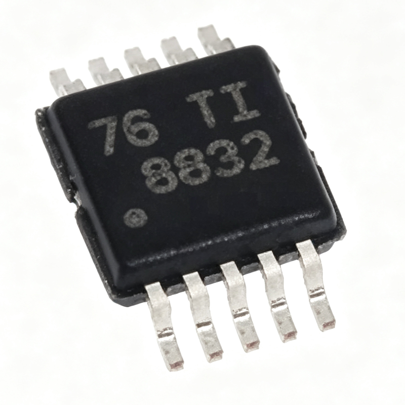
DRV8832DGQR - 1A H-Bridge Motor Driver 6.8V | Texas Instruments
The Texas Instruments DRV8832DGQR is a 1 A low-voltage H-bridge motor driver with integrated voltage regulation, operating from a 2.75 V to 6.8 V supply and housed in a 10-pin HVSSOP (DGQ) package with exposed thermal pad. An H-bridge motor driver is a power management IC that controls the direction and speed of a DC motor by selectively energizing four power transistors arranged in an H configuration. It sits between a low-power microcontroller and the motor winding, translating logic-level control signals into high-current drive. Within the semiconductor hierarchy, the DRV8832 belongs to the motor driver family under power management ICs, complementary to voltage regulators and gate drivers in motion-control signal chains. Key features include a high-efficiency power stage built from N-channel and P-channel power MOSFETs with low RDS(on), achieving up to 97% efficiency. The integrated voltage-regulation loop maintains a stable effective motor voltage, improving speed regulation directly from a discharging battery. A current-limit function regulates winding current during motor start-up or stall, and a dedicated nFAULT output pin signals fault conditions to a host processor. Technically, the DRV8832 provides one H-bridge controlled by IN1 and IN2 logic inputs, capable of driving one brushed DC motor, one winding of a stepper motor, or other loads such as solenoids. Protection includes thermal shutdown and undervoltage lockout (UVLO) for robust field operation. The tiny 3 mm x 3 mm package supports compact, battery-powered layouts, and the device is offered in eco-friendly RoHS-compliant construction without Sb/Br. Typical applications include battery-powered toys, printers, and other portable motion-control products, where its wide 2.75 V to 6.8 V supply range tracks battery discharge directly, plus small-appliance actuators and solenoid drivers. When designing with this device, provide adequate PCB copper under the exposed thermal pad for heat dissipation at sustained 1 A loads, and place decoupling capacitors close to the supply pins to minimize voltage transients during PWM switching. This page synthesizes distributor pricing context, verified drop-in alternatives, comparison data, and practical design notes not found in the manufacturer datasheet alone.

DRV8832DRCR - 6.8V 1A H-Bridge Motor Driver | Texas Instruments
The Texas Instruments DRV8832DRCR is a 6.8V, 1A H-bridge brushed DC motor driver IC with integrated current regulation, housed in a 3-mm x 3-mm 10-pin VSON (DRC) package. It integrates the power MOSFETs, gate drive, current-limit circuitry, and fault reporting needed to drive one brushed DC motor or one winding of a stepper motor from a single low-voltage supply. An H-bridge motor driver is a power management IC that uses four switching transistors arranged in an H configuration to reverse the polarity of the voltage applied to a motor, enabling forward, reverse, brake, and coast (hi-Z) operation. Within the system hierarchy, motor drivers sit between a host controller (MCU or logic) and the motor itself, translating low-current logic commands into high-current motor drive while providing protection features such as current limiting, undervoltage lockout, and thermal shutdown. Key features include a wide operating supply range for battery-powered designs, a fixed off-time PWM current-regulation scheme that limits motor current during start-up or stall conditions, a low-power sleep mode that reduces supply current to conserve battery life, and an nFAULT output pin that signals fault conditions to a host processor. The integrated MOSFETs deliver up to 1A of continuous output current without external discrete transistors. The DRV8832 architecture uses internal gate drive and voltage regulation so that only the motor supply and logic inputs are required externally - no external bootstrap components or gate-drive circuitry are needed. The internal current-limit regulation repeatedly disables and re-enables the bridge at a fixed off-time when the set current threshold is exceeded, holding motor torque under control during stall or acceleration events and protecting both the IC and the motor windings. Typical applications include battery-powered toys, printers, and other low-voltage or battery-powered motion control products such as small actuators, camera lenses, locks, and consumer robotics. The low minimum supply voltage suits single-cell or dual-cell battery stacks, and the tiny 3x3 mm footprint suits space-constrained mechanisms in printers and portable devices. A key design consideration is thermal management: at high load currents the VSON-10 package relies on its exposed pad soldered to a copper pour on the PCB to dissipate heat. Verify that the continuous motor current and the on-resistance of the internal MOSFETs keep junction temperature within limits over the full ambient range. This page synthesizes verified distributor data, TI product information, drop-in alternative analysis, and practical design notes not found in the manufacturer datasheet, providing an engineering-ready reference for the DRV8832DRCR.

DRV8873QPWPRQ1 - 40V 10A H-Bridge Motor Driver | TI
The Texas Instruments DRV8873QPWPRQ1 is an automotive-grade, 40V, 10A H-bridge motor driver with integrated current sensing, housed in a 24-pin HTSSOP (PWP) PowerPAD package. It operates from a single supply of 4.5V to 38V and is AEC-Q100 qualified for harsh automotive environments. A brushed DC motor driver is a power management IC that controls direction and speed of motors by switching four N-channel MOSFETs in an H-bridge configuration. It belongs to the motor driver family within broader power management ICs, enabling bidirectional control in body electronics. Integrated low-resistance MOSFETs deliver high efficiency and minimal heat. Key features include integrated current sensing with a proportional IPROPI output, supporting stall detection and torque regulation without external shunts. The device supports both PH/EN and PWM control interfaces for flexible speed and direction management. Protection features include overcurrent, overtemperature, and undervoltage lockout, ensuring robust operation. Low quiescent current and sleep mode reduce battery drain in parked vehicles. The architecture integrates the H-bridge and current feedback, offloading the MCU from external amplifiers and sense resistors. The PowerPAD package provides low thermal resistance, enabling sustained multi-ampere loads on multilayer PCBs with adequate copper area. This simplifies system design and reduces BOM cost. Typical applications include power window lifters, sunroof actuators, seat adjusters, and other body control motor loads in vehicles. The wide input range also supports 12V and 24V automotive systems. Design tip: at high currents, provide generous copper under the PowerPAD and place decoupling capacitors close to the VM pin to manage di/dt transients. This page synthesizes distributor pricing, drop-in alternatives, and practical design notes not found in the manufacturer datasheet.

DRV8876PWPT - 40V 3.5A H-Bridge Motor Driver | TI
The Texas Instruments DRV8876PWPT is a 40-V, 3.5-A H-bridge motor driver with integrated current sensing and current-sense feedback, designed for driving one bidirectional brushed DC motor or two unidirectional brushed DC motors. It operates from a 4.5-V to 37-V supply voltage range and is available in a 16-pin HTSSOP (PWP) package. The device integrates an N-channel H-bridge, charge pump regulator, current sensing and regulation, and protection features, making it a compact and efficient solution for a wide range of motor control applications. An H-bridge motor driver is a power management IC that controls the direction and speed of a brushed DC motor by selectively turning on four transistors in an H configuration. The DRV8876 integrates the H-bridge, gate drivers, and protection circuitry into a single package, simplifying PCB design and reducing component count. It is part of the DRV887x family of brushed DC motor drivers, which are known for their flexibility and robustness. Key features include a 4.5-V to 37-V operating supply voltage, 3.5-A peak drive current, integrated current sensing with adjustable current regulation, and a low-power sleep mode. The device also provides overcurrent, overtemperature, and undervoltage lockout protection. The integrated current sense amplifier outputs a voltage proportional to the motor current, enabling precise torque control without external sense resistors. The DRV8876 uses an N-channel H-bridge architecture with a charge pump to drive the high-side FETs, achieving low RDS(on) and high efficiency. The current regulation feature allows the motor current to be limited to a programmable level, protecting the motor and power supply. The device is designed for industrial and consumer applications, including printers, robotics, and home appliances. Typical applications include brushed DC motor control in printers, robotics, and industrial automation. The wide supply voltage range and integrated protection make it suitable for battery-powered and industrial systems. The HTSSOP package with exposed thermal pad aids in heat dissipation, enabling reliable operation at high currents. When designing with the DRV8876, ensure adequate PCB copper area for thermal management, and place the charge pump capacitor close to the CP1 and CP2 pins. The current sense resistor should be placed near the ISEN pin to minimize noise. Proper decoupling on the VM pin is essential for stable operation.

FSAM30SH60A - 600V 30A 3-Phase Motion SPM2 IPM | onsemi
The onsemi FSAM30SH60A is a Motion SPM 2 series Smart Power Module (SPM) integrating a complete three-phase IGBT inverter stage rated 600 V and 30 A in a 32-pin PowerDIP (SPM32-AA) module with 34.80 mm body width and 2500 Vrms isolation. A Smart Power Module is a type of intelligent power module (IPM) that combines power switches (IGBTs with integrated freewheeling diodes), their optimized gate drivers, and protection circuitry in a single compact, isolated package. Within the power electronics hierarchy, it sits above discrete IGBTs and gate-driver ICs, forming a complete power-management inverter subsystem for motor control. Key features include built-in under-voltage lockout (UVLO) on all three high-side and low-side channels, over-current protection (OCP) realized through advanced current-sensing IGBTs, and optimized gate-drive characteristics that minimize EMI and switching losses. These protections improve system reliability in inverter-driven motor applications. Technically, the module integrates HVIC-based gate drive with level-shifting for high-side channels, allowing a single positive 15 V supply without external bootstrap complexity on low-side rails, matched to low-loss IGBTs for efficient inverter operation in the fractional to low-horsepower range. Typical applications include washing machine motor drives, air conditioner compressor inverters, and AC induction, BLDC, and PMSM motor drives in low-power appliance and light industrial equipment. Design consideration: ensure bootstrap capacitor sizing and the sense-resistor value for OCP trip level are set per the manufacturer datasheet; excessive VCE(sat) rise from undersized heatsinking will degrade thermal margins. This page synthesizes distributor availability, cross-reference alternatives, and design guidance not consolidated in the manufacturer datasheet alone.
FSBS5CH60 - 600V 5A 3-Phase IGBT Motion SPM 3 Module | onsemi
The onsemi FSBS5CH60 is a Motion SPM 3 smart power module providing a fully-featured, high-performance inverter output stage for three-phase motor drives, rated 600 V and 5 A in a 27-pin PowerDIP module package with offset leads. A smart power module (SPM) is an integrated power assembly that combines a three-phase IGBT inverter bridge with optimized gate-drive circuitry, protection functions, and often bootstrap diodes in a single compact package. Within the power-electronics hierarchy, the SPM sits between discrete IGBT-plus-driver solutions and full intelligent power modules (IPMs), consolidating the power stage and control interface into one surface-mountable footprint. This reduces PCB area, parasitic inductance, and assembly complexity for low-power AC motor inverter designs. Key features include a 600 V breakdown rating suitable for rectified 220-240 V AC mains, a 5 A collector-current rating, integrated high-side gate drivers with under-voltage lock-out (UVLO), and built-in over-current protection. According to onsemi product documentation, the module integrates optimized gate drive matched to low-loss IGBTs to minimize EMI and switching losses, enhancing overall system reliability. The internal architecture pairs each IGBT with a freewheeling diode and dedicated gate-drive circuitry. Level-shifting circuitry enables high-side control from a common logic input, while the matched driver/IGBT combination yields controlled switching speeds that reduce dv/dt-induced EMI in appliance environments. Typical applications include low-power AC induction, BLDC, and PMSM motor drives in air conditioners, washing machines, and refrigeration compressors, where the 600 V rating covers single-phase mains-fed inverters. Design consideration: verify the current rating against motor stall current, and ensure bootstrap capacitor sizing supports the minimum PWM switching frequency without high-side UVLO trips. This page synthesizes distributor pricing, availability, drop-in alternatives, and practical design notes not found in the manufacturer datasheet.

IFX007TAUMA1 - 40A Half-Bridge Motor Driver | Infineon NovalithIC
The Infineon IFX007TAUMA1 is an integrated high-current half-bridge motor driver from Infineon's Industrial & Multi-Purpose NovalithIC™ family, featuring one p-channel high-side MOSFET and one n-channel low-side MOSFET with an integrated driver IC in a single PG-TO263-7-1 (D2PAK-7) surface-mount package. The device delivers up to 40 A continuous load current, has a typical MOSFET RDS(on) of 12.8 mΩ, and operates over a 5.5 V to 40 V supply range suitable for automotive and industrial motor drive applications. A half-bridge (H-bridge half) driver is a power-management IC that combines one low-side and one high-side power MOSFET with their gate-drive circuitry on a single die, enabling bidirectional current control through a load (such as a motor winding) using only two external logic-level control signals. The half-bridge belongs to the broader category of full, half-bridge (H-bridge) drivers within PMIC (Power Management IC) products, which sit above discrete MOSFET driver + power MOSFET designs in the power-electronics hierarchy and below fully integrated motor-driver SoCs that include microcontrollers or predrivers. Key features include 5.5 V to 40 V operating voltage, 12.8 mΩ typical RDS(on) per MOSFET, integrated charge pump for the high-side gate drive, logic-level inputs (IN = 1.6 V to 2 V high / 1.1 V to 1.3 V low), PWM capability up to 25 kHz, status flag output, and protection functions including over-temperature shutdown, over-current latch, under-voltage lockout, and short-circuit detection. The PG-TO263-7-1 package exposes the tab as the power ground/drain thermal pad, providing a low thermal resistance path suitable for continuous high-current operation. Internally the IFX007T uses Infineon's proprietary smart power technology combining vertical p-channel high-side and vertical n-channel low-side MOSFETs with a CMOS/BCD control section on the same silicon. This monolithic integration eliminates the parasitic inductance and gate-loop inductance found in discrete half-bridge designs, dramatically reducing switching losses, ringing, and EMI. The integrated charge pump generates the high-side gate-drive voltage rail from the logic supply, allowing true 100 % duty-cycle operation and low-side freewheeling. Current sensing is performed by monitoring the low-side MOSFET RDS(on), eliminating an external shunt resistor. Typical applications include DC motor control (brushed DC and BLDC with external commutation), solenoid and valve drivers, industrial automation actuators, automotive body and powertrain actuators, and battery-powered tools. When designing with this part, ensure adequate copper area on the exposed tab for thermal dissipation - at 30 A continuous the package can dissipate several watts - and follow Infineon's PCB layout guidelines to keep the bootstrap capacitor loop short for reliable high-side switching. This page synthesizes distributor pricing across 7 sources, drop-in same-package alternatives, and practical design notes not collected in the manufacturer datasheet, including thermal budgeting and pin-compatibility verification.
IFX9201SGAUMA1 - 6A H-Bridge DC Motor Driver | Infineon | 5-36V
The Infineon IFX9201SGAUMA1 is a 6 A general-purpose H-bridge motor driver designed for DC motor control, housed in a 12-pin PG-DSO-12-17 (DSO Exposed Pad) surface-mount package. It operates from 5 V to 36 V supply, integrates two power MOSFET half-bridges, and supports PWM/DIR control with SPI diagnostics, making it suitable for industrial, building-automation, power-tool, and battery-management applications. The exposed thermal pad reduces junction-to-ambient thermal resistance for sustained high-current operation up to 6 A continuous. An H-bridge motor driver is an integrated power stage built from four switching elements (two high-side and two low-side MOSFETs) arranged in an "H" topology, allowing bidirectional current flow through a DC motor or inductive load. The bridge sits in the broader motor-driver hierarchy between simple logic-level MOSFET half-bridges and fully-isolated three-phase inverter modules used for AC servo drives. Compared with discrete MOSFET implementations, an integrated H-bridge like the IFX9201SG reduces PCB footprint, simplifies fault handling, and provides matched dead-time control across the high-side and low-side switches. Key features of the IFX9201SGAUMA1 include integrated charge-pump gate drive for 100% duty-cycle operation, programmable current limit, adjustable slew rate via gate-resistor selection, undervoltage lockout, overcurrent shutdown, and overtemperature protection. The SPI interface exposes diagnostic registers for short-circuit, open-load, and thermal-warning flags, enabling predictive maintenance in industrial fieldbus nodes. The device accepts logic-level 3.3 V or 5 V PWM and direction inputs, allowing direct connection to a microcontroller GPIO without level shifters. The internal architecture uses N-channel MOSFETs on both high-side and low-side positions to minimize RDS(on), driven by an internal charge pump that maintains gate enhancement at low supply voltages. PWM chopping up to 25 kHz is supported for current control or average-voltage regulation, while the SPI block runs up to 4 MHz for fast fault readback. Typical applications include small brushed-DC motor drives in power tools, home-appliance pumps and valves, building-automation dampers, medical pumps, and battery-management relay drivers. The wide 5 V to 36 V input range covers both 12 V lead-acid and 24 V industrial bus rails. When designing with this part, place the supply and motor-side bypass capacitors close to the IC and tie the exposed pad to a sufficiently large copper pour to keep junction temperature within ratings at full 6 A continuous current. Use the SPI diagnostics to flag fault conditions to the host MCU rather than relying on software polling of external sense resistors. This page synthesizes distributor pricing, drop-in alternatives, and practical design notes not found in the Infineon datasheet.

IKCM30F60GAXKMA1 - 600V 30A CIPOS Mini IPM | Infineon
The Infineon IKCM30F60GAXKMA1 is a CIPOS Mini intelligent power module (IPM) integrating a three-phase 600 V, 30 A TRENCHSTOP IGBT inverter stage with open emitter, gate drivers, bootstrap diodes, and protection logic in a single 24-pin PowerDIP module (36x21 mm). It delivers up to 30 A of phase current at 600 V blocking voltage, optimized for compact motor drives below 4 kW. An intelligent power module (IPM) is a high-level integration device that combines the power semiconductor switching devices (IGBTs or MOSFETs), their gate drivers, and protection features such as short-circuit, under-voltage, and over-temperature in one isolated package. IPMs sit at the top of the power-management hierarchy: power switch -> IGBT module -> intelligent power module -> motor inverter subsystem. By eliminating discrete driver/layout design, they accelerate time-to-market for variable-frequency drives (VFDs). Key features of the IKCM30F60GAXKMA1 include: 600 V collector-emitter breakdown voltage, 30 A nominal phase current, integrated bootstrap diodes for the high-side drivers, open-emitter outputs for individual phase current sensing, an integrated thermistor for over-temperature shutdown, and short-circuit/under-voltage lockout protection. The TRENCHSTOP IGBT technology minimizes VCE(sat) and switching losses simultaneously, raising inverter efficiency into the 96-98% range at typical switching frequencies of 4-16 kHz. The module uses a 36x21 mm DIP-style lead-form package with 4 mm of creepage/clearance between the power and signal sides, providing electrical isolation rated above 2 kVrms. The exposed DBC substrate enables direct cooling via a heat plate, supporting sustained 30 A operation without derating up to roughly 80 C ambient. The CIPOS Mini family is pin-compatible with prior generations, allowing direct PCB upgrades in existing designs. Typical applications include variable-frequency drives for washing machines, refrigerator compressors, fan and pump motors, and small industrial drives (typically 0.4-2.2 kW). It is also used in three-phase solar micro-inverters, HVAC blowers, and small servo drives where space is constrained and reliability is critical. When designing with this IPM, ensure the bootstrap capacitors (typically 1 uF per high side) are sized correctly for the switching frequency and duty cycle. Place a 100 nF + electrolytic bulk capacitor on the +15 V supply to suppress gate-driver noise, and keep the analog ground (signal side) star-connected to the power ground at a single point near the DC-link negative terminal to avoid ground-loop-induced false tripping.

IR2130SPBF - 3-Phase Bridge Driver, 600V, 28-SOIC | Infineon
The Infineon IR2130SPBF is a high-voltage, high-speed 3-phase bridge gate driver IC delivering 500 mA source/sink drive current for power MOSFETs and IGBTs, housed in a 28-pin SOIC package. It integrates three independent high-side and three low-side referenced output channels, proprietary HVIC technology, and a ground-referenced operational amplifier for analog feedback of bridge current. A gate driver is a power-management integrated circuit that sits between a low-power control MCU/DSP and the high-current gate of a power switch (MOSFET or IGBT). It provides level shifting, voltage translation, and current amplification so a 3.3 V or 5 V logic signal can efficiently switch a 600 V half-bridge. The IR2130SPBF belongs to the half-bridge / 3-phase driver family within power management ICs (HVIC -> gate driver -> motor driver -> power management IC). This category enables compact, reliable inverters by eliminating the optocouplers and discrete bootstrap networks that older designs required. Key features of the IR2130SPBF include 600 V maximum offset voltage on the high-side channels, 10 V to 20 V supply range, CMOS/LSTTL-compatible logic inputs down to 2.5 V, integrated deadtime control, and over-current protection with fault reporting via the FAULT and RCIN pins. The integrated current-sense op-amp removes the need for an external amplifier in most motor-drive feedback loops. Under-voltage lockout (UVLO) for both VCC and VBS protects the power switches from insufficient gate-drive voltage. Architecturally, the IR2130SPBF uses Infineon's proprietary HVIC process to integrate level-shifting high-side drivers with low-side drivers on a single die, supporting switching frequencies up to several hundred kHz. Propagation delays are tightly matched between channels (~425 ns typical per the datasheet overview), which is essential for 3-phase PWM to avoid circulating currents and torque ripple. Typical applications include 3-phase variable-frequency drives (VFDs) for AC induction motors, brushless DC (BLDC) and permanent-magnet synchronous motor (PMSM) controllers, industrial servo amplifiers, uninterruptible power supplies (UPS), and appliance motor control. The wide supply range and integrated fault protection also suit solar micro-inverters and small EV traction auxiliaries. When designing with the IR2130SPBF, careful attention to bootstrap capacitor selection and PCB layout is critical - high-side channels float with the phase output, so the dV/dt immunity and the bootstrap refresh interval determine long-term reliability. Avoid routing the FAULT/RCIN traces near switching nodes to prevent false tripping. This page synthesizes distributor pricing, drop-in alternatives, and practical design notes not found in the manufacturer datasheet, giving engineers an actionable selection reference for 3-phase motor-drive designs.
IRSM808-105MH - 10A 500V Half-Bridge IPM | Infineon
The Infineon IRSM808-105MH is a 10 A, 500 V half-bridge Intelligent Power Module (IPM) integrating two 500 V Trench FREDFET power MOSFETs with a rugged HVIC gate driver in a single isolated PQFN 8x9 mm package. The half-bridge delivers up to 200 W of switching power for appliance motor drive applications, with a maximum RDS(on) of 0.8 ohm per switch, enabling energy-efficient operation without an external heatsink in most small-appliance designs. An Intelligent Power Module (IPM) is a fully integrated power-electronics building block that combines the power stage (typically IGBT or MOSFET switches) and the gate-driver circuitry into a single, electrically isolated package. IPMs sit within the broader power-semiconductor taxonomy: power module -> IPM -> half-bridge module -> motor-driver IPM. By co-packaging the gate driver with the power switches, IPMs reduce parasitic inductance, shrink PCB area, shorten design cycles, and provide built-in protection that would otherwise require dozens of discrete components. Key features of the IRSM808-105MH include 500 V blocking voltage per switch, 0.8 ohm maximum RDS(on), a built-in dead-time generation block, an enable/FAULT interface, and under-voltage lockout (UVLO) on the bootstrap supply. The module integrates two 500 V FREDFETs in a half-bridge topology, allowing designers to construct single-phase or three-phase inverter stages by combining two or three modules with a small microcontroller. The PQFN 8x9 mm footprint offers up to 60% smaller PCB area than discrete 3-phase inverter solutions. Typical applications include energy-efficient fan and pump motor drives, refrigerator compressor inverters, washing-machine drain-pump drives, dishwasher circulation pumps, and small HVAC blowers. The integrated dead-time control simplifies firmware, while the high 500 V rating provides ample margin across universal-input 110/220 Vac rectified DC-bus designs. The rugged HVIC tolerates negative VS transients and provides ESD-protected logic inputs, increasing field reliability compared with discrete gate-driver approaches.

IRSM808-105MHTR - 10A 500V Half-Bridge IPM | Infineon
The Infineon IRSM808-105MHTR is a 10 A, 500 V half-bridge Intelligent Power Module (IPM) housed in a 31-pin PQFN (8x9 mm) surface-mount package with an electrically isolated thermal pad. It integrates two Trench FREDFET power MOSFETs in a half-bridge topology together with a dedicated high-voltage gate driver IC, targeting advanced appliance motor drive applications such as energy-efficient fans and pumps. According to the Infineon datasheet, the module operates from a 13.5 V to 16.5 V logic supply and is rated for 200 W of continuous motor drive power. An Intelligent Power Module (IPM) is an integrated power-electronics building block that combines the power semiconductor switches (typically IGBTs or power MOSFETs), their gate drivers, and protection features (short-circuit, under-voltage, over-temperature) into a single isolated package. IPMs sit hierarchically between discrete MOSFET/IGBT half-bridges (lower integration) and full motor-control SoCs (higher integration), giving designers a compact, drop-in power stage for variable-frequency drives. The IRSM808-105MHTR leverages Infineon's low-RDS(on) Trench FREDFET process to minimize conduction losses in the 500 V power stage. Key specifications include a 500 V drain-source blocking voltage, 10 A continuous output current, integrated bootstrap diode for the high-side supply, and built-in over-current and thermal shutdown protection. The exposed top-side thermal pad provides a direct thermal path to the PCB copper or an optional heatsink, enabling compact designs without bulky external cooling hardware. Logic-level inputs accept 3.3 V or 5 V CMOS signals, simplifying interface to microcontrollers such as the XMC1000 or XMC4000 series. The architecture uses Infineon's benchmark high-voltage level-shift and bootstrap gate-drive technology to control the high-side switch without requiring an isolated DC/DC converter. This reduces BOM count and PCB area while improving reliability. The integrated dead-time generation prevents cross-conduction of the low-side and high-side MOSFETs, a common failure mode in discrete half-bridge designs. Typical applications include energy-efficient ceiling fans, refrigerator compressors, dishwasher circulation pumps, and small HVAC blowers - any appliance that benefits from variable-speed brushless DC or PMSM motor control. The 200 W rating covers most sub-1 HP residential appliance motors. When designing with this IPM, place low-ESR ceramic bypass capacitors directly on the VCC and V+ pins to handle the gate-charge current spikes during switching. Ensure the exposed thermal pad has at least 1 square inch of copper pour and thermal vias to a second-layer inner plane for rated 10 A continuous operation. This page synthesizes distributor pricing, drop-in alternatives, and practical PCB layout notes not found in the manufacturer datasheet summary.
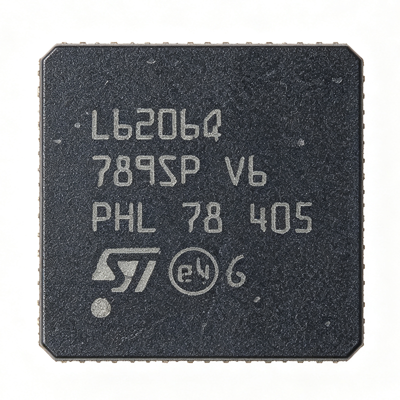
L6206Q - Dual DMOS Full-Bridge Driver 8A | STMicroelectronics
The STMicroelectronics L6206Q is a dual DMOS full-bridge motor driver capable of delivering up to 2.8A per channel (8A peak total) in a 48-pin QFN (QFN48) package. It operates from a supply voltage range of 8V to 52V, making it suitable for a wide variety of industrial and automotive motor control applications. The device integrates two independent H-bridges with a total output current of 5.6A continuous (2.8A per bridge), and includes thermal shutdown and undervoltage lockout protection. A DMOS full-bridge driver is a type of power integrated circuit that uses four N-channel DMOS transistors arranged in an H-bridge configuration to control the direction and speed of a DC motor or the phase currents of a stepper motor. It belongs to the broader category of motor drivers, which are power management ICs that translate low-power control signals into high-current, high-voltage outputs. The L6206Q sits in the hierarchy: DMOS full-bridge driver -> motor driver -> power management IC -> semiconductor. Key features include a low RDS(on) of 0.3 ohm per switch, which minimizes power dissipation and improves efficiency, and a fast switching frequency of up to 100 kHz, enabling precise PWM control. The device also features a non-dissipative overcurrent protection (OCP) that limits the output current to a safe level, and a diagnostic output that indicates fault conditions. The QFN48 package provides a compact footprint with an exposed thermal pad for enhanced heat dissipation. The L6206Q uses a mixed-signal BCD (Bipolar-CMOS-DMOS) process technology, integrating the DMOS power stage with CMOS control logic and bipolar protection circuits. This architecture allows for high current handling with low quiescent current and robust protection features. The device supports both parallel and bridge configurations, enabling flexible motor drive topologies. Typical applications include bipolar stepper motor drivers, DC motor drivers for robotics and automation, and brushless DC motor pre-drivers. The wide supply voltage range and high current capability make it ideal for industrial automation, CNC machines, and automotive actuators. In a stepper motor application, the L6206Q can drive two-phase motors with up to 2.8A per phase, providing smooth microstepping control. When designing with this device, ensure adequate PCB copper area for the thermal pad to dissipate heat, especially at high output currents. The VREF pin allows current sensing and regulation, which is essential for torque control in stepper applications. The EN pins provide independent enable control for each bridge, enabling power-saving modes. This page synthesizes distributor pricing, drop-in alternatives, and practical design notes not found in the ST datasheet, providing a comprehensive resource for engineers selecting a dual full-bridge driver.
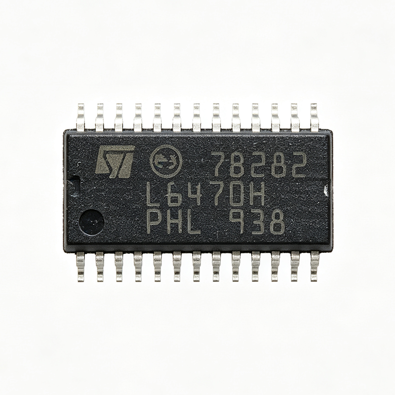
L6470H - dSPIN Stepper Motor Driver | STMicroelectronics | HTSSOP-28
The STMicroelectronics L6470H is a fully integrated microstepping motor driver with an embedded dSPIN™ motion engine, delivering up to 3 A peak output current per phase in a 28-pin HTSSOP (PowerSO-28) package. It operates from a supply voltage range of 8 V to 45 V and features programmable microstepping up to 1/128 step, making it suitable for high-resolution motion control applications. Data verified as of 2026-08-05. A stepper motor driver is a power management IC that translates digital step and direction commands into the precise current sequences needed to rotate a bipolar stepper motor. The L6470H belongs to the motor driver category, which sits within the broader power management IC hierarchy: motor driver -> power management IC -> semiconductor. Its integrated motion engine offloads complex acceleration and deceleration profiles from the host microcontroller, enabling smoother motion and reduced processor load. Key features include a programmable motor current from 0 mA to 3 A RMS, SPI interface for configuration and control, and a wide range of protection features such as overcurrent, overtemperature, and undervoltage lockout. The device also integrates a 1/128 microstepping capability, which significantly reduces motor noise and vibration compared to full-step operation. The HTSSOP-28 package with exposed pad provides excellent thermal performance, with a thermal resistance of 25 °C/W, enabling operation at high currents without external heatsinking in many applications. The L6470H uses a proprietary dSPIN™ architecture that combines a power stage, current sensing, and a motion profile generator on a single die. This integration reduces external component count and simplifies PCB layout. The SPI interface allows real-time adjustment of motor parameters, such as acceleration, deceleration, and target speed, enabling adaptive motion control in dynamic systems. The device also supports daisy-chaining of multiple drivers on a single SPI bus, simplifying multi-axis systems. Typical applications include 3D printers, CNC machines, robotics, and automated textile machinery. In a 3D printer, the L6470H's high microstepping resolution and quiet operation are critical for achieving precise layer deposition and reducing print artifacts. In robotics, the integrated motion engine allows smooth, controlled movement of joints and actuators, improving overall system performance. When designing with the L6470H, ensure adequate supply decoupling with a 100 nF ceramic capacitor close to the VSA and VSB pins, and a bulk capacitor (≥10 µF) on the supply rail. The exposed pad must be soldered to a large copper area for thermal management. The SPI lines should be kept short and shielded to avoid noise coupling into the motor current sense circuitry. This page synthesizes distributor pricing, drop-in alternatives, and practical design notes not found in the ST datasheet, providing engineers with a comprehensive resource for evaluating the L6470H in their motion control designs.

L6470HTR - dSPIN Stepper Motor Driver | STMicroelectronics
The L6470HTR is a fully integrated microstepping motor driver from STMicroelectronics, part of the dSPIN family. It combines a complete motor control system on a single chip, including a power stage with dual full-bridge drivers, a digital control core, and a serial interface. The device is designed to drive bipolar stepper motors with up to 3 A peak current per phase, operating from a supply voltage range of 8 V to 45 V. It is available in a compact HTSSOP28 package, making it suitable for space-constrained applications. A stepper motor driver is a power management IC that translates digital step and direction commands into the precise current sequences needed to rotate a stepper motor. The L6470HTR integrates the control logic, gate drivers, and power MOSFETs, eliminating the need for external components and simplifying PCB design. It belongs to the hierarchy: stepper motor driver -> motor driver -> power management IC -> semiconductor. This integration reduces system cost and board space while improving reliability. Key features of the L6470HTR include programmable microstepping up to 1/128 step, which provides smooth motion and high positioning accuracy. It offers a wide range of protection features, including overcurrent, overtemperature, and undervoltage lockout. The device also includes a SPI interface for configuration and control, allowing real-time adjustment of motor parameters. The integrated current sensing eliminates the need for external sense resistors, further reducing component count. The L6470HTR uses a proprietary control algorithm that automatically adjusts the current decay mode to optimize performance across different motor types and load conditions. This adaptive decay control minimizes audible noise and power dissipation. The device also features a programmable slew rate to reduce electromagnetic interference (EMI) in sensitive applications. The digital core operates at up to 16 MHz SPI clock, enabling fast communication with microcontrollers. Typical applications include 3D printers, CNC machines, robotics, office automation, and industrial automation. In 3D printers, the L6470HTR provides precise filament positioning with microstepping, resulting in high-quality prints. In CNC machines, it drives stepper motors for axis movement with high torque and accuracy. The device's wide voltage range and current capability make it versatile for various motor sizes. When designing with the L6470HTR, ensure proper thermal management by providing adequate copper area on the PCB for heat dissipation. The HTSSOP28 package has an exposed pad that must be soldered to a thermal relief. Additionally, place decoupling capacitors close to the power supply pins to minimize voltage transients. The SPI interface allows configuration of motor parameters, but careful attention to the register settings is required to avoid unintended behavior.
L6480H - 10A Dual Full-Bridge Stepper Motor Driver | STMicroelectronics
The STMicroelectronics L6480H is a fully integrated dual full-bridge stepper motor driver capable of delivering up to 10A peak output current per bridge, designed for high-performance motion control applications. It operates from a supply voltage range of 8V to 85V and integrates a complete digital control core with SPI interface, making it a versatile solution for industrial automation, robotics, and CNC machinery. The device is housed in a 28-pin HTSSOP (H) package with an exposed thermal pad, enabling efficient heat dissipation in compact designs. Data verified as of 2026-08-05. A stepper motor driver is a power management IC that translates digital step and direction commands into precise current-controlled pulses for driving bipolar stepper motors. It sits within the hierarchy: stepper motor driver -> motor driver -> power management IC -> semiconductor. The L6480H integrates both the power stage and the control logic, eliminating the need for external MOSFETs and simplifying PCB design. This integration reduces component count and improves reliability, making it a key building block in modern motion control systems. Key features of the L6480H include a programmable output current up to 10A peak, microstepping up to 1/128 step, and a wide supply voltage range of 8V to 85V. It also features overcurrent, overtemperature, and undervoltage protection, ensuring robust operation in harsh industrial environments. The SPI interface allows real-time configuration and monitoring, while the dedicated STEP and DIR pins enable simple interfacing with microcontrollers or motion controllers. The L6480H utilizes a proprietary advanced current control algorithm that minimizes motor noise and vibration, improving positioning accuracy. The device supports both full-step and microstepping modes, with the ability to adjust the decay mode for optimal performance across different motor types. The integrated sense resistors eliminate the need for external current sensing, further reducing BOM cost and board space. Typical applications include CNC machines, 3D printers, textile machinery, and automated assembly equipment. The L6480H's high current capability and wide voltage range make it suitable for driving large NEMA 34 and NEMA 42 stepper motors, which are common in industrial automation. Its SPI interface also enables advanced features like stall detection and position tracking, enhancing system intelligence. When designing with the L6480H, ensure adequate PCB copper area for thermal dissipation, as the device can dissipate significant power at high currents. The exposed pad must be soldered to a thermal via array connected to a ground plane. Additionally, place decoupling capacitors close to the VM and VCC pins to minimize voltage transients. This page synthesizes distributor pricing, drop-in alternatives, and practical design notes not found in the STMicroelectronics datasheet, providing engineers with a comprehensive resource for selecting and implementing the L6480H in their designs.
L9369 - Automotive H-Bridge Gate Driver | STMicroelectronics
The L9369 is a highly integrated automotive H-bridge gate driver IC from STMicroelectronics, designed for driving external N-channel MOSFETs in DC motor control and solenoid actuation applications. It operates from a supply voltage range of 5.5V to 40V and provides two half-bridge outputs capable of driving high-side and low-side MOSFETs with programmable gate drive currents. The device integrates a serial peripheral interface (SPI) for configuration and diagnostics, making it suitable for advanced automotive body control modules. An H-bridge gate driver is a power management IC that controls the gates of four external MOSFETs arranged in an H-bridge topology, enabling bidirectional current flow through a load such as a DC motor. It translates low-voltage logic signals into high-current gate drive pulses, providing the necessary voltage and current to switch the MOSFETs efficiently. In the system hierarchy, the L9369 sits between the microcontroller (MCU) and the power stage, acting as an interface that offloads high-current switching tasks from the MCU while adding protection and diagnostic features. Key features of the L9369 include a wide operating voltage range, programmable gate drive current for optimized switching performance, and comprehensive diagnostic functions via SPI. The device supports both high-side and low-side MOSFET drivers with adaptive dead-time control to prevent shoot-through currents. It also includes overcurrent, overtemperature, and undervoltage lockout protections, enhancing system reliability in harsh automotive environments. From a technical architecture perspective, the L9369 integrates charge pumps for high-side gate drive, level shifters for high-voltage domains, and a SPI-compatible interface for register-based control. The device is fabricated using STMicroelectronics' BCD (Bipolar-CMOS-DMOS) technology, which combines low-power logic with high-voltage power handling. This allows the L9369 to operate directly from automotive battery voltages while maintaining low quiescent current in standby mode. Typical applications include automotive DC motor control for window lifts, sunroofs, and seat adjustment, as well as solenoid actuation for transmission control and fuel injection systems. The L9369's robust protection features and SPI diagnostics make it ideal for safety-critical systems where fault detection and reporting are essential. When designing with the L9369, ensure proper PCB layout with adequate copper area for thermal dissipation, and place decoupling capacitors close to the supply pins. The SPI interface should be isolated from high-current traces to minimize noise coupling. Additionally, the gate drive current settings must be matched to the external MOSFETs' gate charge to achieve optimal switching performance and minimize EMI.

L9369-TR - Automotive H-Bridge Driver for Electric Parking Brake | STMicroelectronics
The L9369-TR is an automotive-grade H-bridge driver IC from STMicroelectronics, specifically designed for electric parking braking (EPB) systems. It integrates two H-bridge driver stages to drive 8 external FETs for rear wheel brake actuators, supporting both cable-puller and Motor Gear Unit (MGU) configurations. The device is housed in a 64-pin LQFP (10x10 mm) package and operates from a supply voltage range of 5.5 V to 28 V, with a peak output current of 8.5 A per H-bridge. An H-bridge driver is a power management IC that controls the direction and speed of a DC motor by selectively turning on four transistors in an H-shaped configuration. It is a type of motor driver, which falls under the broader category of power management ICs. The L9369-TR is specifically designed for automotive applications, meeting the stringent AEC-Q100 qualification standard for reliability in harsh environments. Key features of the L9369-TR include a low RDS(on) of 0.15 ohm per switch, which minimizes power dissipation and improves efficiency. It also features a built-in current sense amplifier for precise motor current monitoring, and a SPI interface for advanced diagnostics and control. The device includes comprehensive protection features such as overcurrent, overtemperature, and undervoltage lockout, ensuring robust operation in automotive systems. The L9369-TR utilizes a smart power technology that integrates the power stage with control logic and protection circuits on a single die. This integration reduces external component count and improves system reliability. The SPI interface allows for real-time monitoring of fault conditions and precise control of the motor, making it suitable for advanced driver assistance systems (ADAS) and body control modules. Typical applications include electric parking brakes, electric power steering (EPS), electronic stability control (ESC), and active suspension systems. The device is also used in HVAC blower motors, cooling fan control, and window lift modules. Its high current capability and robust protection make it ideal for driving brushed DC motors in automotive environments. When designing with the L9369-TR, it is essential to ensure proper PCB layout with adequate copper area for heat dissipation. The 64-LQFP package has a thermal resistance of 25 C/W, so a heatsink or large copper pour is recommended for continuous high-current operation. Additionally, the SPI interface should be configured correctly to enable fault reporting and diagnostic functions.
L9370 - Automotive Electric Parking Brake IC | STMicroelectronics
The L9370 from STMicroelectronics is a specialized automotive IC designed for electric parking braking (EPB) systems, supporting both cable-puller and Motor Gear Unit (MGU) configurations. It integrates two H-bridge driver stages to drive eight external FETs for rear wheel brake actuators, enabling precise and reliable parking brake control. The device is housed in a 64-pin TQFP (10x10 mm) package, suitable for surface-mount assembly in automotive electronic control units (ECUs). An electric parking brake (EPB) is an automated parking brake system that replaces the traditional mechanical handbrake with electronic controls. The L9370 is a motor driver IC that sits between the vehicle's microcontroller and the brake actuator motors, providing the high-current H-bridge switching needed to drive the motors in both directions. In the broader system hierarchy, the L9370 is a specialized motor driver within the automotive power management and actuation domain, working alongside microcontrollers, power supplies, and sensor interfaces to deliver safe and reliable parking brake operation. Key features of the L9370 include dual H-bridge driver stages capable of driving eight external FETs, enabling bidirectional motor control for brake apply and release. The device is designed for automotive environments, with support for VDA 3.0 compliance (as noted in ST community discussions), ensuring compatibility with industry-standard safety and communication protocols. The 64-pin TQFP package offers a compact footprint while providing adequate thermal performance for automotive under-hood or in-cabin mounting. Technically, the L9370 integrates gate driver circuitry for the external FETs, with the gate driver block being identical to that of the L9369, another ST automotive IC. This design reuse ensures proven performance and simplifies qualification. The device operates over an extended automotive temperature range, typically -40°C to +125°C, and is designed to meet stringent automotive reliability standards, including AEC-Q100 qualification (though this should be verified from the datasheet). Typical applications include electric parking brake systems in passenger cars and light commercial vehicles, where the L9370 drives the brake actuator motors in cable-puller or MGU configurations. It is also suitable for other automotive actuation applications requiring dual H-bridge motor control, such as electronic stability control (ESC) or adaptive cruise control (ACC) actuators. When designing with the L9370, ensure proper thermal management by providing adequate copper area on the PCB for heat dissipation, especially when driving high-current motors. Also, implement robust EMI filtering on the motor supply lines to prevent interference with other vehicle electronics. The device requires careful layout of the high-current paths to minimize parasitic inductance and ensure reliable switching.
L9390 - 12-Channel Valve Driver | STMicroelectronics | Automotive
The STMicroelectronics L9390 is a specialized 12-channel valve driver integrated circuit designed for automotive and industrial actuation systems. Housed in a 100-pin eTQFP (14x14 mm) package, this device integrates high-current low-side drivers with advanced diagnostic and protection features, making it suitable for driving solenoid valves, injectors, and other inductive loads in engine management and transmission control units. A valve driver is a power management IC that translates low-power logic signals from a microcontroller into high-current, high-voltage drive signals capable of actuating electromechanical valves. In the system hierarchy, the L9390 sits between the engine control unit (ECU) microcontroller and the physical valves, functioning as a power actuator interface. This category of components is essential in automotive electronics, where reliable, high-current switching with built-in diagnostics is critical for safety and performance. Key features of the L9390 include 12 independent output channels, each capable of driving inductive loads with integrated freewheeling protection. The device supports a wide operating voltage range suitable for 12V and 24V automotive systems, and includes overcurrent, overtemperature, and open-load detection for each channel. The 100-pin eTQFP package provides excellent thermal performance and allows for compact PCB layouts in space-constrained engine control modules. The L9390 utilizes a robust BCD (Bipolar-CMOS-DMOS) process technology, enabling high-voltage operation with low quiescent current. Each output channel features a DMOS power transistor with low on-resistance, minimizing power dissipation and heat generation. The device includes a serial peripheral interface (SPI) for configuration and diagnostic readback, allowing the ECU to monitor valve health in real time and implement predictive maintenance strategies. Typical applications include diesel and gasoline engine management systems, where the L9390 drives fuel injectors and EGR valves, and automatic transmission control units, where it actuates hydraulic solenoids for gear selection. The device is also used in industrial automation for controlling pneumatic and hydraulic valves, and in commercial vehicle systems for managing air suspension and braking actuators. When designing with the L9390, ensure adequate PCB copper area for thermal dissipation, especially when driving multiple channels at high current simultaneously. The SPI interface should be properly configured for the desired diagnostic thresholds, and external flyback diodes or the integrated freewheeling protection should be verified against the specific inductive load characteristics to prevent voltage spikes.

L9904 - Automotive 3-Phase Brushless DC Motor Driver | STMicroelectronics
The STMicroelectronics L9904 is a highly integrated 3-phase brushless DC (BLDC) motor driver designed for automotive applications. It integrates a triple half-bridge gate driver, charge pump, and protection features in a 48-pin LQFP package. The device operates from a supply voltage range of 5.5V to 40V, making it suitable for 12V and 24V automotive electrical systems. It provides up to 1A gate drive current per channel, enabling efficient driving of external N-channel MOSFETs. A brushless DC motor driver is a power management IC that controls the commutation of a BLDC motor by sequentially energizing the motor windings. It typically includes gate drivers for the power stage, current sensing, and protection features. In the system hierarchy, a BLDC motor driver sits between the microcontroller (MCU) and the power MOSFETs, translating low-voltage logic signals into high-current gate drive signals. This component is essential in automotive applications such as electric power steering, engine cooling fans, and oil pumps, where precise motor control and reliability are critical. Key features of the L9904 include a programmable gate drive current, a built-in charge pump for high-side gate drive, and comprehensive protection features such as overcurrent, overvoltage, and thermal shutdown. The device also includes a SPI interface for configuration and diagnostics, allowing the MCU to monitor and control the motor driver in real time. The LQFP-48 package provides a compact footprint while maintaining good thermal performance, with a thermal resistance of 40°C/W. The L9904 utilizes a smart power technology that integrates analog and digital circuitry on a single chip. The charge pump enables 100% duty cycle operation of the high-side MOSFETs, which is crucial for high-speed motor applications. The SPI interface supports daisy-chaining of multiple devices, simplifying PCB layout in multi-motor systems. The device is AEC-Q100 qualified, ensuring reliability in harsh automotive environments. Typical applications include electric power steering (EPS), engine cooling fans, fuel pumps, and other automotive BLDC motor control systems. The wide supply voltage range and robust protection features make it ideal for 12V and 24V automotive electrical systems. The SPI interface allows for advanced motor control algorithms, such as field-oriented control (FOC), to be implemented by the MCU. When designing with the L9904, ensure proper PCB layout to minimize parasitic inductance in the gate drive loops. Use appropriate gate resistors to control switching speed and reduce EMI. The device requires a bootstrap capacitor for the high-side gate drive, which should be placed close to the IC pins. Thermal management is critical; ensure adequate copper area on the PCB to dissipate heat from the LQFP-48 package.

L9904-TR - Motor Bridge Controller for Automotive | STMicroelectronics
The L9904-TR from STMicroelectronics is a motor bridge controller designed to drive four external N-channel power MOSFETs in an H-bridge configuration for DC motor control in automotive applications. It integrates a charge pump for high-side gate drive, an ISO 9141 bus interface for diagnostics, and a step-up converter to support operation down to 6V. The device is available in a 20-pin SO-20 package and is qualified for the automotive temperature range of -40°C to +150°C. A motor bridge controller is a specialized power management IC that generates the gate drive signals and protection features needed to control external power MOSFETs in an H-bridge topology. It sits between a microcontroller and the power stage, translating low-voltage logic commands into high-current, high-voltage gate signals. This component category is part of the broader power management IC family, which includes gate drivers, motor drivers, and full H-bridge drivers. The L9904-TR specifically targets brushed DC motors in automotive body and chassis systems. Key features of the L9904-TR include a programmable cross-conduction protection time, PWM operation up to 30 kHz, real-time diagnostic feedback, and a wide operating supply voltage range of 8V to 28V with an overvoltage tolerance up to 40V. The quiescent current in standby mode is less than 50 µA, making it suitable for always-on automotive modules. The charge pump enables efficient high-side N-channel MOSFET driving without external bootstrap components. The L9904-TR uses a dedicated control architecture that includes a charge pump, a step-up converter for low-voltage operation, and an ISO 9141 serial interface for diagnostics. This allows the device to report fault conditions such as overcurrent, overtemperature, and short-circuit events to the ECU. The programmable cross-conduction protection time prevents shoot-through current in the H-bridge, enhancing system reliability. Typical applications include automotive DC motor control for window lifts, sunroofs, seat adjusters, and cooling fans. The device is also suitable for industrial brushed DC motor control where a robust, automotive-grade controller is required. The ISO 9141 interface simplifies integration with existing vehicle diagnostic networks. When designing with the L9904-TR, ensure adequate PCB copper area for thermal dissipation, especially when driving high-current motors. The charge pump requires a flying capacitor placed close to the CP pins, and the ISO 9141 bus line should be protected with appropriate ESD and load-dump protection components.
L9904TR - Automotive 3-Phase Brushless DC Motor Driver | STMicroelectronics
The STMicroelectronics L9904TR is a highly integrated automotive-grade 3-phase brushless DC (BLDC) motor driver designed for 12V automotive systems. It integrates a 3-phase gate driver, a 5V/3.3V low-dropout regulator (LDO), a charge pump for high-side gate drive, and comprehensive protection features in a 48-pin LQFP (EP) package. The device is AEC-Q100 qualified, making it suitable for engine cooling fans, oil pumps, water pumps, and other automotive actuators. A brushless DC (BLDC) motor driver is a power management IC that controls the commutation of a BLDC motor by driving the gates of external power MOSFETs in a three-phase bridge configuration. It sits between the motor control MCU and the power stage, translating low-voltage logic signals into high-current gate drive signals. In the system hierarchy, the L9904TR is a motor driver IC within the broader category of power management ICs, specifically under motor drivers and gate drivers. It is a key component in automotive electronic control units (ECUs) that require precise, efficient, and reliable motor control. Key features of the L9904TR include a wide operating voltage range from 5.5V to 28V, a charge pump that provides gate drive voltage for high-side N-channel MOSFETs, and a built-in 5V/3.3V LDO for powering the MCU and logic circuits. The device offers SPI (Serial Peripheral Interface) for configuration and diagnostics, and includes protection features such as overcurrent, overvoltage, undervoltage, and thermal shutdown. The LDO output can deliver up to 100mA, and the gate drive current is 1A source/2A sink, enabling fast switching of external MOSFETs. The L9904TR uses a smart power technology that integrates analog, digital, and power functions on a single die. The charge pump architecture allows the use of N-channel MOSFETs for both high-side and low-side switches, reducing cost and improving efficiency compared to P-channel high-side solutions. The SPI interface enables real-time monitoring of fault conditions and flexible configuration of protection thresholds, making it a versatile solution for various motor control applications. Typical applications include engine cooling fans, electric oil pumps, water pumps, HVAC blowers, and other automotive BLDC motor actuators. The device's wide input voltage range and robust protection make it suitable for harsh automotive environments, where voltage transients and thermal stress are common. The integrated LDO simplifies the power supply design by providing a regulated rail for the MCU, reducing external component count. When designing with the L9904TR, it is essential to ensure proper PCB layout for the power stage, including adequate copper area for heat dissipation and low-inductance paths for the gate drive signals. The charge pump requires external flying capacitors, and the bootstrap capacitors for high-side gate drive must be placed close to the IC. The SPI interface should be isolated from high-current traces to avoid noise coupling. Proper decoupling of the VCC and LDO output pins is critical for stable operation.