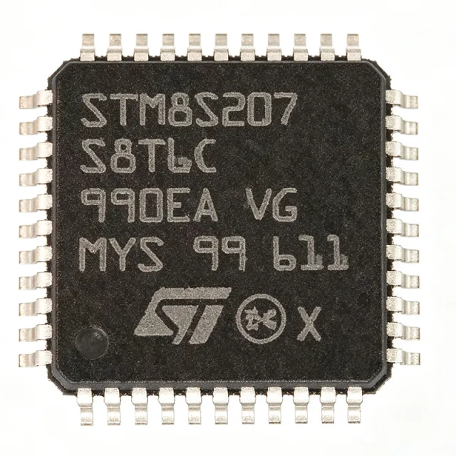
STM8S207R8T6
STM8S207R8T6 - 24MHz 8-Bit MCU 64KB Flash | STMicroelectronics
The STMicroelectronics STM8S207R8T6 is a 24 MHz, 8-bit STM8S20xxx performance-line microcontroller with 64 KB of Flash program memory, integrated EEPROM, and a 64-pin LQFP package. It executes up to 20 MIPS at 24 MHz and combines an advanced 10-bit ADC with timers, two UARTs, SPI, I²C, and CAN connectivity.
An 8-bit microcontroller is a compact processor optimized for embedded control, measurement, communications, and automation. The STM8S207R8T6 belongs to STMicroelectronics' STM8S family and is positioned as a high-density performance-line device. Its combination of EEPROM, serial peripherals, and CAN support allows designers to consolidate control logic that would otherwise require several discrete components.
Principal features include a 24 MHz maximum CPU frequency, 64 KB of Flash memory, integrated EEPROM, and 10-bit analog-to-digital conversion. The device also provides 38 I/O ports, two UART interfaces, SPI and I²C serial buses, and CAN capability. A 3 V to 5.5 V operating-voltage range supports both 3.3 V and 5 V system architectures while allowing integration across industrial controls, communications equipment, and consumer products.
The STM8 architecture provides a direct execution path for embedded firmware without an external instruction-memory interface. Hardware peripherals support serial data exchange, analog measurement, timing, and bus communication, reducing external component count and helping consolidate application logic. Maximum CPU operation at 24 MHz provides 20 MIPS of nominal instruction throughput, which is useful for responsive control loops and protocol handling.
Typical applications include industrial automation controllers, CAN-connected equipment, serial data concentrators, motor and process control, programmable logic controllers, and compact consumer appliances. Its three principal bus and communication resources—UART, SPI, and I²C—support sensors, displays, transceivers, and external nonvolatile storage, while the 10-bit ADC supports analog monitoring.
Design the PCB with short, terminated clock routes, decoupled supply pins, and a continuous ground plane. Confirm peripheral multiplexing, alternate-function assignments, and the 64-pin package pinout against the manufacturer documentation before finalizing routing. Firmware validation should include startup timing, watchdog behavior, bus contention, and CAN termination requirements for the selected system topology.
This page consolidates the device's principal specifications, same-package replacement options, application guidance, and design considerations into a practical engineering reference. It also distinguishes verified electrical attributes from parameters that still require confirmation from the official STM8S207x datasheet and reference manual.
RFQ
پەیوەندی