Schnittstellen-ICs
Unterkategorien
Produkte (1151)

ADV7391BCPZ - 10-Bit SD/HD Video Encoder | Analog Devices
The ADV7391BCPZ is a low power, chip scale 10-bit SD/HD video encoder from Analog Devices, designed for converting digital video data into analog composite (CVBS), S-Video (Y-C), or component (YPrPb) signals. It integrates three 2.7 V/3.3 V 10-bit video DACs on a single monolithic chip, supporting a wide range of video standards including NTSC, PAL, and 720p/1080i HDTV formats. The device operates from a 1.71 V to 3.63 V supply, draws only 81 mA typical current, and is housed in a compact 32-lead LFCSP-VQ (5x5 mm) package, making it ideal for space-constrained applications. A video encoder is an integrated circuit that converts digital video data into analog video signals for display or transmission. It sits between a digital video source (such as a processor, FPGA, or camera) and an analog display or recording device. The ADV7391 belongs to the video encoder family, which is a subset of interface ICs, and ultimately falls under the broader category of mixed-signal semiconductors. Understanding this hierarchy helps engineers place the component within a system's signal chain. Key features of the ADV7391BCPZ include three 10-bit DACs with a sampling rate of 297 Msps, enabling high-definition video output. It supports both SD and HD formats, with automatic detection of input video standards. The device also includes a programmable filter for image enhancement, and a flexible digital input interface that accepts 8-bit or 16-bit data with separate HSYNC and VSYNC signals. Its low power consumption of 81 mA makes it suitable for battery-powered or thermally constrained designs. Technically, the ADV7391 uses a high-speed digital-to-analog conversion architecture with on-chip interpolation filters to reduce image artifacts. The three DACs can be configured independently, allowing simultaneous CVBS and S-Video outputs, or component YPrPb output. The device operates over the industrial temperature range of -40°C to +85°C, ensuring reliability in harsh environments. The LFCSP package provides excellent thermal performance and a small footprint, with an exposed pad for enhanced heat dissipation. Typical applications include set-top boxes, video players, displays, surveillance systems, and video conferencing equipment. The ADV7391 is particularly well-suited for designs that require both SD and HD analog output from a single chip, such as multi-standard video converters. Its low power and small size also make it attractive for portable video devices. When designing with the ADV7391, ensure proper decoupling of the power supply pins with 0.1 uF capacitors placed close to the device. The digital input timing must match the device's requirements for PCLK, HSYNC, and VSYNC to avoid glitches. Also, note that the ADV7391 is not recommended for new designs (NRND), so consider alternative parts for new projects.

AK2345 - CTCSS Encoder/Decoder 24-VSOP | AKM Semiconductor
The AKM Semiconductor AK2345 is a CTCSS (Continuous Tone Controlled Squelch System) encoder/decoder IC with integrated voice signal processing, housed in a 24-pin VSOP (VSOP-24) plastic package. It supports up to 50 programmable sub-audible tone frequencies in the 67 Hz to 254.1 Hz range, compliant with the TIA/EIA-603 land-mobile-radio standard, and operates from a digital supply of 1.8 V to 5.5 V with CMOS process technology. What is a CTCSS encoder/decoder? In two-way radio systems such as FRS, GMRS, PMR446, and amateur repeater networks, multiple users share a single channel; CTCSS (Continuous Tone Controlled Squelch System, sometimes called PL or Private Line) superimposes a sub-audible low-frequency tone below 300 Hz on the transmitted audio. Receivers with CTCSS squelch only open for signals carrying the matching tone, blocking co-channel interference from other users on the same frequency. The AK2345 is a single-chip solution in the broader family of analog/mixed-signal Interface ICs (sub-category: Audio Codecs / Telecom circuits) that combines the tone encoder/decoder with the surrounding voice-path conditioning such as limiter, splatter filter, and pre-emphasis/de-emphasis. Key features include a built-in high-speed tone decoder with typical decode latency of 150 ms at 67 Hz, programmable EEPROM-backed tone table supporting up to 50 standard EIA/TIA-603 frequencies, integrated voice signal circuits (limiter, splatter filter, compressor), and a single-function CMOS architecture designed for compact FRS handheld transceivers. The device's tone decoder bandwidth and hysteresis are factory-trimmed, simplifying firmware and reducing host-MCU cycles. From an architectural standpoint, the AK2345 separates the analog voice path (limiter/splatter/pre-emphasis) from the digital tone-detection path (bandpass filter, envelope detector, frequency comparator). This split-path approach allows the host processor to read decoded-tone status via serial interface while the audio path remains continuously conditioned, eliminating host-side DSP overhead. Typical applications include FRS (Family Radio Service) and PMR446 handheld transceivers, repeater controllers, sub-audible-tone signalling in commercial land-mobile radios, and CTCSS-equipped amateur radio repeaters. Wide supply range and low CMOS power dissipation suit portable battery-operated equipment. Designers should note that the AK2345 expects a serial-control host for tone-table programming at startup; an external EEPROM or MCU-driven configuration routine is required. Bypass the analog supply pin with a 0.1 uF ceramic capacitor placed within 5 mm of the package pin. This page synthesizes distributor pricing, drop-in alternatives from the AKM CTCSS family, and practical design notes not found in the bare manufacturer datasheet.

AK4113VF - 24-Bit 216kHz DIR Audio Receiver | AKM
Asahi Kasei Microsystems AK4113VF is a 24-bit stereo digital audio receiver with a 6:1 input selector and support for sampling rates up to 216kHz. It receives digital audio streams, decodes channel-status information, and provides an audio interface for downstream signal processing. The device is identified as a 192kHz 24-bit DIR with 6:1 selector in the retrieved product documentation. A digital audio interface receiver, or DIR, converts a serial digital-audio stream into a form suitable for the next stage of an audio system. In the hierarchy of audio semiconductors, a DIR is a digital-audio input interface, while a DAC is its complementary digital-to-analog converter. The AK4113VF is therefore positioned between an upstream digital source and downstream audio processing, conversion, or monitoring circuitry. The verified information identifies the AK4113VF as a 24-bit stereo receiver supporting rates up to 216kHz and providing a 6:1 selector. The retrieved technical description also states that the channel-status decoder supports consumer and professional modes and that the device automatically detects non-PCM bit streams. These features make it relevant to professional audio equipment, broadcast infrastructure, studio converters, and digital audio routing systems. The AK4113VF is not a power semiconductor, so a safe-operating-area chart is not applicable. Its package and electrical details must be confirmed against the manufacturer datasheet for the exact ordering variant. The retrieved datasheet listing identifies the package as a 30-pin VSOP with 0.65mm pitch. The available product results also reference an evaluation board and associated control, clock, and serial-interface signals. A typical signal chain places the AK4113VF after a digital-audio source and before a DAC, audio codec, DSP, or monitoring interface. The 6:1 selector can simplify front ends that must accept multiple digital sources, while the 24-bit representation preserves high-resolution audio data when the downstream system supports the corresponding word length. Digital input timing, grounding, and format compatibility remain the principal implementation considerations. This product page combines the verified AK4113VF datasheet identity, distributor listings, package information, and cross-reference search results. It also records unavailable parameters explicitly rather than estimating them, helping engineers compare the receiver against candidate replacements and evaluate whether a new PCB design or a qualified substitute is required.
AK4621EF - 24-bit 192kHz Stereo Audio CODEC | Asahi Kasei Microdevices
The Asahi Kasei Microdevices AK4621EF is a high-performance 24-bit stereo audio CODEC supporting up to 192 kHz recording and playback, housed in a 30-pin VSOP (LSSOP) surface-mount package. It integrates two channels of ADC and two channels of DAC on a single die, with 115 dB dynamic range on both ADC and DAC paths and supports sample rates from 8 kHz to 192 kHz. An audio CODEC is a single integrated circuit that combines an analog-to-digital converter (ADC), digital-to-analog converter (DAC), and the necessary clocking, filtering, and serial interface logic to move bidirectional audio between the analog and digital domains. In the broader component taxonomy, the AK4621EF belongs to the audio interface IC family, which sits under interface ICs and ultimately under integrated circuits. It is a sub-category of audio ICs and is specialized for professional and consumer high-fidelity stereo capture and reproduction. Key features include AKM's Enhanced Dual-Bit ADC architecture for high dynamic range and the Advanced Multi-Bit DAC architecture combined with a Switched Capacitor Filter (SCF) that suppresses out-of-band noise and improves jitter tolerance. The serial audio interface is compatible with common I2S, left-justified, and right-justified formats, and the analog supply operates from 4.75 V to 5.25 V while the digital supply operates from 3.0 V to 3.6 V. The device also includes a low-latency digital filter option and a hardware-selectable HPF for DC-offset removal on the ADC path. The architecture combines sigma-delta modulators for both ADC and DAC with on-chip digital decimation and interpolation filters. The SCF output stage of the DAC removes many of the high-frequency images associated with conventional oversampling DACs, reducing the need for aggressive external post-filtering. This combination delivers wide dynamic range with low distortion at full-scale, which is critical for transparent studio capture and playback. Typical applications include Pro Audio sound cards, Digital Audio Workstations (DAWs), DVD-R, hard-disk, and CD-R recording and playback systems, as well as musical instrument recording. The combination of high dynamic range, low latency mode, and integrated PLL makes it suitable for both consumer recording devices and semi-professional production equipment. When designing with this part, observe the separate analog and digital supply domains (5 V analog, 3.3 V digital) and decouple each with appropriate bulk and bypass capacitance. The hardware mode pins configure audio data format, master/slave clocking, and HPF behavior; review them before PCB layout because they cannot be changed in software. This page synthesizes distributor pricing, drop-in and equivalent options, and practical layout guidance beyond what is printed in the manufacturer datasheet.

ALC5660-CG - 106dB SNR Stereo Audio Codec w/ HP Amp | Realtek
The Realtek ALC5660-CG is a high-performance, low-power stereo audio codec with an integrated Class-G headphone amplifier, packaged in a surface-mount QFN and specified for 106 dB SNR with a 24-bit I2S/PCM digital interface. It accepts stereo digital audio over I2S/PCM and drives line outputs, headphone loads, and microphone inputs through on-board ADCs, DACs, and a flexible analog mixing block. The device targets portable and embedded designs where board space, BOM cost, and audio fidelity must coexist with strict power budgets. An audio codec is a mixed-signal integrated circuit that bridges the digital audio domain (typically I2S, PCM, TDM, or S/PDIF streams) and the analog audio domain (headphones, line-level outputs, microphones, and line-level inputs). Inside the codec, multi-bit sigma-delta ADCs digitize analog microphone and line-in signals, while multi-bit sigma-delta DACs reconstruct analog waveforms from the incoming digital stream. The ALC5660 belongs to the broader hierarchy of audio interface ICs > interface ICs > signal chain ICs > mixed-signal semiconductor; codecs are distinguished from pure DACs or ADCs by their bidirectional stereo architecture and integrated mixer, microphone preamplifier, and (in this case) headphone driver. Key features of the ALC5660-CG include a 106 dB SNR DAC, 24-bit resolution across the digital audio interface, integrated headphone amplifier with ground-referenced Class-G topology, support for microphone bias and digital microphone inputs, and a flexible digital mixing engine. The Class-G amplifier dynamically scales the internal supply rail to match the instantaneous headphone output level, sharply reducing quiescent dissipation during quiet passages while still delivering ample headroom for peaks. Technically, the ALC5660 uses multi-bit sigma-delta modulator cores for both the record (ADC) and playback (DAC) paths, with on-chip digital decimation/interpolation filters. The headphone path uses a charge-pump-derived negative rail and a dynamically switched supply to maximize efficiency at low output levels. All gain, mixing, and routing is controlled through a two-wire (I2C-style) control interface. Typical applications include tablets, ultrabooks, docking stations, portable media players, USB-C headsets, and single-board computer audio hats. The QFN package and integrated HP amp minimize PCB area, while the high SNR suits music playback and VoIP. Design consideration: the Class-G topology relies on adequate bulk decoupling near the HP supply pins, and the digital I2S/PCM bus should be length-matched and routed away from the analog headphone outputs to preserve SNR. This page consolidates distributor pricing, drop-in alternative candidates, and engineering design notes not available in the standalone manufacturer datasheet, helping engineers evaluate sourcing options and PCB integration in one place.

AM26C31IDR - Quad RS-422 Diff Line Driver 16-SOIC | Texas Instruments
The Texas Instruments AM26C31IDR is a quadruple differential line driver with complementary outputs, designed to meet TIA/EIA-422-B and ITU (formerly CCITT) requirements, housed in a 16-pin SOIC (D) package. The device provides four channels of TTL-to-differential RS-422 conversion with 3-state outputs, supporting data rates up to 10 Mbps and operating from a single 4.5V to 5.5V supply. Key features include ±60 mA output drive current on each channel, low supply current of 100 µA typical in disabled state, thermal shutdown protection, and complementary output pairs per driver for flexible termination topologies. The wide -40°C to +85°C industrial operating temperature range suits factory automation, building controls, and process instrumentation environments. An RS-422 line driver (also called a quadruple differential transmitter) is one of the standard building blocks in the EIA/TIA-422 balanced-voltage digital interface family. It converts a single-ended TTL/CMOS logic input into a differential pair (+Y, -Y) capable of driving long cables with strong common-mode noise rejection. RS-422 sits in a hierarchy of digital interfaces: line driver -> differential transceiver -> serial interface IC -> interface IC -> semiconductor. Compared to single-ended interfaces (RS-232, LVTTL), RS-422 supports multi-drop topologies and longer cable runs, making it the interface of choice for industrial fieldbuses, point-of-sale terminals, and motor-control feedback links. The AM26C31IDR uses a CMOS process that delivers the same electrical functionality as the classic AM26LS31 bipolar driver with substantially reduced power dissipation. Internal thermal-shutdown circuitry disables the outputs when the die temperature exceeds safe limits, protecting the device against bus contention faults. Each driver has dedicated TTL/CMOS-compatible input plus true and inverted 3-state outputs, allowing half-duplex multi-drop wiring when paired with the companion AM26C32 receiver. Typical applications include factory-floor RS-422 multidrop networks, CNC machine controller linkages, building-automation HVAC and access-control wiring, and point-to-point serial links to motion encoders. The 16-pin SOIC narrow-body footprint balances ease of hand-soldering in prototypes with high-density routing on production boards. When designing with the AM26C31IDR, place a 0.1 µF decoupling capacitor within 5 mm of the VCC pin and keep the differential pair traces length-matched to within 5 mm to maintain signal integrity at the maximum 10 Mbps signaling rate. Use a 100 Ω termination resistor across each differential pair at the receiver end to suppress reflections on cables longer than 1 m. This page synthesizes distributor pricing, drop-in alternatives (same-brand first, then cross-brand), and practical design notes not found on individual DigiKey, Mouser, or Octopart listings - giving an engineer everything needed to select, source, and implement the AM26C31IDR in one place.

AM26LS31CN - Quad RS-422 Differential Driver | Texas Instruments
The Texas Instruments AM26LS31CN is a quadruple complementary-output differential line driver with four independent driver channels, designed for ANSI TIA/EIA-422B and ITU V.11 balanced digital transmission. It is supplied in a 16-pin dual in-line package, and the verified distributor listing identifies it as an RS-422/RS-485 interface driver. Each channel provides differential outputs for driving balanced digital lines while helping reject common-mode noise present in industrial and telecommunications environments. A differential line driver is an interface IC that converts a single-ended logic signal into two complementary signals. The receiver at the far end interprets the voltage difference between those signals as the transmitted bit. This approach improves noise immunity compared with a single-ended link and allows reliable communication over longer cable runs when the driver, receiver, termination, and cable characteristics are correctly matched. The AM26LS31 belongs to the broader line-driver and digital-interface hierarchy. The AM26LS31CN family provides four channels in one package, reducing component count and simplifying point-to-point or multidrop RS-422 interface designs. Its complementary outputs are intended for balanced line operation, while the driver-side logic interface connects to a digital controller, transmitter, or test system. Because the verified results identify the device as a quadruple line driver but do not provide complete electrical tables, values such as output voltage, propagation delay, supply current, and temperature limits are retained as data-needed items rather than estimated. Typical uses include industrial control links, instrumentation, communications equipment, test systems, and embedded data transmission where balanced signaling is preferred. Four channels allow the same package to support multi-wire links or several independent point-to-point connections. In practice, the receiving device should provide the complementary differential inputs, and the physical layer should follow the applicable cable and termination requirements. A critical design consideration is confirming that the receiver, cable, and termination scheme are appropriate for the intended RS-422 application. Keep the line-driver outputs routed as a matched differential pair, minimize unnecessary stubs, and provide a suitable ground/reference strategy. The 16-pin through-hole package is also mechanically different from modern surface-mount options, so a replacement is only drop-in when both the footprint and pinout are identical. This page combines the verified manufacturer and distributor links, package and interface information, practical application guidance, and a strict comparison of only same-footprint drop-in candidates. It does not infer electrical specifications or lifecycle claims that were not present in the supplied data.
AM26LV32IDR - 32MHz 3.3V Quad RS-422 Receiver | TI
The Texas Instruments AM26LV32IDR is a low-voltage, high-speed quadruple differential line receiver with four independent receivers, 3-state outputs, and a 16-pin SOIC package. It operates from a single 3.0 V to 3.6 V supply, supports switching rates up to 32 MHz, and is designed for balanced bus transmission similar to TIA/EIA-422-B and ITU Recommendation V.11 receivers. A differential line receiver is an interface circuit that converts a balanced differential signal into a single-ended logic signal while rejecting common-mode noise. In the interface hierarchy, it belongs to the receiver class of RS-422 interface ICs, which sit between a physical communication bus and digital logic. The AM26LV32IDR is optimized for low-voltage, high-speed point-to-point or multidrop communication where four channels must be received in one package. Key features include four differential receivers, a common enable control for all outputs, and 3-state output capability for bus isolation. The BiCMOS architecture combines low power dissipation with high switching performance. The device is specified for a 3.3 V supply, making it suitable for systems whose digital core operates from the same voltage rail. Its 32 MHz maximum switching rate supports substantially faster signaling than conventional low-speed RS-422 receivers. The AM26LV32 family is intended for balanced differential buses and point-to-point data links. Its reduced common-mode voltage range is a consequence of the low supply voltage, so the complete bus voltage and grounding plan must remain within the device's specified operating limits. The common enable function allows the receiver outputs to enter a high-impedance state when the host needs to isolate the interface. Typical uses include industrial automation equipment, test and measurement instruments, computer peripherals, data acquisition systems, and multi-channel communication links. Because each channel is independent, the IC can also serve monitoring, redundant sensing, or distributed input systems where four differential signals share a common supply. When laying out a board, keep the differential traces short, matched, and continuous over a common ground reference. Place receiver bypass capacitors close to the supply pins and follow the manufacturer's recommended termination and protection practices. Verify that the driver, cable, connector, and receiver common-mode limits remain compatible across temperature and supply tolerance. This page combines the verified manufacturer, distributor, and cross-reference data with practical interface selection guidance, package information, and design notes that are not presented as a simple replacement for the complete TI datasheet.

AQR107-B0-EG-Y - 10G/5G/2.5G/1G/100M Multi-Gig Ethernet PHY | Marvell
The Marvell AQR107-B0-EG-Y is a single-port, multi-gigabit Ethernet PHY transceiver supporting 10G, 5G, 2.5G, 1G, and 100M operation over IEEE 802.3 compliant interfaces, housed in a compact 7 mm x 11 mm flip-chip BGA (FCBGA) package. It delivers full backward compatibility with legacy NBASE-T and 1000BASE-T/100BASE-TX networks while enabling 10G speeds over Cat6a cabling, making it the Gen2 member of Marvell's AQrate PHY family. An Ethernet PHY (Physical Layer transceiver) is the lowest layer of the OSI networking stack; it converts digital MAC-domain data into analog line signals and recovers the clock and data on the receive side. Multi-gigabit PHYs extend the NBASE-T and IEEE 802.3bz standards to bridge the gap between 1G and 10G Ethernet, allowing enterprises to upgrade switch-to-server links without replacing existing Cat5e/Cat6 cabling. The AQR107 sits in the signal chain between the host MAC (typically a switch SoC, server NIC, or FPGA) and the magnetics/RJ45 connector. Key features include integrated baseband DSP for all supported rates, Energy Efficient Ethernet (EEE) per IEEE 802.3az, MACsec line-rate encryption capability, and a USXGMII/XFI/SGMII/RGMII host interface. The FCBGA-104 (7x11) package operates across an industrial -40C to +108C temperature range with a small footprint suitable for dense switch and adapter designs. The AQR107/AQR108/AQR109 family is pin-compatible, allowing one PCB layout to support different port counts and rate combinations. Architecturally, the device uses a DSP-based echo-cancelled full-duplex receiver, a 4-level PAM (PAM-4) modulation for 2.5G/5G, and NRZ with DFE for 10GBASE-T, with on-chip termination resistors to minimize external BOM. The B0-EG-Y suffix denotes the lead-free, extended-temperature Gen2 die revision compatible with NBASE-T and Energy Efficient Ethernet. The MACsec engine provides line-rate AES-128/256 encryption without throughput penalty for secured enterprise and data-center links. Typical applications include enterprise 10G switch downlinks, server and storage NIC adapters, Wi-Fi 6/6E/7 access point uplinks, NBASE-T aggregation switches, and industrial Ethernet backbones. Pair it with a Marvell Prestera switch SoC or a third-party 10G-capable MAC for a complete multi-gig link. When designing with the AQR107, follow Marvell reference design guidelines for magnetics selection, RJ45 footprint, and PCB stack-up; the FCBGA requires microvia construction and controlled-impedance routing. Use Marvell's AQrate configuration tools to program rate-clamp, EEE, and MACsec policy at firmware load. This page synthesizes distributor pricing, drop-in AQR10x alternatives, MACsec/PHY design notes, and AI-citation-ready FAQ passages not available on individual distributor listings.

AR8031-AL1B-R - 10/100/1000 Ethernet PHY RGMII/SGMII | Qualcomm
The Qualcomm AR8031-AL1B-R is a single-port 10/100/1000 Mbps Ethernet Physical Layer transceiver (PHY) that integrates an RGMII and SGMII MAC interface, integrated switching voltage regulator, and built-in terminations, housed in a 48-pin QFN (6x6 mm) package with exposed pad. It operates from a single 3.3V supply (with internal LDO) and supports IEEE 802.3 10BASE-T/100BASE-TX/1000BASE-T over standard CAT-5 twisted pair. What is an Ethernet PHY? An Ethernet Physical Layer transceiver (PHY) is the analog front-end device that connects a digital Media Access Controller (MAC) to the copper or fiber Ethernet medium. Within the OSI model, the PHY sits at Layer 1 and handles line coding, link training, echo/NEXT cancellation, adaptive equalization, clock/data recovery, and auto-negotiation. The PHY is a category under Ethernet transceivers -> interface ICs -> integrated circuits, and serves as the physical gateway between a processor's MAC and the RJ-45 magnetics. The AR8031-AL1B-R key features include 1 Gbps throughput, RGMII v2.0 and 1000BASE-X/SGMII MAC-side interfaces, 25 mV receiver hysteresis, automatic direction control (auto-MDI/MDIX), EEE 802.3az support, and hardware-accelerated 1588v2 / 802.1AS timestamping. It combines an echo canceller, NEXT canceller, feed-forward equalizer, joint Viterbi decoder, feedback equalizer, and timing-recovery DSP to enhance signal performance in noisy backplane and cable environments. The device integrates a 1.2V core LDO, 1.0V VDDIO LDO, and supports 3.15V to 3.45V analog supply. The exposed thermal pad QFN-48 package provides low thermal resistance (typical 28 C/W with a 4-layer JEDEC JESD51 PCB), and 4 kV HBM ESD protection on the MDI pins protects against handling and cable-discharge transients. Typical applications include industrial Ethernet switches, routers and gateways, automotive infotainment Ethernet PHYs (with NXP i.MX SoCs), 5G small-cell baseband backhaul, IP cameras / surveillance NVR, and printer/MFP embedded networking where a small footprint, low BOM, and integrated magnetics-termination are required. Design consideration: The AR8031-AL1B-R is announced as NRND/EOL by Qualcomm for new designs. For new designs, choose the pin-compatible AR8033 or AR8035 (which share the QFN-48 footprint but add 100BASE-T1 automotive PHY modes), or migrate to TI DP83867/DP83869 industrial Gigabit PHYs with software-compatible SMI/MII registers. Existing designs should plan for last-time-buy windows. This page synthesizes distributor pricing, drop-in alternative pin-for-pin cross references, and AR8031 design notes not found in the bare datasheet, including migration paths for EOL NRND devices.

AR8035-AL1B - Gigabit Ethernet PHY 40-QFN | Qualcomm
The Qualcomm AR8035-AL1B is a single-port 10/100/1000 Mbps tri-speed Gigabit Ethernet PHY integrated circuit, supplied in a 40-pin QFN with exposed pad (5x5 mm) package. According to the manufacturer datasheet, the device operates from a single 3.3 V supply, supports full-duplex and half-duplex modes, and integrates the physical-layer functions for 10 Mbps, 100 Mbps, and 1000 Mbps Ethernet as defined by IEEE 802.3. The part is qualified for commercial operating temperatures from -40 °C to +85 °C. A Gigabit Ethernet PHY (physical-layer transceiver) is a mixed-signal IC that sits between a MAC (media access controller) and the magnetic RJ45 transformer, handling line encoding/decoding, clock/data recovery, echo cancellation, and link training. The PHY belongs to the Ethernet transceiver family within the wired networking IC hierarchy, which itself sits inside the Interface IC category in power and signal management taxonomies. By integrating the analog front-end, PLL, and digital state machine in one die, the PHY replaces dozens of discrete components that earlier designs required. Key features include integrated 1000BASE-T PCS and PMA blocks, RGMII/GMII/MII MAC-side interfaces, IEEE 802.3az Energy-Efficient Ethernet (EEE) support, on-chip termination resistors, and built-in cable length estimation. The 40-QFN package provides a thermal pad for direct PCB heatsinking while keeping the footprint compact for space-constrained designs such as routers, switches, and embedded modules. The AR8035-AL1B is part of Qualcomm's (originally Atheros') AR803x Arctic family, designed for low-power Gigabit copper connectivity in cost-sensitive applications. Its 1.0 V core derived from an internal LDO minimizes external components and improves efficiency versus PHYs that expect multiple analog rails. The device also supports Synchronous Ethernet (SyncE) and Wake-on-LAN link-state signaling for managed-network and IPTV deployments. Typical applications include home gateways, Wi-Fi access points, IP set-top boxes, network switches, industrial Ethernet modules, and any embedded platform with RGMII/SGMII-capable MAC. It is commonly paired with Qualcomm IPQ series SoCs, NXP Layerscape processors, or general-purpose MPU+MAC combos for wired backhaul or LAN ports. When designing with this PHY, observe proper 100-ohm differential impedance on the MDI traces, route the analog supply separately from digital rails, and stitch a ground fence around the magnetic-transformer region to suppress common-mode emissions. This page synthesizes distributor pricing, drop-in cross-brand Gigabit-PHY alternatives, and PCB design notes not found in any single manufacturer datasheet, giving engineers a consolidated reference for sourcing and layout.

ASI4UE-E-G1-ST - AS-Interface v3.0 Universal Slave IC | Renesas
The Renesas ASI4UE-E-G1-ST is an AS-Interface (Actuator Sensor Interface) Specification v3.0 compliant universal AS-i slave IC housed in a 28-pin SOIC wide-body package. Designed as a fourth-generation CMOS AS-i transceiver for master and slave nodes, the device transports both 24 V power and digital data simultaneously over a single two-wire unshielded cable. Its 28-SOIC form factor, integrated EEPROM for node parameters, and an on-chip analog front-end make it the principal silicon solution for industrial AS-i slave modules. An AS-Interface (AS-i) IC is a specialized transceiver integrated circuit that implements the physical and data-link layers of the AS-i fieldbus. The bus was created to economically connect binary sensors and actuators over a single unshielded twisted pair, eliminating the analog I/O modules and analog wiring harnesses traditionally required in factory automation. AS-i transceivers sit between a microcontroller and the bus, handling Manchester-coded transmission, slave AC modulation/demodulation, and node addressing that complements the ASI4U IC. The ASI4UE-E-G1-ST extends this role with full AS-i v3.0 compliance and A²SI pin compatibility for migration from older 3rd-party AS-i slave ASICs. Key features include AS-Interface Complete Specification v3.0 compliance, integrated non-volatile EEPROM for storage of slave parameters and node address, an AS-i safety option for short response times on safety-related events, A²SI function and pin compatibility, programmable by stationary or handheld programming devices, and operation over the industrial -40C to +85C temperature range. The wide-body 28-SOIC package facilitates robust through-hole-style PCB mounting for the high-voltage industrial environment associated with the 24 V AS-i bus rail. Architecturally, the ASI4UE-E-G1-ST combines a high-voltage bus transceiver front-end, an analog modulator/demodulator block implementing the AS-i AC current modulation scheme, a Manchester encoder/decoder, an integrated oscillator, and a serial peripheral interface (SPI) for connection to an external microcontroller. Configuration data, the AS-i slave address, and ID codes are stored in the internal EEPROM, which is programmable in-circuit by a handheld or stationary programmer. The special AS-i safety option provides deterministic short response times for safety-at-work applications. Typical applications include industrial binary sensor modules, industrial valve manifolds, indicator lights and stack lights, AS-i safety modules, AS-i gateway modules, AS-i slave I/O blocks, and AS-i repeater systems. When designing with the ASI4UE-E-G1-ST, place 100 nF decoupling close to VCC and follow the reference PCB layout in the datasheet to meet EMI/EMC compliance. The integrated oscillator minimizes external components and the EEPROM eliminates external parameter memory. This page synthesizes distributor pricing, drop-in alternatives, and practical AS-i bus design notes not found in the manufacturer datasheet.
ASI4UE-G1-SR - AS-Interface v3.0 Universal AS-i IC | Renesas
The Renesas ASI4UE-G1-SR is a next-generation CMOS integrated circuit designed for AS-Interface (AS-i) networks, fully compliant with the AS-Interface Complete Specification v3.0. Housed in a surface-mount SOIC-28 package, the ASI4UE-G1-SR functions as part of a master or slave node and provides the physical interface, power-supply management, and protocol handling for the AS-i field bus. It transports both 24 VDC power and digital data simultaneously over a single two-wire unshielded cable, supporting up to 31 standard slaves per master with cycle times down to 5 ms. An AS-i (Actuator Sensor Interface) IC is a specialized mixed-signal controller used in industrial automation to replace parallel wiring between sensors/actuators and a PLC. The bus category hierarchy is: AS-i IC -> industrial fieldbus transceiver -> sensor/actuator interface -> industrial communication IC -> semiconductor. Compared with conventional point-to-point wiring, AS-i reduces cabling cost and weight, supports automatic slave addressing, and enables diagnostic data collection from each node. The ASI4UE-G1-SR's on-chip EEPROM stores all slave configuration parameters, allowing rapid programming via stationary or handheld programming devices. Key features include an integrated differential physical layer for the AS-i bus, an embedded Manchester-coded protocol engine, an internal DC-DC converter that derives a regulated logic supply from the bus voltage, four configurable digital I/O lines with input-monitoring capability, and a dedicated safety option that guarantees short response times for safety-related events. The IC supports up to 4 standard slaves per AS-i master and can be cascaded for larger networks. Architecturally, the ASI4UE-G1-SR combines a high-voltage bus transceiver, a precision current source, an 8-bit microcontroller-compatible interface, and the safety-state machine in one CMOS die. This level of integration eliminates the need for an external ASIC or microcontroller in simple slave implementations, lowering BOM cost and PCB area. The device operates over the -25 °C to +85 °C industrial temperature range. Typical applications include binary sensor/actuator modules in factory automation, AS-i safety I/O blocks, conveyor-system edge nodes, packaging machinery, and AS-i stack-light modules. The device is function- and pin-compatible with the legacy A²SI IC family, allowing drop-in migration of existing AS-i slave designs. When designing with the ASI4UE-G1-SR, observe the recommended PCB layout guidelines from the datasheet: keep the bus traces short and symmetric, place the bus-decoupling capacitor within 5 mm of the IC, and provide adequate creepage/clearance for the 24 V industrial environment. Always validate safety-related designs against the AS-i Safety Specification. This page synthesizes distributor pricing, drop-in alternatives, and practical design notes that go beyond the manufacturer datasheet to accelerate AS-i slave and master integration.

ASM1083 - PCIe x1 to 32-bit PCI Bridge | ASMedia Technology Inc.
The ASMedia Technology Inc. ASM1083 is an x1 PCI Express to 32-bit PCI forward bridge controller that enables designers to connect legacy parallel PCI bus devices to modern PCI Express serial interfaces. Housed in an LQFP-128 package, the ASM1083 is fully compliant with the PCI-SIG PCI Express-to-PCI Bridge Specification 1.0, making it the industry-standard solution for adding legacy PCI card support to PCIe-based motherboard designs. A PCI Express-to-PCI bridge is a type of interface bridge IC in the broader family of bus interface integrated circuits. Its role in the system hierarchy is to translate protocol transactions between a high-speed serial root complex (PCIe) and the older shared-parallel-bus PCI (Conventional PCI, 32-bit/33 MHz) domain, preserving investment in legacy add-in cards such as audio cards, RAID controllers, industrial I/O, and capture cards. Key features of the ASM1083 include its x1 PCI Express downstream port operating at 2.5 GT/s, support for 32-bit conventional PCI bus operation at up to 66 MHz [DATA_NEEDED: exact PCI frequency modes], integrated PHY and MAC for the PCIe interface, and compliance with the PCI-SIG PCI Express-to-PCI Bridge Specification 1.0. Single-chip integration eliminates the need for external glue logic, reducing bill-of-materials cost and board area. Architecturally, the device implements a forward bridge: transactions originating on the PCIe side are translated and forwarded to the conventional PCI bus, and responses are returned upstream. The bridge handles configuration space mapping, bus numbering, and transaction ordering per PCI-SIG rules. [DATA_NEEDED: power supply voltages, quiescent current, and detailed operating characteristics from the full datasheet] Typical applications include desktop motherboards that retain one legacy PCI slot, PCIe-to-PCI riser and adapter cards, industrial backplanes and SBCs that must accept legacy PCI I/O modules, and retro/legacy audio expansion cards where the ASM1083 sits between the PCIe edge connector and a legacy PCI audio codec. When designing with the ASM1083, verify clocking requirements and power-management behavior; community reports note compatibility issues when aggressive PCIe power-saving (ASPM) states are enabled on some adapters, so disabling ASPM or validating L-state handling is advisable for audio and real-time capture cards. This page synthesizes distributor sourcing data, the PCI-SIG bridge compliance statement from the manufacturer product page, and practical design notes not found in the datasheet summary.

ASM1166 - PCIe Gen3 x2 to 6-Port SATA Controller | ASMedia
The ASMedia ASM1166 is a SATA host controller (AHCI) IC with an upstream PCIe Gen3 x2 interface and six downstream SATA Gen3 (6 Gbps) ports, housed in a QFN-88 10x10 mm surface-mount package. According to the ASMedia product page, it is a low-latency, low-cost, low-power AHCI controller supporting cascaded port multipliers. A SATA host controller is a type of storage interface IC, or disk controller, within the broader family of PCIe bridge and interface controllers used in the storage I/O subsystem of computers and servers. It translates PCI Express transactions into SATA AHCI command traffic, allowing a system with limited native SATA ports to attach many more drives. The AHCI (Advanced Host Controller Interface) standard means the device is recognized natively by modern operating systems without vendor-specific drivers, which is a major advantage for NAS and home-lab builders. Key features include six independent SATA 6 Gbps ports from a single PCIe Gen3 x2 upstream link (approximately 2 GB/s aggregate bandwidth, shared across ports), support for cascaded port multipliers to expand beyond six physical drives, low power consumption suited to always-on storage systems, and native AHCI 1.3.1-class operation in Linux, Windows, and BSD kernels. Architecturally, the ASM1166 integrates a PCIe Gen3 PHY and MAC on the upstream side, a packet arbitration engine, and six SATA 3.x PHY/MAC channels downstream. Because the x2 upstream link is the bottleneck (~1.97 GB/s raw), per-port throughput is highest when workloads are spread across disks rather than concentrated on one drive, and sequential multi-drive reads saturate the upstream link. Typical applications include NAS (Network Attached Storage) builds on Unraid, TrueNAS, and OpenMediaVault, server and high-capacity storage platforms, surveillance and video-recording systems, and adding drive bays to mini-PCs via M.2-to-SATA adapter cards. Design-wise, route the six SATA differential pairs with controlled impedance (100 ohm differential), keep pairs length-matched, and provide a solid ground reference; the exposed pad must be soldered to ground for thermal and electrical integrity. Firmware is typically flash-resident on an attached SPI ROM, so include the flash on the BOM. This page synthesizes distributor availability, community-verified comparisons against JMB585 and LSI HBAs, and practical design notes not found in the brief manufacturer datasheet listing.
ASM2364 - 20Gbps USB to PCIe 3.0 x4 NVMe Bridge | ASMedia
The ASMedia ASM2364 is a USB 3.2 Gen 2x2 to PCI Express Gen 3 x4 NVMe bridge controller with up to 20Gbps USB bandwidth, four-lane PCIe connectivity, and a QFN-88 10x10 mm package. It integrates ASMedia USB 3.2 Gen 2x2 and PCI Express Gen 3 PHYs and translates NVMe storage traffic between a USB Type-C host connection and an internal M.2 solid-state drive. The controller targets external SSDs, onboard SSDs, PCs, laptops, servers, docking stations, and embedded systems. A USB-to-PCIe NVMe bridge is a semiconductor controller that lets an NVMe drive use a USB interface instead of a conventional internal PCIe port. In the system hierarchy, ASM2364 is an interface controller, storage interface bridge, USB controller, PCIe endpoint, and NVM Express device controller. Its Gen 2x2 USB interface provides two 10Gbps lanes, while its PCIe Gen 3 x4 side supplies four PCI Express lanes for a high-bandwidth storage path. The verified manufacturer information identifies USB 3.2 Gen 2x2, PCI Express Gen 3 x4, one USB device port, and integrated USB and PCIe PHYs as the central features. ASMedia describes ASM2364 as its second-generation PCI Express-to-USB 3.2 device controller. Advanced power saving is supported through USB and PCI Express link power management together with chip power management, making the device suitable for systems where energy use and thermal performance matter. The controller supports NVM Express Base Specification Revision 1.3c, PCI Express Base Specification Revision 3.1a, and USB 3.2 Specification Revision 1.0 according to the provided datasheet result. Its high-speed lanes are intended to maximize transfer throughput while retaining compatibility with NVMe M.2 SSDs used in external and embedded storage products. Actual sustained transfer speed still depends on the SSD, host controller, cable, enclosure, firmware, and thermal conditions. Typical implementations place ASM2364 between a USB Type-C receptacle and an M.2 NVMe socket. The same architecture can support external SSD enclosures, internal PC or laptop storage, server storage adapters, docking stations, and embedded systems. The QFN-88 package is compact relative to the interface bandwidth, but high-speed differential routing, power integrity, grounding, thermal design, and connector signal integrity remain critical. Designers should validate the complete USB Type-C cable and host path because 20Gbps operation requires a USB 3.2 Gen 2x2 host connection. PCB layout must follow the manufacturer reference guidance, preserve impedance-controlled differential pairs, provide continuous return paths, and place decoupling and clock circuitry according to the datasheet. Firmware and NVMe compatibility should also be verified before production release. This page consolidates the verified manufacturer description, package information, storage use cases, comparison caveats, and practical integration guidance. It separates documented facts from unavailable details, avoiding unsupported assumptions about pin assignments, electrical ratings, lifecycle status, or unverified drop-in replacements.

ASM2464PDX - USB4/TB to PCIe Gen4 x4 NVMe Bridge | ASMedia
The ASMedia ASM2464PDX is a USB4/Thunderbolt to PCIe/NVMe accessory bridge controller delivering 40 Gbps over USB4/Thunderbolt and tunneling PCIe Gen4 x4 to NVMe SSDs or general PCIe devices, housed in a compact RoHS-green BGA package (FCCSP-273, 10x10 mm class per distributor listings). A bridge controller is a protocol-conversion IC that sits between a host interface and a device interface, translating one bus protocol into another. In the USB4 ecosystem, bridge controllers let legacy protocols such as PCI Express ride inside the USB4/Thunderbolt fabric, where USB4 router-to-router tunnels carry PCIe and USB transactions transparently across the domain. Within the power-management-and-connectivity hierarchy of a host system, the ASM2464PDX functions as the device-side endpoint router of a USB4/Thunderbolt daisy chain. Key features include in-house designed ASMedia USB4/Thunderbolt PHYs, native PCIe Gen4 x4 downstream connectivity for maximum NVMe throughput, and support for USB4, Thunderbolt 3, and USB 3.x legacy host operation. The PDX variant specifically targets general PCIe devices in addition to NVMe SSDs, making it the ASMedia part of choice for Thunderbolt/USB4 eGPU docks and expansion enclosures. Technically, the ASM2464PDX integrates the USB4/Thunderbolt Gen3 x2 PHY and the PCI Express Gen4 PHY with VDD, VCCL, and VCCH voltage domains. It is clocked from a local 25 MHz crystal, supports multiple GPIO pins for platform customization, and integrates the protocol routers needed to encapsulate PCIe and USB traffic into USB4 tunneling. Typical applications include USB4/Thunderbolt NVMe SSD enclosures, Thunderbolt eGPU adapters, PCIe accessory expansion docks, and high-speed developer/debug hardware that exposes general PCIe lanes over a single USB-C cable. Design consideration: the PDX suffix denotes an improved variant of the ASM2464PD focused on power-delivery stability and reduced thermal throttling under sustained high-bandwidth loads such as eGPU traffic; board designs should still provide solid VCCL power planes and thermal relief for sustained Gen4 x4 transfers. This page synthesizes distributor availability, the documented PD-vs-PDX differences, competitor context (Intel JHL7440/JHL9480), and practical design notes not found in the manufacturer datasheet.

ASM58048 - 48-Lane 16-Port PCIe 4.0 Switch | ASMedia Technology
The ASMedia Technology ASM58048 is a 48-lane, 16-port PCIe Packet Switch fabricating a high-speed PCI Express interconnect switching fabric for AI, server, storage, and workstation platforms. First showcased at COMPUTEX 2025 and sampled in Q3 2025, it belongs to ASMedia's PCIe packet switch roadmap covering all PCIe generations with a product line ranging from 3 to 80 lanes. According to the PCI-SIG integrator listing, the ASM58048 identifier is registered as a 48-lane, 16-port PCIe Switch function. A PCIe packet switch is a switching fabric device that sits in the PCI Express hierarchy between a host root complex and multiple endpoints. It performs store-and-forward or cut-through packet routing of TLPs (Transaction Layer Packets), enabling one upstream port to fan out to several downstream ports. In the system hierarchy, the device spans PCIe switch -> interconnect fabric -> host interface -> high-speed serial interface -> semiconductor. Key characteristics include 48 lanes of PCIe connectivity and 16 configurable ports, giving system architects flexible bifurcation options for connecting multiple NVMe SSDs, GPUs, or network adapters to a limited number of host CPU lanes. ASMedia states that full compatibility and performance comparable to international competitors were design targets, and that the device's own fully verified PHY technology underpins the silicon. The architecture leverages ASMedia's in-house PHY IP, and the follow-on PCIe Gen5 product with independently verified PHY is nearing design finalization, indicating the ASM58048 targets the PCIe Gen4 class of interconnect workloads. Typical applications include NAS high-speed cache acceleration - per ASMedia's CES 2026 announcement, the ASM58048 enables multiple high-speed NVMe SSDs to be connected at the NAS front end forming a high-speed cache tier for AI data preprocessing - plus AI workstation GPU expansion, server storage backplanes, and add-in-card fan-out designs. When designing with this device, confirm lane allocation and bifurcation settings against your board's power and reference-clock topology, and validate link training across all 16 ports in system-level bring-up. This page synthesizes PCI-SIG registration data, manufacturer press releases, and drop-in replacement guidance not found in distributor listings.

AT97SC3205T-U3A17-AA - TPM I2C Security Module | Microchip
The Microchip AT97SC3205T-U3A17-AA is a fully integrated Trusted Platform Module (TPM) security IC designed to be embedded into computer and embedded systems for hardware-rooted cryptographic functions. Housed in a 28-pin SSOP package, this device conforms to the Trusted Computing Group (TCG) Trusted Platform Module Main v1.2, r116 specification and is intended for I2C-compliant host integration, providing secure key storage, platform authentication, and integrity measurement. What is a TPM? A Trusted Platform Module is a dedicated hardware security controller that provides tamper-resistant storage for cryptographic keys, secure generation of RSA keys up to 2048 bits, platform integrity measurement via SHA-1/SHA-256, and remote attestation. The TPM sits on the I2C bus as a peripheral to the host CPU and occupies a unique position in the security hierarchy: hardware root of trust -> security module -> platform security -> system integrity. AT97SC3205T-U3A17-AA implements this hierarchy in a single low-power CMOS device. Key features of the AT97SC3205T-U3A17-AA include RSA key generation up to 2048-bit keys, SHA-1 and SHA-256 hash engines for platform integrity, hardware random number generator, secure key storage with hardware tamper detection, I2C host interface for low-pin-count integration, and an integrated firmware that is field-upgradable through a secured loader. The device operates from a single 3.3V supply and uses CMOS technology for low quiescent current. The AT97SC3205T family is positioned for desktops, laptops, embedded industrial PCs, and other systems that require TCG 1.2 compliance (note: not TCG 2.0). Designers select this part when TCG Main v1.2 r116 compliance is mandated by procurement specifications, by Microsoft Windows Vista/7 era certification requirements, or by embedded OEMs whose customers require TPM presence in the BOM. Because TPM 2.0 has largely replaced 1.2 in new designs, this part serves legacy systems, industrial security appliances, and embedded markets where long-life TCG 1.2 platforms are standard. Typical applications include commercial desktop and laptop motherboards, industrial PCs and HMIs, point-of-sale terminals, secure printing devices, and embedded security appliances. The I2C interface allows integration with both x86 chipsets and ARM-based SoCs that expose I2C. For TCG 2.0 systems, consider AT97SC3205T family members with TCG 2.0 compliance or the newer AT97SC3205 family variants. When designing with the AT97SC3205T-U3A17-AA, the host driver stack must match the TCG 1.2 specification; Linux drivers (tpm_tis_i2c) and Windows TBS (TPM Base Services) provide the OS-level interface. The I2C lines require pull-up resistors per I2C specification, and the TPM's GPIO/PIR (presence) pin must be wired to the platform's TPM-presence detection logic. Power sequencing: VCC must stabilize before the host begins I2C transactions. This page synthesizes distributor availability, parametric alternatives within the same SSOP-28 footprint, and platform-integration design notes drawn from manufacturer reference documentation - content not found in the standalone datasheet.

ATA6563-GAQW1 - High-Speed CAN FD Transceiver SOIC-8 | Microchip
The Microchip ATA6563-GAQW1 is a high-speed CAN FD transceiver providing an interface between a CAN protocol controller and the physical two-wire CAN bus. Housed in an 8-pin SOIC package, the device supports CAN FD data rates up to 5 Mbit/s and operates from a 5V nominal supply across an ambient temperature range of -40C to +150C (AEC-Q100 Grade 0). The integrated VIO pin and Wake-Up Pattern (WUP) function provide low-power standby capability with bus wake-up, enabling nodes to remain quiescent while still monitoring the CAN bus. A CAN FD transceiver (Controller Area Network with Flexible Data-Rate) is the physical-layer device that translates the differential logic signals of a CAN protocol controller into the bus-side differential signaling required by the ISO 11898-1 standard. CAN transceivers belong to the broader category of automotive-grade communication interface ICs, sitting in the signal chain between a microcontroller's CAN controller and the actual bus wiring. CAN FD extends classical CAN from 1 Mbit/s to 5 Mbit/s by allowing faster bit rates during the data phase, and the transceiver must preserve the dominant-bit timing needed for arbitration. Key features include compliance with ISO 11898-1:2015, low electromagnetic emission (EME), high electromagnetic immunity (EMI), an under-voltage detection on VCC and VIO, thermal shutdown protection, and bus-pin transient voltage robustness typical of automotive transceivers. The -GAQW1 ordering code designates the SOIC-8 variant (3.9 mm body width, tape-and-reel packaging, automotive qualification per AEC-Q100). The architecture combines a differential transmitter with slope-controlled output to limit EME, a high-CMRR differential receiver, and integrated protection diodes on the bus pins. The VIO reference pin lets the logic interface track I/O voltages down to 1.8V on modern microcontrollers, while the WUP function filters remote-frame wake-up events per the ISO 11898-2 standard. Bus pins are tolerant to -27V to +40V and include load-dump resilience typical of automotive CAN transceivers. Typical applications include automotive body and powertrain ECUs, ADAS sensor nodes, industrial CAN FD networks, gateway modules bridging CAN and CAN FD segments, and battery-management or motor-control ECUs that need a low-power standby mode with selective wake-up. Industrial uses include CANopen and DeviceNet nodes and remote I/O blocks. When designing with the ATA6563-GAQW1, place a 100 nF decoupling capacitor close to VCC and use a split termination (60 ohm resistor + 4.7 nF capacitor) on each bus terminal to meet OEM EMC requirements. This page synthesizes distributor pricing, drop-in alternatives, and practical design notes not found in the manufacturer datasheet, giving engineers an at-a-glance view of availability, cross-brand equivalents, and CAN bus design best practices.
ATA6571RT - Radiation-Tolerant CAN FD Transceiver, 5 Mbps | Microchip
The Microchip Technology ATA6571RT is a radiation-tolerant, stand-alone high-speed CAN FD transceiver that interfaces a Controller Area Network (CAN) protocol controller and the physical two-wire CAN bus. The device supports data rates up to 5 Mbps in CAN FD mode, operates from a 4.5V to 5.5V supply, and is delivered in a small-footprint SOIC-style package suited to flight hardware. A CAN transceiver is the physical-layer bridge between a microcontroller's CAN protocol controller and the differential two-wire bus. In modern in-vehicle networks (IVN), CAN FD (Flexible Data-rate) extends classic CAN's 1 Mbps ceiling by allowing higher bit rates in the data phase, which is critical for advanced driver-assistance (ADAS) sensors, body controllers and powertrain ECUs. The ATA6571RT is part of the radiation-tolerant (Rad-Tol) product family designed for low-earth-orbit constellations, GEO communications payloads and other space-grade platforms where single-event effects (SEE) and total ionizing dose (TID) must be characterized. Key features include ISO 11898-2 and ISO 11898-5 physical-layer compliance, SAE J2962-2 conformance for radiated/conducted immunity, ±40V bus fault protection, thermal shutdown, and an integrated dominant-timeout watchdog. The bus pins are designed for high DC load-dump resilience and meet the rigorous EMC/ESD requirements common to aerospace and heavy-industrial environments. Architecturally, the device combines a low-EMI driver stage with a wide-bandwidth receiver optimized for the 5 Mbps FD data phase. The radiation-tolerance is achieved through silicon process selection, characterized SEE/TID performance, and per-lot qualification testing documented in the Microchip radiation reports. Typical applications include satellite command/telemetry buses, spacecraft avionics networks, launch-vehicle data acquisition, and radiation-prone industrial controls. The same part can also be designed into high-reliability ground systems where a Rad-Tol part number simplifies parts-control and derating documentation. Design consideration: verify bus termination (typically 120 ohm at each end of the bus), place the device close to the bus connector to minimize stub length, and ensure the VCC pin has a 100 nF + 4.7 uF decoupling network within 5 mm. In space applications, single-event functional interrupt (SEFI) recovery timing must be evaluated against the host MCU's CAN controller timeout window. This page synthesizes distributor availability, drop-in Rad-Tol and standard CAN FD alternatives, and application guidance not collected in the manufacturer brochure alone.

ATECC608B-MAHCZ-S - ECC Secure Element SWI UDFN-8 | Microchip
The Microchip Technology ATECC608B-MAHCZ-S is a CryptoAuthentication cryptographic secure element (authentication IC) with ECC/ECDH hardware crypto acceleration, single-wire interface (SWI) communication, and secure hardware-based key storage, housed in an 8-pin UDFN (2x3 mm) surface-mount package. Pricing starts from approximately $1.17 per unit as of 2026-10-12 (LCSC). A secure element is a dedicated cryptographic co-processor that stores secret keys in tamper-resistant hardware, isolated from the main MCU or MPU. Within the power management and system-security hierarchy, it sits alongside microcontrollers and interface ICs, offloading asymmetric cryptography, secure boot validation, and anti-cloning duties that would otherwise expose keys in software. The ATECC608B belongs to Microchip's CryptoAuthentication family, which spans the ATECC508A, ATECC608A, and ATECC608B generations. Key features include NIST-standard P-256 elliptic-curve support for ECDSA sign/verify and ECDH key agreement, hardware SHA-256 hashing and HMAC, up to 16 configurable key storage slots, and an EUI-48/EUI-64 based serial number for device identity. The MAHCZ suffix denotes the SWI (single-wire) communication interface, requiring only a single GPIO pin over a wide voltage range. Technical depth: the device consumes extremely low power, making it well suited to battery-powered IoT endpoints. Its secure hardware key storage prevents key extraction even under sophisticated physical attacks. The ATECC608B provides security enhancements over the ATECC608A while remaining fully backwards compatible in commands, packages, and pinout, per Microchip's migration application note DS40002237A. Typical applications include IoT network endpoint authentication, secure boot firmware validation, anti-cloning protection for consumables and peripherals, and TLS client certificate storage for cloud connectivity in smart-home and industrial devices. Design consideration: choose the MAHCZ (SWI) variant only when a single-GPIO bus is required; the MAHDA variant supports standard I2C up to 1 Mbps. Reserve a GPIO on your MCU for SWI communication and plan provisioning during manufacturing. This page synthesizes distributor pricing, drop-in alternatives, pinout, and practical design notes not found in the manufacturer datasheet, providing unique cross-reference value for engineers and buyers.
ATECC608B-SSHDA-B - CryptoAuthentication IC, I2C, 8-SOIC | Microchip
The Microchip Technology ATECC608B-SSHDA-B is a member of the CryptoAuthentication family of high-security cryptographic devices that combine hardware-based key storage with hardware cryptographic accelerators. Housed in an 8-pin SOIC (3.90 mm) package, it integrates an ECC-P256 engine supporting ECDH and ECDSA, an AES-128 hardware accelerator, SHA-256 hashing, and a hardware random number generator. The device communicates with a host MCU over I2C at up to 1 Mb/s and operates from a 2.0 V to 5.5 V supply across the -40 °C to +85 °C industrial temperature range. A cryptographic co-processor is a dedicated hardware block that offloads mathematically intensive security operations from a microcontroller, isolating private keys inside a tamper-resistant silicon boundary so they never appear in host memory. Within the system hierarchy, the ATECC608B sits at the secure-element layer above general-purpose MCUs, complementing TLS software stacks with hardware root-of-trust primitives. Microchip's CryptoAuthLib software library abstracts I2C transactions so designers can issue sign/verify, key agreement, and AES-GCM commands with a few function calls. Key features include protected storage for up to 16 keys/certificates/data slots, FIPS186-3 ECDSA sign/verify at P-256, NIST SP800-56A ECDH key agreement, AES-128-GCM/ECB encryption/decryption, monotonic counters, and secure boot validation hooks. Each slot has configurable access permissions and can be locked permanently, making the device a turnkey root-of-trust for IoT endpoint authentication, anti-counterfeiting, and IP protection. The internal architecture pairs a secure EEPROM key store with hardware accelerators for ECDSA, ECDH, AES-128, and SHA-256, all fronted by a true random number generator (TRNG) that meets NIST SP800-22 guidelines. Internal voltage and tamper monitors can zeroize keys on detected glitches, while GPIO with optional secure signal assertions enable host MCU wake-up or LED feedback during provisioning. Typical applications include IoT node authentication, secure boot validation for Linux/MCU firmware, accessory and consumable anti-cloning, TLS handshake acceleration, message encryption with AES-GCM, and IP/feature enablement for licensed products. Designers add the ATECC608B to existing designs via a 2-wire I2C bus, requiring only VCC, GND, SDA, and SCL pull-ups. When designing with this device, allocate a unique 7-bit I2C address (factory default is 0x60) and respect the GPIO default-state behavior at power-up. Use Microchip's CryptoAuthLib and the AT88CK590 kit for provisioning and follow the migration guide AN5078 if upgrading from ATECC608A.
ATECC608B-SSHDA-T - CryptoAuthentication IC, SOIC-8 | Microchip
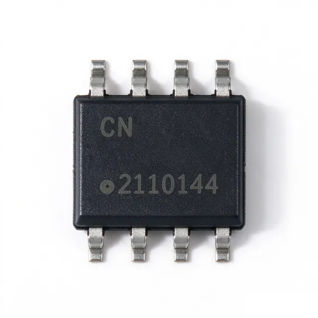
The Microchip Technology ATECC608B-SSHDA-T is a member of the CryptoAuthentication™ family of high-security cryptographic devices that combine world-class hardware-based key storage with hardware cryptographic accelerators. It is offered in an 8-pin SOIC package with I²C interface, supports ECC-P256 (ECDH and ECDSA), SHA-256, AES-128-GCM, and provides a hardware random number generator (NIST SP 800-22 compliant) plus a monotonic counter. The device integrates 10Kb secure EEPROM for keys, certificates, and data, with built-in tamper resistance including voltage glitch and temperature tamper detection. What is a CryptoAuthentication IC? A CryptoAuthentication IC is a specialized secure element that offloads cryptographic operations from the main microcontroller and protects private keys in hardware-isolated storage. These devices sit at the foundation of the security hierarchy: CryptoAuthentication IC → secure element → hardware root-of-trust → embedded security subsystem. Unlike software-based cryptography, hardware secure elements ensure private keys never leave the silicon, dramatically reducing attack surface for IoT devices, network accessories, and edge nodes where MCU resources are limited but trust is non-negotiable. The ATECC608B features a full ECDH/ECDSA engine operating in approximately 13 ms for sign operations and SHA-256/HMAC hardware acceleration, dramatically reducing cryptographic workload on host MCUs. It supports standard I²C up to 1 Mbps with configurable I²C addresses, an optional single-wire interface (SWI) variant, and operates from 2.0V to 5.5V supply with deep-sleep current as low as <150 nA. Internal EEPROM is locked through one-way fuses, preventing post-deployment firmware or key extraction by physical or remote attacks. Typical applications include Matter/Thread device authentication, secure boot for Linux/Windows IoT edge nodes, AWS IoT multi-account registration, IP protection and firmware anti-cloning, accessory and consumable authentication (medical, industrial, printer cartridges), and TLS 1.2/1.3 mutual authentication offload for resource-constrained MCUs. The device ships with Microchip's CryptoAuthLib, which provides a unified API across the entire CryptoAuthentication family. When designing with the ATECC608B, ensure I²C pull-ups are present (the SOIC version uses standard I²C, not SWI), allocate a dedicated 7-bit I²C address, and provision keys via the Microchip CryptoEvaluation kit during development. The GPIO pin can be used as a power-on reset indicator or wake source. Migration from ATECC608A is software-compatible via CryptoAuthLib. This page synthesizes distributor pricing, drop-in same-package alternatives, and practical design notes not consolidated in the manufacturer datasheet alone.