Motortreiber
Produkte (261)

DRV8806PWPR - 40V 3A Quad Low-Side Motor Driver | TI
The Texas Instruments DRV8806PWPR is a 40 V, 3 A quad-channel low-side driver with integrated SPI and open-load detection, housed in a 16-pin HTSSOP (PWP) package with PowerPAD. It provides four protected low-side DMOS outputs that can deliver up to 2 A continuous per channel (3 A peak) and is primarily intended to drive unipolar stepper motors, DC motors, solenoids, and relays from a single supply rail. A low-side motor driver is a topology where each output transistor pulls the load terminal to ground, while the opposite end of the load remains tied to the supply. In the broader power-management taxonomy, the DRV8806 sits within motor drivers and gate drivers, which themselves belong to the power-management IC family. Compared with full H-bridge drivers, low-side drivers are simpler, cheaper, and easier to parallel, but they require the load to be tied to the supply externally and cannot actively brake by sourcing current into the rail. Key features include four independent DMOS outputs with 200 mOhm RDS(on) typical, integrated freewheeling clamp diodes for inductive loads, configurable overcurrent protection per channel, open-load detection through the SPI interface, thermal shutdown, and undervoltage lockout. The SPI port exposes fault status, control bits, and PWM duty-cycle registers, allowing a host MCU to manage current limiting and diagnose wiring faults without extra analog circuitry. The device operates from 8.2 V to 38 V on VM and is controlled through a 3.3 V-compatible SPI bus. Internal charge-pump-derived gate drive keeps the low-side FETs fully enhanced across the full supply range, while the on-chip current-sense comparator supports PWM current chopping for stepper or solenoid actuation. A fault output pin flags overtemperature, overcurrent, and open-load events to the host. Typical applications include unipolar stepper motor indexing, inkjet and label printer carriage control, solenoid and valve drivers, relay arrays, and low-voltage DC brush motor actuation. The wide 8.2 V to 38 V supply range covers 12 V and 24 V industrial buses, making the part attractive for factory automation boards. When laying out the PCB, solder the exposed PowerPAD to a continuous ground copper pour to keep junction temperature within ratings; without this thermal path the package cannot dissipate the full 3 A per channel. Bypass VM with a 100 nF ceramic plus a 47 uF or larger bulk capacitor placed within 5 mm of the supply pin to suppress the high di/dt transients that occur during PWM chopping. This page consolidates distributor pricing, drop-in alternatives, and design notes that go beyond the manufacturer datasheet to help engineers shorten their selection and qualification cycle.

DRV8814PWPR - 47V 2.5A Dual Brushed DC Motor Driver | TI
The Texas Instruments DRV8814PWPR is a 47-V, 2.5-A dual brushed DC motor driver with integrated inrush protection, housed in a 28-pin HTSSOP (PWP) package with PowerPAD. It operates from an 8 V to 45 V supply and provides two independent H-bridge channels that can each deliver up to 2.5 A of continuous drive current at 24 V and TA = 25 °C, making it well-suited to printers, scanners, robotic actuators, and other automated equipment. A dual H-bridge motor driver is a power IC that integrates four power MOSFET switches and their control logic into one package so a microcontroller can command direction, brake, coast, and PWM-based current regulation on two DC motors (or one bipolar stepper) from a single supply rail. These devices sit in the broader hierarchy of motor control IC -> motion control -> power management, and the DRV8814 family is part of TI's brushed-DC driver portfolio distinguished by integrated current-sense and parallel interface control. Key features of the DRV8814PWPR include four-level winding current control, multiple decay modes (slow decay, fast decay, and mixed decay), a PHASE/EN parallel interface for direction and enable, an internal inrush current limiter that protects the supply rail at startup, and built-in protection features including overcurrent protection (OCP), thermal shutdown (TSD), undervoltage lockout (UVLO), and fault-current reporting via the FLT pin. The HTSSOP-28 PowerPAD package delivers a low thermal resistance of approximately 31 °C/W (junction-to-case), enabling continuous 2.5 A operation with moderate PCB copper area. The parallel control scheme allows four discrete control inputs, simplifying host-firmware logic and reducing MCU timer overhead compared to PWM-only stepper interfaces. The DRV8814PWPR is typically used in printers, scanners, robotic actuators, automated teller machines, textile machinery, and office automation. Its 45-V absolute-maximum supply tolerance also makes it compatible with 24-V and 36-V industrial bus rails. The DRV8841 and DRV8843 are related TI parts but use different interfaces and are not drop-in compatible. This page synthesizes distributor pricing, drop-in same-package alternatives, parametric tables, and practical design notes not consolidated on the manufacturer product page.
DRV8816PWP - 40V Dual Half-H Bridge Motor Driver | Texas Instruments
The Texas Instruments DRV8816PWP is a 40-V, dual 1/2-H-bridge DMOS motor driver that integrates two independent half-H-bridge output stages into a single 16-pin HTSSOP (PWP) package with PowerPAD. Each output stage uses N-channel power MOSFETs configured as a half-H bridge, and a simple INx/ENx interface allows easy connection to a host controller for brushed DC motors, stepper motor windings, solenoids, relays, and other inductive loads. The device accepts supply voltages from 8 V to 38 V and can deliver up to 2.8 A peak per output, making it a flexible power stage for medium-current motion and actuation subsystems. Background Knowledge: A 1/2-H-bridge motor driver is a power-management integrated circuit that contains two switching MOSFETs (a high-side and a low-side device) and the gate-drive logic to control them in a push-pull fashion. Two half-H bridges can be combined externally to build a full H-bridge for bidirectional DC motor or bipolar stepper winding control. The DRV8816 family belongs to the broader category of integrated motor drivers, which sit inside the power-management IC hierarchy and replace discrete MOSFET gate-drive circuits to save board area, simplify firmware, and add on-chip current limiting. Key features include built-in shoot-through protection, integrated current-sense feedback for current control loops, undervoltage lockout (UVLO), and thermal shutdown with fault-flag indication. The device operates over a -40 C to +85 C ambient range and is offered in a thermally enhanced HTSSOP-16 (PWP) package with an exposed thermal pad that lowers theta_JA and enables continuous high-current operation with a moderate PCB copper pour. A parallel-interface architecture lets two independent outputs share logic pins without SPI overhead, which simplifies firmware and reduces controller pin count compared to multi-channel serial PMIC interface topologies. Architecturally, the DRV8816 uses DMOS output transistors with low on-resistance, which reduces thermal losses at high peak currents. The integrated charge pump supplies the high-side gate drive, and a programmable blanking time suppresses false current-sense trips caused by diode reverse recovery. This makes the device suitable for fast-switching PWM control up to 200 kHz with predictable current-limit behavior across motor and solenoid loads. Typical applications include brushed DC motor drivers, bipolar stepper motor winding drivers, solenoid and valve drivers, LED string drivers, and generic half-H-bridge actuator stages. Two DRV8816 channels can be wired together externally to form a single full H-bridge for one bipolar stepper motor (single-axis), or two channels can each drive an independent brushed DC motor, solenoid, or relay. The wide 8 V to 38 V supply range covers both 12 V and 24 V industrial bus rails. When designing with the DRV8816PWP, observe the thermal limits: at 2 A per channel continuous with both channels active, dissipation can exceed 2 W and requires the exposed pad to be soldered to a copper pour of at least 1 square inch. Always respect the absolute-maximum supply of 40 V and add a bulk reservoir capacitor near the VM pin to absorb motor back-EMF. This page synthesizes distributor pricing, drop-in alternatives, and practical PCB thermal guidance not found in the manufacturer datasheet alone, giving engineers a single source for sourcing and second-source-equal-cross-reference decisions on the DRV8816 half-H-bridge family.

DRV8818PWPR - 2.5A Bipolar Stepper Motor Driver | TI
The Texas Instruments DRV8818PWPR is a bipolar stepper motor driver with integrated current regulation and microstepping indexer, capable of driving up to 2.5 A per winding. It operates from a supply voltage range of 8 V to 35 V and is housed in a 28-pin HTSSOP (PWP) package with an exposed thermal pad (PowerPAD). The device integrates two H-bridge drivers and a microstepping indexer that supports up to 1/8-step operation, making it suitable for printers, scanners, textile machines, and other automated equipment. A stepper motor driver is a power management IC that translates step and direction signals into the precise current sequences needed to rotate a stepper motor. It typically includes H-bridge output stages, current sensing, and protection features. The DRV8818 belongs to the motor driver category, which is part of the broader power management IC family. It uses a STEP/DIR interface, simplifying the connection to a microcontroller or motion controller. Key features of the DRV8818PWPR include a low 0.37 Ω (HS + LS) MOSFET on-resistance at 25°C, which minimizes power dissipation and improves efficiency. The device supports programmable mixed decay, blanking time, and off time, allowing designers to optimize current regulation for different motor types and operating conditions. It also provides a separate logic supply voltage (VCC) for the digital interface, enabling operation with 3.3 V or 5 V logic while the motor supply can be up to 35 V. The DRV8818 uses a current-regulation architecture with a built-in indexer that generates the microstepping waveforms. The device includes protection features such as overcurrent, overtemperature, and undervoltage lockout. The low on-resistance and high current capability make it suitable for applications requiring smooth motion and low heat generation. Typical applications include 3D printers, office automation equipment, vending machines, and industrial automation. The device's wide supply range and robust output stage allow it to drive a variety of bipolar stepper motors. The HTSSOP-28 package with PowerPAD provides excellent thermal performance, enabling continuous operation at high currents with proper PCB layout. When designing with the DRV8818, ensure adequate decoupling on the motor supply and logic supply pins. The exposed thermal pad must be soldered to a copper plane for heat dissipation. The STEP/DIR inputs should be filtered to avoid noise-induced false steps.
DRV8825PWPR - 45V 2.5A Stepper Motor Driver | TI
The Texas Instruments DRV8825PWPR is a bipolar stepper motor driver with integrated current regulation and 1/32 microstepping, delivering up to 2.5A output current (with proper thermal design) in a 28-pin HTSSOP (PWP) package. It operates from a supply voltage of 8.2V to 45V, making it suitable for a wide range of industrial and consumer motion control applications. A stepper motor driver is a power management IC that translates step and direction signals into the precise current sequences needed to drive a bipolar stepper motor. It integrates two H-bridges and a microstepping indexer, simplifying the interface between a microcontroller and the motor. The DRV8825 belongs to the motor driver category, which is part of the broader power management IC family. Key features include 1/32 microstepping, which provides smooth motion and reduced noise, and current regulation that maintains constant torque regardless of motor speed. The device also includes protection features such as overcurrent, overtemperature, and undervoltage lockout, ensuring reliable operation in demanding environments. The nFAULT pin provides fault indication to the host controller. The DRV8825 uses a power MOSFET architecture with low on-resistance, minimizing power dissipation and improving efficiency. The microstepping indexer generates the necessary current waveforms, reducing the computational load on the microcontroller. The device supports both step/direction and phase/enable interfaces, offering flexibility in system design. Typical applications include 3D printers, CNC machines, robotics, and automated equipment such as printers and scanners. The wide voltage range and high current capability make it ideal for driving NEMA 17 and NEMA 23 stepper motors. The HTSSOP package with exposed thermal pad facilitates heat dissipation, enabling continuous operation at moderate currents. When designing with the DRV8825, ensure adequate PCB copper area for thermal management, especially at currents above 1.5A. Place the sense resistors close to the device and use proper decoupling capacitors on the VM pin to minimize voltage spikes.
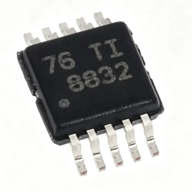
DRV8832DGQR - 1A H-Bridge Motor Driver 6.8V | Texas Instruments
The Texas Instruments DRV8832DGQR is a 1 A low-voltage H-bridge motor driver with integrated voltage regulation, operating from a 2.75 V to 6.8 V supply and housed in a 10-pin HVSSOP (DGQ) package with exposed thermal pad. An H-bridge motor driver is a power management IC that controls the direction and speed of a DC motor by selectively energizing four power transistors arranged in an H configuration. It sits between a low-power microcontroller and the motor winding, translating logic-level control signals into high-current drive. Within the semiconductor hierarchy, the DRV8832 belongs to the motor driver family under power management ICs, complementary to voltage regulators and gate drivers in motion-control signal chains. Key features include a high-efficiency power stage built from N-channel and P-channel power MOSFETs with low RDS(on), achieving up to 97% efficiency. The integrated voltage-regulation loop maintains a stable effective motor voltage, improving speed regulation directly from a discharging battery. A current-limit function regulates winding current during motor start-up or stall, and a dedicated nFAULT output pin signals fault conditions to a host processor. Technically, the DRV8832 provides one H-bridge controlled by IN1 and IN2 logic inputs, capable of driving one brushed DC motor, one winding of a stepper motor, or other loads such as solenoids. Protection includes thermal shutdown and undervoltage lockout (UVLO) for robust field operation. The tiny 3 mm x 3 mm package supports compact, battery-powered layouts, and the device is offered in eco-friendly RoHS-compliant construction without Sb/Br. Typical applications include battery-powered toys, printers, and other portable motion-control products, where its wide 2.75 V to 6.8 V supply range tracks battery discharge directly, plus small-appliance actuators and solenoid drivers. When designing with this device, provide adequate PCB copper under the exposed thermal pad for heat dissipation at sustained 1 A loads, and place decoupling capacitors close to the supply pins to minimize voltage transients during PWM switching. This page synthesizes distributor pricing context, verified drop-in alternatives, comparison data, and practical design notes not found in the manufacturer datasheet alone.

DRV8832DRCR - 6.8V 1A H-Bridge Motor Driver | Texas Instruments
The Texas Instruments DRV8832DRCR is a 6.8V, 1A H-bridge brushed DC motor driver IC with integrated current regulation, housed in a 3-mm x 3-mm 10-pin VSON (DRC) package. It integrates the power MOSFETs, gate drive, current-limit circuitry, and fault reporting needed to drive one brushed DC motor or one winding of a stepper motor from a single low-voltage supply. An H-bridge motor driver is a power management IC that uses four switching transistors arranged in an H configuration to reverse the polarity of the voltage applied to a motor, enabling forward, reverse, brake, and coast (hi-Z) operation. Within the system hierarchy, motor drivers sit between a host controller (MCU or logic) and the motor itself, translating low-current logic commands into high-current motor drive while providing protection features such as current limiting, undervoltage lockout, and thermal shutdown. Key features include a wide operating supply range for battery-powered designs, a fixed off-time PWM current-regulation scheme that limits motor current during start-up or stall conditions, a low-power sleep mode that reduces supply current to conserve battery life, and an nFAULT output pin that signals fault conditions to a host processor. The integrated MOSFETs deliver up to 1A of continuous output current without external discrete transistors. The DRV8832 architecture uses internal gate drive and voltage regulation so that only the motor supply and logic inputs are required externally - no external bootstrap components or gate-drive circuitry are needed. The internal current-limit regulation repeatedly disables and re-enables the bridge at a fixed off-time when the set current threshold is exceeded, holding motor torque under control during stall or acceleration events and protecting both the IC and the motor windings. Typical applications include battery-powered toys, printers, and other low-voltage or battery-powered motion control products such as small actuators, camera lenses, locks, and consumer robotics. The low minimum supply voltage suits single-cell or dual-cell battery stacks, and the tiny 3x3 mm footprint suits space-constrained mechanisms in printers and portable devices. A key design consideration is thermal management: at high load currents the VSON-10 package relies on its exposed pad soldered to a copper pour on the PCB to dissipate heat. Verify that the continuous motor current and the on-resistance of the internal MOSFETs keep junction temperature within limits over the full ambient range. This page synthesizes verified distributor data, TI product information, drop-in alternative analysis, and practical design notes not found in the manufacturer datasheet, providing an engineering-ready reference for the DRV8832DRCR.

DRV8837DSGR - 12V 1.8A H-Bridge Motor Driver | Texas Instruments
The Texas Instruments DRV8837DSGR is a 12 V, 1.8 A low-voltage H-bridge motor driver with PWM control, housed in an 8-pin WSON (DSG) package. It is designed to drive a brushed DC motor, one winding of a stepper motor, solenoids, or other bidirectional loads from battery-powered systems. Its integrated interface uses IN1 and IN2 inputs for direction and PWM control, while internal shutdown functions provide overcurrent, short-circuit, undervoltage-lockout, and overtemperature protection. An H-bridge motor driver is a power-management semiconductor that uses four MOSFET output switches to reverse current through a load and regulate its speed. The DRV8837 belongs to the motor-driver and power-management IC hierarchy, combining a control input stage, N-channel power MOSFETs, an H-bridge power stage, and integrated protection in one compact device. This makes it suitable for compact motion systems where a discrete MOSFET bridge would require more board area and additional protection circuitry. The DRV8837DSGR provides a maximum drive current of 1.8 A and is identified as a 12 V H-bridge motor driver. Its PWM interface supports speed control, while the IN1-IN2 logic determines drive direction. Internal shutdown functions are specified for overcurrent protection, short-circuit protection, undervoltage lockout, and overtemperature conditions. The device is intended for low-voltage or battery-powered motion-control applications such as cameras, consumer products, toys, and other compact motorized equipment. The WSON (DSG) package has 8 pins and is specified for surface mounting. Its compact package helps reduce PCB footprint, but thermal performance and exposed-pad layout remain important at sustained high motor current. The motor and wiring environment can introduce electrical noise, inductive transients, and large current loops, so power-loop layout, grounding, bulk capacitance, and protection must be designed together. The manufacturer product page and distributor records are the primary sources for current package, ordering, and lifecycle information. Typical applications include small camera positioning mechanisms, battery-operated toys, consumer appliances, compact fan or pump controls, solenoid actuation, and low-voltage stepper-motor winding drives. For these applications, the DRV8837 provides bidirectional control and integrated fault handling, reducing the number of external power transistors and support components. The main design trade-off is that the motor's supply voltage, stall current, wiring inductance, and thermal conditions must remain within the device's verified operating limits. This page combines verified Texas Instruments product information, distributor search results, package details, application guidance, and a strict drop-in alternative review. The DRV8837DSGR is listed with an 8-pin WSON DSG package and an operating temperature range of -40 to 85 in the verified product-page snippet. Confirm the complete electrical limits, pin functions, exposed-pad requirements, and protection behavior against the current manufacturer datasheet before releasing a production design.

DRV8847PWPR - 18V 2A Dual H-Bridge Motor Driver | Texas Instruments
The Texas Instruments DRV8847PWPR is an 18-V, 2-A dual H-bridge motor driver with integrated power MOSFETs, current regulation, and independent half-bridge control, housed in a 16-pin HTSSOP (PWP) package with PowerPAD exposed thermal pad. It is designed to drive two dc brushed motors, a bipolar stepper motor, relays, solenoids, or other mechatronic loads from a single 0 to 11-V (absolute max 18-V) power supply. An H-bridge motor driver is a type of brushed dc or stepper motor driver that uses four switching elements arranged in an H configuration to apply voltage to a motor winding in either polarity. The dual H-bridge architecture used in the DRV8847 sits within the broader motor driver hierarchy: motor driver -> H-bridge -> half-bridge -> power management IC -> semiconductor. Independent half-bridge control allows each of the four low-side and high-side FETs to be addressed separately, enabling advanced commutation schemes, current-mode regulation, and parallel MOSFET control when higher drive current is required. Key differentiating specifications include a low 7.5-mA (typical) quiescent current, integrated current-sense with chopping regulation at 5 A peak per H-bridge, built-in 1.5-A continuous output current per H-bridge (with proper PCB thermal design), independent INx/ENx logic interface per half-bridge, automatic dead-time generation, and overtemperature/overcurrent/undervoltage protection. The integrated protection is proprietary to the DRV8847 and removes several discrete parts that a discrete H-bridge design would need. Technically, the device uses N-channel power MOSFETs in each half-bridge with internal charge pump to drive the high-side gates, allowing 100% duty cycle operation. The internal current-shunt amplifier with external reference (VREF) supports both fixed off-time and PWM current chopping, enabling precise torque control in stepper or brushed-dc applications. Typical applications include industrial automation (small stepper indexers, valve actuators, ePOS printers), home appliances (small pumps, fans, latches, dispenser valves), robotics and toys (low-voltage brushed dc gearmotors), and office equipment (paper feeders, scanners). The HTSSOP-16 PowerPAD provides a low thermal resistance path suitable for sustained 1.5 A per bridge operation when the exposed pad is soldered to a sufficient copper area. Design consideration: at full-load conditions the DRV8847 dissipates substantial heat (estimated P_diss = (V_supply - V_motor) * I_load per H-bridge), so always follow the datasheet thermal layout guidance with PowerPAD soldered to at least 1 oz copper pour. For applications above 1.5 A continuous per bridge, derate the supply voltage or provide forced-air cooling. This page synthesizes distributor pricing, drop-in same-package alternatives, and practical design notes not found in the manufacturer datasheet alone.

DRV8872DDAR - 3.6A 45V Brushed DC Motor Driver | Texas Instruments
The Texas Instruments DRV8872DDAR is a 45-V, 3.6-A peak H-bridge brushed DC motor driver housed in an 8-pin HSOP PowerPAD package with an exposed thermal pad for heat dissipation. The device integrates four N-channel MOSFETs and supports bidirectional drive with up to 3.6-A peak current, operating from a 6.5-V to 45-V supply, with a typical R_DS(on) of 565 mΩ per high-side + low-side FET. A brushed-DC motor driver is an integrated power IC that sits between a low-voltage logic controller (MCU, PLC, or PWM source) and a brushed DC motor. It accepts logic inputs (IN1/IN2 or PWM) and converts them into high-current H-bridge outputs capable of sourcing or sinking motor current. The DRV8872 belongs to TI's brushed motor driver portfolio and combines the H-bridge, current-sense amplifier, and protection logic in a single package, eliminating dozens of discrete components and shrinking PCB area. Key features include integrated current regulation via an external sense resistor, automatic fault recovery, two open-drain fault outputs (nFAULT and nSLEEP), a 100% duty-cycle capable drive architecture, and a sleep mode activated by dual-low inputs for low quiescent current. The HSOP-8 PowerPAD package keeps the part's footprint identical to a standard SO-8 while enabling up to 3.6 A peak motor drive, and the thermal pad reduces θJA so the driver can deliver higher continuous RMS current without a separate heatsink. Typical applications include brushed DC motors in printers, appliances, industrial machinery, vending machines, HVAC damper controls, and low-power pumps. The integrated current regulation lets engineers set a precise trip threshold with one external resistor, simplifying closed-loop torque limiting versus discrete FET designs. When designing with the DRV8872DDAR, ensure a low-ESR 100-nF bypass capacitor sits within 5 mm of VM, plus a bulk capacitor rated for the peak motor inrush (typically 10 µF or more); the exposed pad must be soldered to a copper pour of at least 1 cm² to achieve rated thermal performance. This page combines manufacturer specifications, distributor pricing, and same-package drop-in alternatives that go beyond the basic datasheet content.

DRV8873HPWPR - 40V 10A H-Bridge Motor Driver | Texas Instruments
The Texas Instruments DRV8873HPWPR is a 40-V, 10-A peak H-bridge motor driver with integrated current sensing and current-sense feedback, housed in a 24-pin HTSSOP (PWP) package with PowerPAD exposed thermal pad. It drives brushed DC motors bi-directionally via four internal N-channel MOSFETs, accepts a single 4.5-V to 38-V supply, and supports a PH/EN or PWM interface through two logic inputs. An H-bridge motor driver is an integrated power stage that uses four switching transistors arranged in an H topology to drive a DC motor forward or reverse from a single supply rail. It sits below the brushed-DC motor in the system hierarchy, fed by a DC bus and commanded by a microcontroller. Compared with discrete MOSFET half-bridges, an integrated H-bridge shrinks board area, adds dead-time control, and provides on-chip current sensing. Key specifications include 10-A peak / 3.5-A continuous output current (with proper PCB thermal design), 4.5-V to 38-V operating supply, integrated current sensing with proportional output on the IPROPI pin, and a low RDS(on) of approximately 200 mOhm per HS+LS FET. The device supports both hardware (HW) PH/EN mode and PWM mode through MODE pin strapping. Protection features include VM undervoltage lockout, overcurrent protection (OCP), thermal shutdown (TSD), and automatic fault recovery. Smart-tune and integrated current regulation reduce BOM count by eliminating external sense resistors. The DRV8873 architecture combines four N-channel power FETs, charge-pump gate drivers, a current-shunt amplifier, and a small analog state machine in a single monolithic die. The IPROPI output delivers a ground-referenced analog voltage proportional to motor current, eliminating the need for a high-side shunt amplifier. This architecture enables closed-loop torque control without an external sense resistor and allows cycle-by-cycle current limiting. Typical applications include industrial brushed-DC motor drives, robotics, small appliances, e-bike and e-scooter traction motors, home automation actuators, and 3D-printer extruders. The wide 4.5-V to 38-V input range comfortably supports 12-V and 24-V industrial buses as well as 6-cell Li-ion battery packs up to 25.2 V nominal. When designing with the DRV8873, ensure the PowerPAD is soldered to at least 200 mm² of copper for thermal performance above 2 A continuous. Add 0.1-µF and 10-µF bypass capacitors close to VM and to the charge-pump CP pin. Use MODE pin strapping to choose PH/EN (hardware) or PWM interface before first power-up. This page synthesizes distributor pricing, AEC-Q100 alternatives, drop-in compatibility notes, and practical PCB-thermal design guidance not consolidated in the manufacturer datasheet.
DRV8873HPWPRQ1 - Automotive 38V H-Bridge Motor Driver | TI
The Texas Instruments DRV8873HPWPRQ1 is an automotive-grade, 38-V, 10-A peak integrated H-bridge motor driver with current sensing and current sense feedback, housed in a 24-pin HTSSOP (PWP) PowerPAD package. It is designed for driving brushed DC motors in automotive applications, supporting a wide 4.5-V to 38-V supply range and bi-directional drive with up to 10-A peak current through four integrated N-channel MOSFETs. The DRV8873-Q1 device adds integrated current sensing that eliminates external shunt resistors, with proportional current output on the IPROPI pin for closed-loop torque control. An H-bridge motor driver is an integrated power stage built from four MOSFETs in an H-Bridge topology, which allows current to flow through the load (motor winding) in either direction by selectively activating diagonal half-bridges. Modern integrated H-bridge ICs such as the DRV8873-Q1 combine the power stage, gate drivers, protection circuitry, and (increasingly) current sensing into a single thermally-enhanced package, falling into the product hierarchy: H-bridge motor driver -> motor driver -> motor / motion / ignition controller -> power management IC -> semiconductor. This integration reduces BOM count, PCB area, and design complexity compared to discrete MOSFET-based bridges. Key features of the DRV8873HPWPRQ1 include a low 0.13-A typical quiescent current (logic version) or hardwired (HW) interface option, integrated current sensing with proportional output, PH/EN or PWM control interface for flexible MCU interfacing, and comprehensive protection features including undervoltage lockout (UVLO), overcurrent protection (OCP), thermal shutdown (TSD), and automatic fault recovery. The device supports both the HW (hardwired) logic variant (this part) and a separate logic-variant counterpart, allowing designers to choose between simple GPIO control and full PWM/microstepping flexibility. The DRV8873HPWPRQ1 uses an N-channel MOSFET H-bridge with charge-pump gate drive for the high-side FETs, ensuring low Rds(on) and high efficiency. Integrated current sensing uses the on-resistance of the low-side FETs rather than an external shunt, which reduces power dissipation and PCB footprint while still providing IPROPI output accurate enough for stall detection and load monitoring. The HTSSOP-24 PowerPAD package provides a low 32-40 degree C/W junction-to-ambient thermal resistance, allowing sustained high-current operation with proper copper thermal relief. Typical applications include automotive brushed DC motors such as HVAC blowers, fuel pumps, water pumps, window lifters, seat adjusters, mirror adjusters, and various body electronics actuators. The integrated current sensing makes the part especially attractive for stall detection and load-based diagnostics required for functional safety (ASIL) aware systems. When designing with this device, ensure adequate copper thermal relief on the PowerPAD to keep junction temperature within limits. Add a 100-nF bypass capacitor on VM as close to the IC as possible, and use the IPROPI resistor to set the current-limit threshold. The HW interface simplifies design when only direction and enable control are needed. This page synthesizes distributor pricing, AEC-Q100 qualification status, pin-compatible alternatives, and practical design notes not found in the manufacturer datasheet alone.

DRV8873QPWPRQ1 - 40V 10A H-Bridge Motor Driver | TI
The Texas Instruments DRV8873QPWPRQ1 is an automotive-grade, 40V, 10A H-bridge motor driver with integrated current sensing, housed in a 24-pin HTSSOP (PWP) PowerPAD package. It operates from a single supply of 4.5V to 38V and is AEC-Q100 qualified for harsh automotive environments. A brushed DC motor driver is a power management IC that controls direction and speed of motors by switching four N-channel MOSFETs in an H-bridge configuration. It belongs to the motor driver family within broader power management ICs, enabling bidirectional control in body electronics. Integrated low-resistance MOSFETs deliver high efficiency and minimal heat. Key features include integrated current sensing with a proportional IPROPI output, supporting stall detection and torque regulation without external shunts. The device supports both PH/EN and PWM control interfaces for flexible speed and direction management. Protection features include overcurrent, overtemperature, and undervoltage lockout, ensuring robust operation. Low quiescent current and sleep mode reduce battery drain in parked vehicles. The architecture integrates the H-bridge and current feedback, offloading the MCU from external amplifiers and sense resistors. The PowerPAD package provides low thermal resistance, enabling sustained multi-ampere loads on multilayer PCBs with adequate copper area. This simplifies system design and reduces BOM cost. Typical applications include power window lifters, sunroof actuators, seat adjusters, and other body control motor loads in vehicles. The wide input range also supports 12V and 24V automotive systems. Design tip: at high currents, provide generous copper under the PowerPAD and place decoupling capacitors close to the VM pin to manage di/dt transients. This page synthesizes distributor pricing, drop-in alternatives, and practical design notes not found in the manufacturer datasheet.

DRV8876PWPT - 40V 3.5A H-Bridge Motor Driver | TI
The Texas Instruments DRV8876PWPT is a 40-V, 3.5-A H-bridge motor driver with integrated current sensing and current-sense feedback, designed for driving one bidirectional brushed DC motor or two unidirectional brushed DC motors. It operates from a 4.5-V to 37-V supply voltage range and is available in a 16-pin HTSSOP (PWP) package. The device integrates an N-channel H-bridge, charge pump regulator, current sensing and regulation, and protection features, making it a compact and efficient solution for a wide range of motor control applications. An H-bridge motor driver is a power management IC that controls the direction and speed of a brushed DC motor by selectively turning on four transistors in an H configuration. The DRV8876 integrates the H-bridge, gate drivers, and protection circuitry into a single package, simplifying PCB design and reducing component count. It is part of the DRV887x family of brushed DC motor drivers, which are known for their flexibility and robustness. Key features include a 4.5-V to 37-V operating supply voltage, 3.5-A peak drive current, integrated current sensing with adjustable current regulation, and a low-power sleep mode. The device also provides overcurrent, overtemperature, and undervoltage lockout protection. The integrated current sense amplifier outputs a voltage proportional to the motor current, enabling precise torque control without external sense resistors. The DRV8876 uses an N-channel H-bridge architecture with a charge pump to drive the high-side FETs, achieving low RDS(on) and high efficiency. The current regulation feature allows the motor current to be limited to a programmable level, protecting the motor and power supply. The device is designed for industrial and consumer applications, including printers, robotics, and home appliances. Typical applications include brushed DC motor control in printers, robotics, and industrial automation. The wide supply voltage range and integrated protection make it suitable for battery-powered and industrial systems. The HTSSOP package with exposed thermal pad aids in heat dissipation, enabling reliable operation at high currents. When designing with the DRV8876, ensure adequate PCB copper area for thermal management, and place the charge pump capacitor close to the CP1 and CP2 pins. The current sense resistor should be placed near the ISEN pin to minimize noise. Proper decoupling on the VM pin is essential for stable operation.
DRV8886ATPWP - 37V 2A Bipolar Stepper Driver | Texas Instruments
The Texas Instruments DRV8886ATPWP is a 37-V, 2-A bipolar stepper motor driver with integrated current sensing and AutoTune (smart tune) technology, housed in a 24-pin HTSSOP (PWP) PowerPAD package. It integrates two N-channel power MOSFET H-bridge drivers, a microstepping indexer, and on-chip current-sense resistors, capable of driving up to 2-A full-scale or 1.4-A rms output current at 24 V and TA = 25°C (dependent on PCB design). The device supports STEP/DIR control up to 1/16 microstep resolution, and operates from a motor supply (VM) of 8 V to 37 V with a separate 3 V to 5.5 V logic supply (VCC). A stepper motor driver is a power-management IC that converts low-power STEP and DIR logic signals from a microcontroller into the high-current phase currents required to commutate a two-phase bipolar stepper motor. It sits in the system hierarchy between the motion controller (often a microcontroller, FPGA, or dedicated motion MCU) and the mechanical motor, providing regulated current through each winding using an H-bridge topology with PWM current chopping. The DRV8886ATPWP belongs to the brushless-DC/stepper motor driver subcategory of power management ICs, integrating MOSFETs, gate drivers, and a microstepping indexer so the host only needs to provide step pulses. Key features include a low 550 mΩ HS+LS on-resistance, integrated current sensing that eliminates external sense resistors, AutoTune (smart tune) technology that dynamically adapts decay mode to motor operating region, internal 3.3-V reference, stall detection (when used with AutoTune), and a low 20-µA sleep current. Programmable features include configurable decay modes (smart tune, mixed, slow, fast), 1 to 1/16 microstepping, torque DAC, and adjustable blanking/sleep timing via serial interface or external resistor. Architecturally, the device combines a charge-pump gate driver, dual H-bridges built from N-channel MOSFETs, an internal current-sense amplifier per phase, and a state machine that handles microstepping commutation. This integration removes external sense resistors and allows the system MCU to focus on motion profiles rather than real-time current control. Typical applications include 3D printers, automated door locks, point-of-sale (POS) printers, CCTV camera pan/tilt/zoom, and office automation equipment. For example, in a 3D printer extruder or bed-feeder axis, the DRV8886ATPWP delivers smooth microstep motion with AutoTune handling back-EMF-induced current distortion without firmware intervention. When designing with this part, ensure the PowerPAD is soldered to a copper pour of at least 1 in² to achieve the rated 1.4-A rms continuous current; the package's thermal performance is PCB-dependent. Use a 0.1-µF VCC bypass capacitor close to the IC and follow the datasheet ground/power layout recommendations to keep digital switching noise out of the sense amplifier. This page synthesizes verified distributor pricing, same-brand and cross-brand drop-in alternatives, application notes, and practical design guidance not consolidated on a single manufacturer or distributor page, giving engineers a one-stop decision resource for selecting and implementing the DRV8886ATPWP.
DRV8886ATPWPR - 37V 2A Stepper Driver w/ AutoTune | Texas Instruments
The Texas Instruments DRV8886ATPWPR is a 37-V, 2-A bipolar stepper motor driver with integrated current sensing and AutoTune (smart-tune) technology, housed in a 24-pin HTSSOP (PWP) package with PowerPAD exposed thermal pad. Headline parameters are 2 A full-scale output current (1.4 A rms at 24 V, TA = 25 °C, PCB-dependent), 1/16 microstepping indexer, and 8 to 37 V operating supply. The DRV8886AT is part of TI's DRV888x family for industrial and consumer end equipment. A stepper motor driver is a type of brushed DC motor controller that sequences current through two phase windings to produce precise discrete angular steps. Within the broader taxonomy, stepper drivers are a subset of motor drivers / motion controllers, which themselves belong to power management ICs and discrete semiconductor driver stages. The DRV8886AT integrates two N-channel power MOSFET H-bridges, a microstepping indexer, and current-sense resistors on-chip, eliminating the bulk external sense resistors required by older stepper designs. Key features include integrated current sensing (no external sense resistors), AutoTune adaptive decay that automatically selects between slow/mixed/fast decay modes per cycle, 1/16 microstepping for smooth low-vibration motion, internal 3.3 V reference for logic-level inputs, and comprehensive protection: overcurrent (OCP), overtemperature (TSD), undervoltage lockout (UVLO), and open-load detection. STEP/DIR interface simplifies connection to MCUs and FPGAs. Architecturally, the device uses two synchronous N-channel H-bridges with low RDS(on) FETs driven from a single VM supply. The integrated current-sense amplifier feeds an internal PWM current-chopper that regulates each phase current at the IREF-programmed value. AutoTune dynamically tunes the decay mode to the motor's back-EMF, reducing audible noise and ripple torque versus fixed-decay designs. Typical applications include 3D printers, CNC routers, textile and sewing machines, point-of-sale (POS) printers, video surveillance PTZ cameras, factory automation small stepper axes, and office automation equipment such as document scanners and label printers. Any 24-V-class bipolar stepper up to NEMA 17 size is a natural fit. When designing with the DRV8886ATPWPR, ensure adequate PCB copper under the exposed PowerPAD for thermal dissipation - at 1.4 A rms the chip dissipates roughly 1 W and needs the thermal pad soldered to at least 1 oz copper pour. Decouple VM with a 100 nF ceramic close to the pins plus a bulk 47 µF electrolytic. Use the Sleep (nSLEEP) pin for idle current reduction. This page synthesizes distributor pricing, same-brand and cross-brand drop-in alternatives, and practical thermal/PCB design notes not consolidated in the manufacturer datasheet.
DRV8886PWPR - 37V 2A Bipolar Stepper Driver HTSSOP-24 | TI
The Texas Instruments DRV8886PWPR is a 37-V, 2-A bipolar stepper motor driver with integrated current sensing and 1/16 microstepping, housed in a 24-pin HTSSOP (PWP) PowerPAD package with exposed thermal pad. It integrates two N-channel power MOSFET H-bridge drivers, a microstepping indexer, and internal current-sense resistors, eliminating the need for external sense resistors in most designs. A stepper motor driver is an integrated power IC that converts low-voltage logic step/direction signals into high-current, sequenced phase outputs capable of driving a two-phase bipolar stepper motor. Within the broader taxonomy, the DRV8886PWPR belongs to the motor driver family (full-bridge + indexer + current sense) inside the power management semiconductor category, complementary to brushed DC and three-phase BLDC drivers like the DRV887x and DRV832x series. Key specifications include 8-V to 37-V operating supply range, 2-A full-scale / 1.4-A rms phase current, 550 mOhm HS+LS on-resistance, 8 configurable decay modes (including TI's Smart Tune dynamic decay), 1.4 uA typical sleep current, and an internal indexer supporting up to 1/16 microstepping. STEP/DIR control with one logic input per phase simplifies MCU interfacing. The device uses an internal current-sense architecture with built-in sense FETs and a configurable chopping frequency up to 50 kHz, eliminating the power-loss and PCB-area penalty of external shunt resistors. Onboard protection includes VM undervoltage lockout (UVLO), charge-pump undervoltage, overcurrent protection (OCP), thermal shutdown (TSD), open-load detection, and fault indication on the nFAULT pin. The HTSSOP-24 PowerPAD package provides a low theta_JC of approximately 4 C/W for efficient heat extraction. Typical applications include 3D printers, CCTV pan-tilt-zoom (PTZ) cameras, office automation equipment (printers, scanners, copiers), textile and sewing machines, factory automation, and any 24-V nominal bipolar stepper system up to 2 A per phase. The 1/16 microstepping produces smooth motion profiles critical for precision positioning. When designing with the DRV8886PWPR, ensure the exposed PowerPAD is soldered to a copper pour of at least 1 square inch to keep junction temperature within safe limits. The DRV8886PWPR is pin-compatible with the lower-current DRV8884 (1.0 A) and DRV8886AT (automotive grade), enabling scalable hardware platforms. This page synthesizes distributor pricing, drop-in alternatives, comparison data, and practical design notes beyond what is found in the manufacturer datasheet alone, helping engineers select and qualify the right stepper driver quickly.

DRV8889-Q1 - 45V 1.5A Automotive Stepper Driver | Texas Instruments
The Texas Instruments DRV8889-Q1 is an integrated automotive bipolar stepper motor driver with up to 45 V operating voltage, 1.5 A full-scale output current, and 1/256 microstepping resolution, housed in a 24-pin HTSSOP (PWP) package with PowerPAD. It integrates dual N-channel power MOSFET H-bridges, integrated current sensing and regulation circuitry, and an internal microstepping indexer. A stepper motor driver is a power management IC that converts digital step and direction commands, or SPI register writes, into phased coil currents that rotate a stepper motor in precise increments. Within the power management hierarchy, it sits below the general motor-driver category and above discrete H-bridge MOSFET solutions, combining control logic and power stage in a single semiconductor package. Key differentiating features include the smart tune decay technology, which automatically selects the decay mode to minimize audible ripple and improve current regulation accuracy, and an advanced stall detection algorithm that infers rotor position loss without external sensors. Integrated current sensing eliminates external sense resistors, reducing BOM cost and PCB area, while integrated current regulation protects the MOSFET bridges from overcurrent. Architecturally, the DRV8889-Q1 combines a microstepping indexer, two full H-bridges with internal current-sense circuitry, and protection features such as thermal shutdown, undervoltage lockout, and overcurrent protection. Control is available through a serial SPI interface for full register access or a legacy Step/Direction interface for simple motion controllers, allowing the same silicon to serve both MCU-driven and ASIC-driven designs. Typical applications include automotive headlamp leveling actuators, HVAC damper and air-flap actuators, throttle and EGR valve positioners, and headlight beam-rotation modules. In each case the 1/256 microstepping delivers smooth, quiet motion while stall detection provides diagnostics required for functional-safety monitoring in automotive ECUs. A key design consideration is thermal: with two integrated H-bridges driving 1.5 A full-scale current, the PowerPAD on the HTSSOP-24 package must be soldered to a substantial copper pour to keep junction temperature within the AEC-Q100 operating range. The AEC-Q100 qualified DRV8889A-Q1 variant is preferred for new automotive designs because it adds configurable open-load detection timing and defaults the H-bridges to disabled after power-up. This page synthesizes verified distributor data, drop-in alternatives including the pin-to-pin compatible NSD8389, and practical design notes not found in the manufacturer datasheet.

FPDB30PH60 - 600V 30A Bridgeless PFC Smart Power Module | onsemi
The onsemi FPDB30PH60 is a PFC SPM 3 (Smart Power Module) that integrates a fully featured, high-performance bridgeless Power Factor Correction input power stage in a single 27-pin DIP module with offset leads (SPMCA-027 package). The module is built around 600 V / 30 A rated IGBTs, and it targets mid-power applications such as air conditioners, white goods, medical power supplies, and industrial converters up to roughly 3 kW. A Power Factor Correction (PFC) smart power module is a co-packaged sub-system that combines the power switching devices (IGBTs and diodes), the high-side and low-side gate drivers, fault protection, and often bootstrap diodes for the high-side supply. Bridgeless PFC eliminates the input diode bridge used in conventional boost PFC, which directly reduces conduction losses and improves overall efficiency at higher power levels. This places the FPDB30PH60 in the functional hierarchy of: smart power module -> IPM (Intelligent Power Module) -> power semiconductor -> power management solution. Key electrical features include a 600 V collector-emitter breakdown voltage, a 30 A continuous IGBT current rating (20 A module rating), an integrated gate drive optimized for low EMI, and on-module protection circuits that include under-voltage lockout (UVLO), over-current protection (OCP), and thermal shutdown interfacing. The 2.5 kV isolation rating supports direct heatsink mounting. The dip-style module with offset leads simplifies PCB layout by separating power leads from signal leads. Internally, the device uses a bridgeless topology in which the AC line current flows through two IGBT/diode pairs rather than a diode bridge plus a boost switch. The integrated gate drive IC is matched to the IGBT characteristics to minimize switching losses and control dv/dt. The SPMC A case (SPMCA-027) provides a screw-mountable base for direct thermal attachment to a chassis-mounted heatsink. Typical applications include air conditioner outdoor units (the part was designed especially for this segment), refrigerator compressor drives, fan and pump motor PFC front ends, medical imaging equipment front-end PFC, and industrial SMPS input stages. The bridgeless architecture makes the device particularly attractive when efficiency targets exceed what a conventional boost PFC + bridge rectifier stage can deliver. When designing with this part, ensure that the heatsink is sized for the worst-case IGBT conduction and switching losses, place a low-ESR electrolytic bulk capacitor on the DC bus, and follow the application guidance for the thermistor interface. Avoid connecting signal ground and power ground at the module - they must meet only at the PCB star ground. This page synthesizes distributor pricing, drop-in alternative cross-references, and application-specific design notes that are not aggregated in the manufacturer's datasheet, providing engineers with a single-decision-source view of the FPDB30PH60.
FS03MR12A6MA1B - 1200V 400A CoolSiC Six-Pack EV Module | Infineon
The Infineon FS03MR12A6MA1B is a 1200 V, 400 A (Tj) CoolSiC Automotive MOSFET six-pack power module in the compact HybridPACK Drive (AG-HYBRIDD-2) chassis-mount package, optimized for (H)EV traction inverters. It integrates six silicon-carbide power MOSFETs in a three-phase bridge topology with low on-state resistance and very high power density. A power module is an integrated assembly of multiple power semiconductor dies, soldered and wire-bonded on a direct-bonded copper (DBC) substrate within an insulated housing, providing gate, DC-link, and phase terminals for inverter power stages. Power modules sit at the top of the power-management hierarchy (MOSFET die -> power module -> traction inverter -> electric drivetrain), combining thermal management, creepage/clearance insulation, and parasitic minimization in one mechanical unit. Key features include 1200 V blocking voltage suited to automotive DC-link voltages, 400 A continuous junction-current capability (800 A pulsed per datasheet Table 3, per Infineon Developer Community guidance), CoolSiC MOSFET technology delivering low switching losses and temperature-stable RDS(on), and the very compact HybridPACK Drive footprint that enables higher power density than comparable IGBT modules. Technically, the module leverages Infineon's CoolSiC Automotive MOSFET 1200 V generation. Silicon carbide's wider bandgap yields reduced switching energy (the datasheet characterizes body-diode reverse-recovery losses Erec versus gate resistance RG at Vr = 600 V, ISD = 400 A, VGS = -5.0/15.0 V), enabling higher switching frequencies, smaller passives, and higher inverter efficiency than silicon IGBT solutions. Gate drive requirements include negative off-state gate voltage (-5 V typ.) and careful common-source inductance management. Typical applications are (H)EV main traction inverters, auxiliary drive inverters, and high-power industrial motor drives where 1200 V class and compact footprint are required. The module pairs with Infineon EiceDRIVER gate drivers and evaluation kits for inverter design-in. Design consideration: cooler design and flow direction must follow Infineon application note AN-HPDPERF-ASSEMBLY, and continuous current must not exceed 400 A per the datasheet limits. This page synthesizes datasheet data, distributor listings, drop-in-family alternatives, and practical design notes not found in the manufacturer datasheet alone.
FS100R12KT4G - 1200V 100A Sixpack IGBT Module | Infineon
The Infineon FS100R12KT4G is a 1200 V, 100 A sixpack (three-phase inverter) IGBT power module in the EconoPACK 3 package, built on fast TRENCHSTOP IGBT4 trench/field-stop technology with Emitter Controlled 4 (EmCon4) freewheeling diodes and an integrated NTC temperature sensor. An IGBT (Insulated Gate Bipolar Transistor) module combines multiple IGBT dies and anti-parallel diodes on a common isolated substrate inside a single molded housing. In the power-conversion hierarchy, the IGBT module sits above discrete transistors and below complete power assemblies, forming the switching stage of motor drives, solar inverters, and UPS systems. A sixpack topology contains six switches, one per branch, which is the standard configuration for three-phase DC-to-AC inversion. Key features include the 1200 V collector-emitter blocking voltage suited to 400 V/690 V-class industrial DC links, a 100 A nominal DC collector current, and a power dissipation rating of 515 W per the DigiKey listing. The trench/field-stop IGBT4 generation delivers reduced saturation voltage and switching losses versus the earlier IGBT3 generation, while the EmCon4 Emitter Controlled diode minimizes reverse-recovery charge, lowering turn-on loss spikes in hard-switched bridges. The module integrates an NTC thermistor for real-time junction-temperature monitoring, enabling overtemperature protection and derating strategies in the inverter controller. Solder-pin connection technology defines the base FS100R12KT4G version, while the FS100R12KT4G_B11 variant uses Infineon PressFIT press-in contacts for solder-free, replaceable assembly. Infineon qualifies the part for industrial applications according to relevant tests of IEC 60747, 60749 and 60068. Typical applications are three-phase motor drives for industrial automation, solar and wind power converters, servo amplifiers, and uninterruptible power supplies, where a compact, isolated six-switch stage with thermal feedback is required. A key design consideration is thermal management: with 515 W maximum dissipation, the module demands a liquid-cooled or generously sized air-cooled heatsink, correct thermal-interface material application, and NTC-based derating to keep junction temperature within limits. This page synthesizes distributor listings, drop-in alternatives, lifecycle status, and practical design notes not found in the manufacturer datasheet, adding value for sourcing and design engineers alike.
FSAM30SH60A - 600V 30A 3-Phase Motion SPM2 IPM | onsemi
The onsemi FSAM30SH60A is a Motion SPM 2 series Smart Power Module (SPM) integrating a complete three-phase IGBT inverter stage rated 600 V and 30 A in a 32-pin PowerDIP (SPM32-AA) module with 34.80 mm body width and 2500 Vrms isolation. A Smart Power Module is a type of intelligent power module (IPM) that combines power switches (IGBTs with integrated freewheeling diodes), their optimized gate drivers, and protection circuitry in a single compact, isolated package. Within the power electronics hierarchy, it sits above discrete IGBTs and gate-driver ICs, forming a complete power-management inverter subsystem for motor control. Key features include built-in under-voltage lockout (UVLO) on all three high-side and low-side channels, over-current protection (OCP) realized through advanced current-sensing IGBTs, and optimized gate-drive characteristics that minimize EMI and switching losses. These protections improve system reliability in inverter-driven motor applications. Technically, the module integrates HVIC-based gate drive with level-shifting for high-side channels, allowing a single positive 15 V supply without external bootstrap complexity on low-side rails, matched to low-loss IGBTs for efficient inverter operation in the fractional to low-horsepower range. Typical applications include washing machine motor drives, air conditioner compressor inverters, and AC induction, BLDC, and PMSM motor drives in low-power appliance and light industrial equipment. Design consideration: ensure bootstrap capacitor sizing and the sense-resistor value for OCP trip level are set per the manufacturer datasheet; excessive VCE(sat) rise from undersized heatsinking will degrade thermal margins. This page synthesizes distributor availability, cross-reference alternatives, and design guidance not consolidated in the manufacturer datasheet alone.
FSBS5CH60 - 600V 5A 3-Phase IGBT Motion SPM 3 Module | onsemi
The onsemi FSBS5CH60 is a Motion SPM 3 smart power module providing a fully-featured, high-performance inverter output stage for three-phase motor drives, rated 600 V and 5 A in a 27-pin PowerDIP module package with offset leads. A smart power module (SPM) is an integrated power assembly that combines a three-phase IGBT inverter bridge with optimized gate-drive circuitry, protection functions, and often bootstrap diodes in a single compact package. Within the power-electronics hierarchy, the SPM sits between discrete IGBT-plus-driver solutions and full intelligent power modules (IPMs), consolidating the power stage and control interface into one surface-mountable footprint. This reduces PCB area, parasitic inductance, and assembly complexity for low-power AC motor inverter designs. Key features include a 600 V breakdown rating suitable for rectified 220-240 V AC mains, a 5 A collector-current rating, integrated high-side gate drivers with under-voltage lock-out (UVLO), and built-in over-current protection. According to onsemi product documentation, the module integrates optimized gate drive matched to low-loss IGBTs to minimize EMI and switching losses, enhancing overall system reliability. The internal architecture pairs each IGBT with a freewheeling diode and dedicated gate-drive circuitry. Level-shifting circuitry enables high-side control from a common logic input, while the matched driver/IGBT combination yields controlled switching speeds that reduce dv/dt-induced EMI in appliance environments. Typical applications include low-power AC induction, BLDC, and PMSM motor drives in air conditioners, washing machines, and refrigeration compressors, where the 600 V rating covers single-phase mains-fed inverters. Design consideration: verify the current rating against motor stall current, and ensure bootstrap capacitor sizing supports the minimum PWM switching frequency without high-side UVLO trips. This page synthesizes distributor pricing, availability, drop-in alternatives, and practical design notes not found in the manufacturer datasheet.

IFX007TAUMA1 - 40A Half-Bridge Motor Driver | Infineon NovalithIC
The Infineon IFX007TAUMA1 is an integrated high-current half-bridge motor driver from Infineon's Industrial & Multi-Purpose NovalithIC™ family, featuring one p-channel high-side MOSFET and one n-channel low-side MOSFET with an integrated driver IC in a single PG-TO263-7-1 (D2PAK-7) surface-mount package. The device delivers up to 40 A continuous load current, has a typical MOSFET RDS(on) of 12.8 mΩ, and operates over a 5.5 V to 40 V supply range suitable for automotive and industrial motor drive applications. A half-bridge (H-bridge half) driver is a power-management IC that combines one low-side and one high-side power MOSFET with their gate-drive circuitry on a single die, enabling bidirectional current control through a load (such as a motor winding) using only two external logic-level control signals. The half-bridge belongs to the broader category of full, half-bridge (H-bridge) drivers within PMIC (Power Management IC) products, which sit above discrete MOSFET driver + power MOSFET designs in the power-electronics hierarchy and below fully integrated motor-driver SoCs that include microcontrollers or predrivers. Key features include 5.5 V to 40 V operating voltage, 12.8 mΩ typical RDS(on) per MOSFET, integrated charge pump for the high-side gate drive, logic-level inputs (IN = 1.6 V to 2 V high / 1.1 V to 1.3 V low), PWM capability up to 25 kHz, status flag output, and protection functions including over-temperature shutdown, over-current latch, under-voltage lockout, and short-circuit detection. The PG-TO263-7-1 package exposes the tab as the power ground/drain thermal pad, providing a low thermal resistance path suitable for continuous high-current operation. Internally the IFX007T uses Infineon's proprietary smart power technology combining vertical p-channel high-side and vertical n-channel low-side MOSFETs with a CMOS/BCD control section on the same silicon. This monolithic integration eliminates the parasitic inductance and gate-loop inductance found in discrete half-bridge designs, dramatically reducing switching losses, ringing, and EMI. The integrated charge pump generates the high-side gate-drive voltage rail from the logic supply, allowing true 100 % duty-cycle operation and low-side freewheeling. Current sensing is performed by monitoring the low-side MOSFET RDS(on), eliminating an external shunt resistor. Typical applications include DC motor control (brushed DC and BLDC with external commutation), solenoid and valve drivers, industrial automation actuators, automotive body and powertrain actuators, and battery-powered tools. When designing with this part, ensure adequate copper area on the exposed tab for thermal dissipation - at 30 A continuous the package can dissipate several watts - and follow Infineon's PCB layout guidelines to keep the bootstrap capacitor loop short for reliable high-side switching. This page synthesizes distributor pricing across 7 sources, drop-in same-package alternatives, and practical design notes not collected in the manufacturer datasheet, including thermal budgeting and pin-compatibility verification.