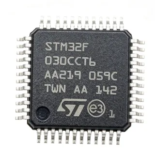
HT66FB550 - 8-bit USB Flash MCU, 8KB, LQFP-48 | Holtek
Teilenummer: HT66FB550 ✓ Aktiv| Menge | Stückpreis | Gesamt |
|---|---|---|
| 1 | $1.44 | $1,44 |
| 10 | $1.32 | $13,20 |
| 100 | $1.18 | $118,00 |
| 500 | $1.05 | $525,00 |
| 1.000 | $0.95 | $950,00 |
HT66FB550 Übersicht
An 8-bit microcontroller unit (MCU) is a single-chip computer that integrates a processor core, memory, and peripherals on one die, sitting within the broader hierarchy of semiconductor devices as: microcontroller -> embedded processor -> integrated circuit. The HT66FB550 belongs to Holtek's A/D Flash USB series, which combines Holtek's high-performance RISC core with direct analog signal interfacing and a USB interface, eliminating the need for a separate USB transceiver chip in many designs.
Key features include the USB 2.0 Full Speed device controller (12 Mbps), a 12-bit resolution analog-to-digital converter, 8KB of Flash program memory, an SPI serial interface, and a wide operating voltage range of 2.2V to 5.5V. These specifications make the device well suited to cost-sensitive designs that must digitize analog sensor signals and stream them over USB without a discrete USB bridge.
Technically, the HT66FB550 uses Holtek's 8-bit high-performance RISC architecture, common to the HT66FB540, HT66FB550, and HT66FB560 family members, which differ mainly in memory density and pin count. The integrated USB serial interface engine (SIE) handles protocol framing in hardware, reducing firmware overhead and CPU loading compared with bit-banged USB implementations.
Typical applications include USB HID devices such as game controllers and keyboards, USB sensor data loggers, battery chargers with USB telemetry, test fixtures, and industrial control panels that interface directly to analog transducers through the 12-bit ADC.
When designing with this device, respect the 2.2V to 5.5V supply range and place 0.1uF decoupling capacitors at each VDD pin; the USB full-speed line requires 22-ohm series resistors and careful 90-ohm differential routing on the DP/DM pair.
This page synthesizes distributor pricing, drop-in family alternatives, application guidance, and design notes not found in the manufacturer datasheet, offering engineering value beyond a raw specification listing.
Drop-in-Alternativen für HT66FB550 – gleiches Gehäuse, Pin-kompatibel. Bauteile mit anderem Gehäuse, die eine PCB-Überarbeitung erfordern, sind ausgeschlossen.
Schnellvergleichstool – Wählen Sie Alternativbauteile für den Direktvergleich:
HT66FB560
✅ Drop-In ⚠️ Spezifikationen ungeprüft📋 Referenzalternative (nicht im Katalog)
HT66FB540
✅ Drop-In ⚠️ Spezifikationen ungeprüft📋 Referenzalternative (nicht im Katalog)
HT66FB550 Grenzwerte & elektrische Eigenschaften
| Core | 8-bit RISC |
| Program Memory Size | 8 KB Flash |
| Operating Voltage Range | 2.2 V to 5.5 V |
| ADC Resolution | 12-bit |
| Number of I/O | 37 |
| USB Interface | USB 2.0 Full Speed (12 Mbps) |
| Communication Interfaces | SPI, USB |
| Gehäuse | LQFP-48 (7x7 mm) |
| Montageart | Surface Mount |
| Architecture | High-performance RISC |
| Product Series | HT66FB540 / HT66FB550 / HT66FB560 A/D Flash USB MCU |
| RoHS-Status | Compliant |
| Typical Applications | USB interface to analog signals |
HT66FB550 lqfp-48 (7x7 mm) Pinbelegungsleitfaden
Pinbelegung für HT66FB550 (lqfp-48 (7x7 mm)-Gehäuse). Dieser digitale IC umfasst GPIO, Kommunikationsschnittstellen (UART, SPI, I2C) und Versorgungspins. Alternative Pin-Funktionen und Konfigurationsoptionen entnehmen Sie dem Herstellerdatenblatt. Unverzichtbar für Embedded-System-Design und PCB-Layout.
Keine detaillierten Pinbelegungsdaten verfügbar für HT66FB550.
Siehe die Datenblatt für die vollständige Pin-Konfiguration.
Typische Anwendungen
HT66FB550 ist geeignet für 6 Anwendungs: USB HID Input Devices, USB Sensor Data Loggers, USB Battery Charger Telemetry, Industrial Control Panels, USB Audio-Accessory Controls, Test Fixtures and Programming Jigs.
USB HID Input Devices
The HT66FB550 fits USB HID applications such as game controllers, keyboards, and rotary encoders because its on-chip USB 2.0 Full Speed serial interface engine delivers the required 12 Mbps device connectivity without an external USB bridge chip, while 37 GPIO lines provide direct switch and LED matrix interfacing. In a typical design, the MCU enumerates as an HID class device, polls switches at 1 kHz or faster, and streams reports over the interrupt endpoint - deterministic timing that the hardware USB SIE maintains independent of firmware load. Because the device runs from 2.2V to 5.5V, it can be powered directly from the USB VBUS 5V rail with a single 0.1uF decoupling capacitor per pin. The trade-off versus a dedicated USB HID chip is firmware development effort, offset by Holtek's HID firmware libraries and lower total BOM cost at volume.
Empfohlen
USB Sensor Data Loggers
For data loggers that digitize analog sensors and offload data over USB, the HT66FB550 combines the two required functions on one die: a 12-bit ADC for direct transducer connection (thermistors, strain bridges, potentiometers, light sensors) and the USB 2.0 Full Speed interface for 12 Mbps transfer to a host PC. The wide 2.2V to 5.5V supply range permits operation from two AA cells or a single Li-ion cell, and the 8KB Flash accommodates ring-buffer logging plus a vendor-class USB stack. In practice, the ADC samples at application-defined intervals, results are stored in RAM, and bulk endpoints stream records when docked. Designers should keep the ADC reference stable under USB load transients by adding bulk capacitance (10uF) near VDD and separating analog ground from the USB connector return path.
Empfohlen
USB Battery Charger Telemetry
The HT66FB550 suits charger accessories that report voltage, current, and temperature to a PC or charger host over USB. The 12-bit ADC measures battery voltage and current-sense amplifier outputs directly, while the USB Full Speed interface implements an HID or vendor-class telemetry endpoint. With 37 I/O lines the MCU also drives charge-status LEDs and controls a pass transistor or relay for charge enable. Because the device operates from 2.2V to 5.5V, it tolerates the 5V VBUS supply with margin, and its Flash memory stores calibration constants without external EEPROM. Firmware should sample current synchronously with the switching charger's PWM period to avoid ripple aliasing, and series resistors (22 ohm) on DP/DM plus a filtered VBUS divider protect the measurement front end from connector transients.
Empfohlen
Industrial Control Panels
In industrial panels and machine accessories that need a PC configuration link, the HT66FB550 provides the USB Full Speed programming/configuration interface alongside its 12-bit ADC for reading analog setpoint potentiometers, and SPI for connecting external EEPROM, displays, or isolated sensors. The LQFP-48 7x7 mm footprint conserves panel-board area, and the industrial-relevant wide voltage range simplifies integration with 5V logic rails. A typical topology uses the ADC for front-panel analog inputs, SPI for a local display or memory, and USB for parameter upload from a host utility. Holtek's Flash memory supports field firmware updates through a bootloader, reducing maintenance cost. Designers should observe ESD protection on the USB connector (TVS diodes) and confirm the operating temperature range on the datasheet matches the enclosure environment.
Empfohlen
USB Audio-Accessory Controls
The HT66FB550 is appropriate for the control side of USB audio accessories - volume knobs, button pods, and status displays - where it enumerates as an HID device and forwards encoder/button events to the host at USB Full Speed (12 Mbps). Its 12-bit ADC reads analog slider and potentiometer positions with fine resolution for smooth volume control, and the 37 GPIO lines drive RGB status LEDs or a small segment display. The device's low per-unit cost (about $1.44 as of 2026-10-11 at LCSC) fits consumer accessory BOM budgets. Note that this MCU performs control/HID functions; it is not itself a USB audio streaming codec, so designs requiring actual I2S audio transport pair it with a dedicated USB audio codec IC while the HT66FB550 manages the user interface and power sequencing.
Empfohlen
Test Fixtures and Programming Jigs
Bench and production test fixtures benefit from the HT66FB550's combination of USB host-side connectivity, 12-bit ADC measurement, SPI expansion, and 37 GPIO for relay and mux control. A fixture MCU enumerates to the operator's PC over USB Full Speed, receives test commands, actuates relays through GPIO, reads DUT analog outputs via the ADC, and returns pass/fail data - all without a separate USB-UART bridge. The 2.2V to 5.5V range matches typical fixture 5V supplies, and the 8KB Flash holds scripted test sequences that can be field-updated via USB bootloader. For measurement integrity, buffer DUT signals before the ADC input, keep the SPI clock lines short, and add TVS protection on the USB port since fixtures see frequent connect/disconnect cycles in production environments.
Empfohlen
Zusammenfassung der empfohlenen Produkte
Technische Referenzdaten für HT66FB550 – Vergleich, Designhinweise und Compliance-Informationen.
Auswahlhilfe
Vergleich mit Alternativen
| Parameter | Dieses Produkt | HT66FB560 | HT66FB540 |
|---|---|---|---|
| Package | LQFP-48 (7x7 mm) | LQFP-48 (7x7 mm) - same family package option | LQFP-48 (7x7 mm) - same family package option |
| Brand | Holtek Semiconductor | Holtek Semiconductor | Holtek Semiconductor |
| Core | 8-bit RISC | 8-bit RISC (same core) | 8-bit RISC (same core) |
| USB Interface | USB 2.0 Full Speed (12 Mbps) | USB 2.0 Full Speed (12 Mbps) | USB 2.0 Full Speed (12 Mbps) |
| ADC Resolution | 12-bit | 12-bit | 12-bit |
| Operating Voltage | 2.2 V to 5.5 V | 2.2 V to 5.5 V | 2.2 V to 5.5 V |
Wichtigste Unterscheidungsmerkmale
- Balanced 8KB Flash density for USB HID firmware (vs. HT66FB540)
- Integrated USB 2.0 Full Speed removes external bridge chips (vs. HT66FB560)
- Wide 2.2V-5.5V supply range enables battery-only designs (vs. Typical 5V-only USB MCU alternatives)
Designhinweise
Place a 0.1uF ceramic decoupling capacitor at every VDD/VSS pin pair of the LQFP-48, within 2 mm of the pins, plus one 10uF bulk capacitor near the supply entry. The USB full-speed PHY is sensitive to supply droop during packet transmission; a shared, poorly decoupled rail shows up as enumeration failures or CRC errors at 12 Mbps. Route the DP/DM pair as a 90-ohm differential pair, keep it under 50 mm, and place 22-ohm series resistors near the MCU pins, following the USB 2.0 full-speed layout practice described in Holtek's USB application notes.
Keep the 12-bit ADC's analog inputs away from the USB DP/DM pair and any SPI clock lines on the LQFP-48. Crosstalk from the 12 Mbps USB traffic into a high-impedance ADC input (source impedance above 10 kohm) produces visible code noise. Add an RC low-pass (e.g., 1 kohm / 10 nF, giving roughly 16 kHz cutoff) at each analog input and sample at times that avoid USB packet bursts if the application is latency-tolerant. Reserve a quiet analog ground island connected to the main ground at a single point near the ADC reference.
Do not assume cross-family pin compatibility without checking the datasheet pinout tables: while the HT66FB540/550/560 share the same architecture, I/O counts and package options differ between family members, and swapping die into an existing LQFP-48 footprint must be verified pin by pin (including VDD/VSS and USB pin placement). Also confirm the operating temperature range for your environment on the datasheet, since consumer-grade temperature limits can be exceeded in sealed enclosures with USB traffic running continuously.
Compliance-Informationen
RoHS compliance stated by LCSC and JLCPCB listings (ROHS). REACH, halogen-free, and conflict-minerals declarations not present in retrieved data - obtain certificates from Holtek.