ISO1430BDW - 12Mbps Isolated RS-485/RS-422 | Texas Instruments
Teilenummer: ISO1430BDW ✓ AktivISO1430BDW Übersicht
Drop-in-Alternativen für ISO1430BDW – gleiches Gehäuse, Pin-kompatibel. Bauteile mit anderem Gehäuse, die eine PCB-Überarbeitung erfordern, sind ausgeschlossen.
Varianten dieser Serie
Modelle derselben Serie, die drop-in-kompatibel sind mit ISO1430BDW (gleiche Bauform und Footprint) – abweichend in EMC Protection, Package.
ISO1430DWR
✅ Drop-InPreis auf Anfrage
Datenblatt ansehen →ISO1410DWR
✅ Drop-InPreis auf Anfrage
Datenblatt ansehen →ISO1430BDW Technische Daten
| Product Type | Galvanically isolated RS-485/RS-422 transceiver |
| Signaling Rate | 12 Mbps |
| Operating Mode | Half-duplex |
| Isolation Rating | 5 kVrms |
| Standards Supported | TIA/EIA RS-485 and TIA/EIA RS-422 |
| Channel Count | 1 transceiver |
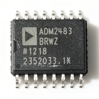
| Gehäuse | 16-pin wide-body SOIC |
| EMC Protection | EMC-protected bus pins |
| Isolation Technology | Silicon-dioxide-based capacitive isolation |
| RoHS-Status | Compliant per manufacturer product-page information |
| Automotive Qualification | Not applicable or not stated in the provided data |
| Montageart | Surface mount |
| Datasheet | Manufacturer ISO1430 datasheet |
ISO1430BDW 16-pin wide-body soic Pinbelegungsleitfaden
Pinbelegung für ISO1430BDW (16-pin wide-body soic-Gehäuse). Pin-Nummerierung, Funktionen und Anschlussdiagramme sind im Herstellerdatenblatt definiert. Entnehmen Sie diesem den genauen Footprint und Lötrichtlinien.

Keine detaillierten Pinbelegungsdaten verfügbar für ISO1430BDW.
Siehe die Datenblatt für die vollständige Pin-Konfiguration.
Typische Anwendungen
ISO1430BDW ist geeignet für 6 Anwendungs: Industrial Sensor Networks, Process Control Equipment, Building and HVAC Networks, Robotics and Factory Automation, Medical and Diagnostic Equipment, Telecommunications and Remote I/O.
Industrial Sensor Networks
The ISO1430BDW fits isolated sensor and controller links where remote equipment communicates over RS-485 or RS-422 in an electrically noisy environment. Its 12-Mbps maximum signaling rate provides more bandwidth than the 500-kbps ISO141x family, while 5-kVrms isolation separates the host electronics from ground shifts and fault energy on the field side. The manufacturer describes the bus pins as tolerant of IEC ESD and IEC EFT disturbances. Place the transceiver between the controller interface and the external bus, use the recommended isolation layout, and apply termination appropriate to the cable topology. Confirm exact supply voltages, logic levels, and ESD levels in the Texas Instruments datasheet before production release.
Empfohlen
Process Control Equipment
For PLC-adjacent instrumentation, the ISO1430BDW provides a galvanically isolated half-duplex path between control electronics and an RS-485 or RS-422 field network. The 12-Mbps capability supports faster data exchange than lower-speed isolated transceivers, and the 5-kVrms isolation rating helps protect control hardware when field-side ground potentials differ. EMC-protected bus pins are valuable in cabinets containing relays, motors, and switching power stages. The design should follow the TI recommended application circuit, preserve separation around the isolation barrier, and include only the termination and protection required by the bus topology. Exact timing, supply, and thermal details remain subject to the manufacturer datasheet.
Empfohlen
Building and HVAC Networks
ISO1430BDW can connect an embedded controller to an isolated building-management or HVAC bus using RS-485 or RS-422. Half-duplex operation suits a shared multidrop network, and the 12-Mbps rating provides substantial throughput for sensor polling and configuration traffic. Its isolation barrier helps separate mains-adjacent equipment from the communications electronics, while the integrated EMC protection targets industrial transient conditions. Designers should use twisted-pair cabling, observe the manufacturer termination and biasing recommendations, and keep the isolation barrier free of copper pours and high-current paths. The data rate, cable length, and transceiver loading must be checked together because the verified record does not specify all timing and termination details.
Empfohlen
Robotics and Factory Automation
The ISO1430BDW is suitable for isolated communications between a robot controller and peripheral equipment exposed to motor noise, contactor switching, and long industrial cables. Its 12-Mbps capability reduces transfer time compared with the 500-kbps ISO141x group, which can help when a node exchanges frequent position or diagnostic data. The half-duplex RS-485/RS-422 interface and 5-kVrms isolation support robust field-bus connections. Maintain short differential routing, use a continuous reference plane, avoid stubs, and place termination only where required by the topology. Validate the complete signal-integrity path with the actual connector, cable, and baud-rate combination.
Empfohlen
Medical and Diagnostic Equipment
ISO1430BDW can provide an isolated communications path in medical or diagnostic equipment that uses an RS-485 or RS-422 link between a host and an external subsystem. The 5-kVrms galvanic isolation helps reduce electrical coupling between host-side electronics and field-side wiring, while the 12-Mbps rate supports efficient data transfer. The manufacturer emphasizes harsh industrial EMC environments rather than specifically certifying this part for medical systems, so engineers must independently validate applicable medical, safety, and system-level isolation requirements. Use the datasheet's recommended barrier layout and confirm that the selected system architecture meets the required separation and leakage criteria.
Empfohlen
Telecommunications and Remote I/O
The ISO1430BDW is appropriate for isolated remote I/O or telecommunications equipment that bridges a central controller to a field bus over RS-485 or RS-422. The 12-Mbps signaling rate supports higher-volume command and diagnostic traffic than the 500-kbps ISO141x family, and the half-duplex architecture supports cost-effective multidrop bus wiring. EMC protection on the bus pins is valuable in racks with switching supplies and long external cables. Place protection and termination components close to the connector, maintain differential pair symmetry, and preserve the isolation creepage and clearance specified by TI. Exact receive thresholds, propagation delay, and supply requirements must be confirmed from the manufacturer datasheet.
Empfohlen
Zusammenfassung der empfohlenen Produkte
Technische Referenzdaten für ISO1430BDW – Vergleich, Designhinweise und Compliance-Informationen.
Auswahlhilfe
Vergleich mit Alternativen
| Parameter | Dieses Produkt | ISO1430DWR | ISO1410DWR |
|---|---|---|---|
| Package | 16-pin wide-body SOIC | 16-pin wide-body SOIC | 16-pin wide-body SOIC |
| Brand | Texas Instruments | Texas Instruments | Texas Instruments |
| Maximum Signaling Rate | 12 Mbps | 12 Mbps | 500 kbps |
| Supported Standards | TIA/EIA RS-485 and RS-422 | TIA/EIA RS-485 and RS-422 | TIA/EIA RS-485 and RS-422 |
| Operating Mode | Half-duplex | Half-duplex | Half-duplex |
| Isolation Technology | Silicon-dioxide-based capacitive isolation | Silicon-dioxide-based capacitive isolation | Silicon-dioxide-based capacitive isolation |
| Channel Count | 1 transceiver | 1 transceiver | 1 transceiver |
| Quoted Unit Price as of 2026-10-30 | Quote required | Quote required | Quote required |
Wichtigste Unterscheidungsmerkmale
- Higher signaling rate within the ISO14xx family (vs. ISO1410DWR)
- EMC-focused isolated bus interface (vs. ISO1410DWR)
- Isolation and communication in one package (vs. SN75174DWR)
Designhinweise
Maintain the isolation barrier copper keepout and creepage/clearance specified by Texas Instruments. Keep bus-side and logic-side return currents separate, avoid placing high-current paths beneath the isolation barrier, and do not connect the two ground domains except where the system architecture intentionally permits a defined connection. The device uses silicon-dioxide-based capacitive isolation, so the physical barrier layout is part of the isolation performance rather than only a mechanical constraint.
Route the RS-485 or RS-422 differential pair as a tightly coupled pair over a continuous reference plane, keep the pair length matched where practical, and avoid stubs and uncontrolled branch connections. At 12 Mbps, connector transitions, cable impedance, clock skew, and transceiver timing can materially affect eye closure. Validate the complete path with the actual cable and termination arrangement rather than relying only on nominal baud-rate calculations.
Do not treat ISO1410DWR as an unconditional substitute for ISO1430BDW merely because both use a 16-pin wide-body SOIC. The verified ISO14xx family information places ISO141x at up to 500 kbps and ISO143x at up to 12 Mbps. A 500-kbps device changes communication timing and may not satisfy the original system's throughput requirement. Confirm pin functions, supply levels, enable behavior, timing, and isolation parameters in the exact replacement datasheet.
Place transient-protection and bus-termination components close to the external connector, and use the manufacturer recommended application circuit for EMC protection. The bus pins are intended to withstand ESD and EFT events, but external connectors and cables can introduce events beyond the device's internal protections. Maintain short return paths and define a deliberate grounding and surge strategy for the installation to prevent external transients from bypassing the transceiver's protection network.
Compliance-Informationen
RoHS compliance is identified in the supplied manufacturer and comparison information. The provided verified data does not establish REACH, lead-free, halogen-free, conflict-minerals, or automotive qualification status. ISO1430 is an industrial interface device; AEC-Q100 is not indicated.