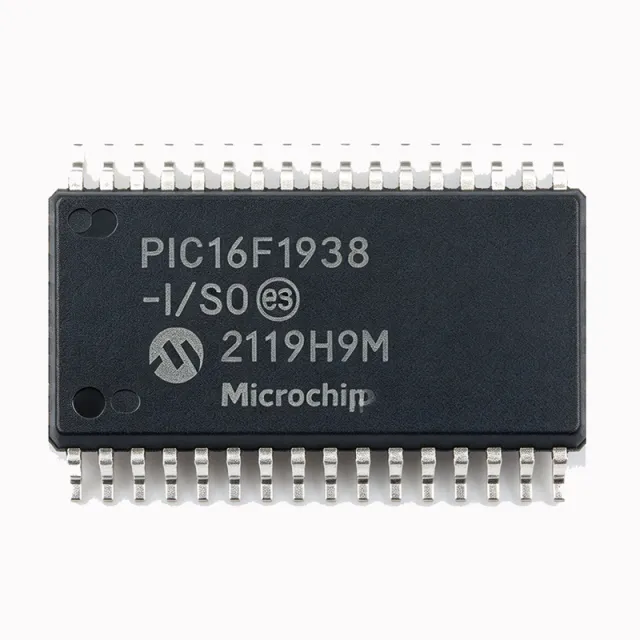
PIC16F1938-I/SO - 28KB Flash 8-bit MCU LCD Driver | Microchip
Teilenummer: PIC16F1938-I/SO ✓ Aktiv| Menge | Stückpreis | Gesamt |
|---|---|---|
| 1 | $3.42 | $3,42 |
| 10 | $3.07 | $30,70 |
| 100 | $2.73 | $273,00 |
| 500 | $2.45 | $1.225,00 |
| 1.000 | $2.18 | $2.180,00 |
PIC16F1938-I/SO Übersicht
An 8-bit microcontroller (MCU) is a small, self-contained computer-on-a-chip that combines a CPU, non-volatile program memory (flash), volatile data memory (RAM), and a rich set of peripherals on a single silicon die. Within the broader semiconductor taxonomy, an MCU belongs to the microcontrollers family, which itself is a sub-category of microprocessors and digital logic ICs. The PIC16F1938 sits in the PIC16 mid-range family from Microchip, optimized for low-power general-purpose embedded control with on-chip LCD drive capability and segment display driving.
Key features include a 10-bit ADC with up to 17 channels, a 5-bit DAC, enhanced PWM with multiple complementary outputs, multiple communication interfaces (UART, SPI, I2C), and an integrated LCD driver supporting up to 96 segments. The 32MHz internal oscillator and four 8-bit timers plus one 16-bit timer deliver deterministic real-time control, while the 14-bit instruction width enables compact code density.
The PIC16F1938 uses a Harvard RISC architecture with a 15-bit, 16-word hardware call stack and 49 instruction opcode set. The internal voltage reference, mTouch capacitive sensing module, and zero-cross detect simplify mixed-signal designs. The device is fabricated on a low-power CMOS process, achieving industry-leading sleep current that allows battery-powered and energy-harvesting designs to operate for years on a single cell.
Typical applications include consumer appliances, battery-powered instruments with LCD readouts, industrial control panels, white goods and metering equipment, automotive body electronics, and IoT edge sensor nodes. Designers choose this part when segment-LCD UI, ultra-low standby current, and a small 28-pin SOIC footprint matter most.
When designing with this MCU, allocate a 0.1uF decoupling capacitor within 5 mm of VDD, and connect the ICSPCLK/ICSPDAT pins to a header for in-circuit serial programming. The brown-out reset (BOR) and watchdog timer should remain enabled in safety-critical applications.
This page synthesizes current distributor pricing, drop-in alternatives from the same PIC16F193x family and competing 8-bit MCUs, and practical design notes not found in the manufacturer datasheet.
Drop-in-Alternativen für PIC16F1938-I/SO – gleiches Gehäuse, Pin-kompatibel. Bauteile mit anderem Gehäuse, die eine PCB-Überarbeitung erfordern, sind ausgeschlossen.
Varianten dieser Serie
Modelle derselben Serie, die drop-in-kompatibel sind mit PIC16F1938-I/SO (gleiche Bauform und Footprint) – abweichend in Package, ADC, Timers, LCD Driver, Operating Temperature.
Schnellvergleichstool – Wählen Sie Alternativbauteile für den Direktvergleich:
PIC16LF1938-I/SO
✅ Drop-In✓ Auf Lager
$1.74 / Stück
Datenblatt ansehen →PIC16F1938-I/SP
✅ Drop-In📋 Referenzalternative (nicht im Katalog)
PIC16F1938-E/SO
✅ Drop-In✓ Auf Lager
$1.97 / Stück
Datenblatt ansehen →PIC16F1936-I/SO
✅ Drop-In✓ Auf Lager
$1.74 / Stück
Datenblatt ansehen →PIC18F2520-I/SO
✅ Drop-In✓ Auf Lager
$4.65 / Stück
Datenblatt ansehen →PIC16F19186-I/PT
✅ Drop-In✓ Auf Lager
$1.82 / Stück
Datenblatt ansehen →PIC16F1938-I/SO Grenzwerte & elektrische Eigenschaften
| Architecture | 8-bit PIC RISC (Harvard) |
| Program Memory (Flash) | 28 KB |
| RAM | 1 KB |
| EEPROM | 256 bytes |
| Instruction Width | 14-bit |
| Instruction Set | 49 instructions |
| Hardware Stack | 16-level x 15-bit |
| Maximum CPU Speed | 32 MHz |
| Operating Voltage | 1.8 V to 5.5 V |
| ADC | 10-bit, up to 17 channels |
| DAC | 5-bit |
| Timers | 4 x 8-bit + 1 x 16-bit |
| Communication | UART, SPI, I2C |
| LCD Driver | Up to 96 segments |
| PWM Channels | Enhanced, complementary outputs |
| Special Features | mTouch capacitive sensing, zero-cross detect |
| Sleep Current (typical) | 50 nA |
| Betriebstemperatur | -40 C to +85 C (Industrial) |
| Gehäuse | 28-pin SOIC (SO) wide-body |
| Terminal Pitch | 1.27 mm |
| Montageart | Surface Mount |
| RoHS-Status | Compliant |
PIC16F1938-I/SO Pin-Konfiguration
| Pin 1 | RA0/AN0/C1IN+/C2IN+/VCAP — Analog input 0 / LCD voltage cap |
| Pin 2 | RA1/AN1/C1IN-/C2IN-/SEG12 — Analog input 1 / LCD segment 12 |
| Pin 3 | RA2/AN2/VREF-/C2IN+/SEG13 — Analog input 2 / VREF- / LCD segment 13 |
| Pin 4 | RA3/AN3/VREF+/C1IN+/SEG14 — Analog input 3 / VREF+ / LCD segment 14 |
| Pin 5 | RA4/AN4/C1OUT/SRQ/SEG15 — Analog input 4 / LCD segment 15 |
| Pin 6 | RA5/AN5/C2OUT/SEG16 — Analog input 5 / LCD segment 16 |
| Pin 7 | RA6/OSC2/CLKOUT/SEG17 — Oscillator output / LCD segment 17 |
| Pin 8 | RA7/OSC1/CLKIN/SEG18 — Oscillator input / LCD segment 18 |
| Pin 9 | VSS — Ground reference |
| Pin 10 | RB0/AN12/CCP4/SDA/SEG0/BIAS1 — I/O with interrupt / I2C data / LCD bias |
| Pin 11 | RB1/AN10/CPS0/CCP5/RX/DT/SEG1 — UART RX / I2C clock / mTouch input |
| Pin 12 | RB2/AN8/CPS1/P1B/TX/CK/SEG2 — UART TX / PWM / mTouch |
| Pin 13 | RB3/AN9/CPS2/CCP3/SEG3 — PWM / mTouch / LCD segment |
| Pin 14 | RB4/AN11/CPS3/SCL/SEG4 — I2C clock / LCD segment |
| Pin 15 | RB5/AN13/CPS4/SEG5 — LCD segment 5 |
| Pin 16 | RB6/ICSPCLK/CCP1/SEG6 — ICSP clock / PWM / LCD segment |
| Pin 17 | RB7/ICSPDAT/CCP2/SEG7 — ICSP data / PWM / LCD segment |
| Pin 18 | VSS (second) — Ground reference |
| Pin 19 | VDD — Positive supply voltage |
| Pin 20 | RA0/VCAP — Voltage regulator bypass |
| Pin 21 | RC0/T1OSO/T1CKI/SOSCO/SEG19 — Timer1 oscillator / LCD segment 19 |
| Pin 22 | RC1/T1OSI/SOSCI/SEG20 — Timer1 oscillator / LCD segment 20 |
| Pin 23 | RC2/AN14/CPS5/P1D/SEG21 — Analog input 14 / PWM / LCD segment |
| Pin 24 | RC3/AN15/CPS6/SEG22 — Analog input 15 / LCD segment 22 |
| Pin 25 | RC4/AN16/CPS7/SEG23 — Analog input 16 / LCD segment 23 |
| Pin 26 | RC5/CCP2/SEG24 — PWM / LCD segment 24 |
| Pin 27 | RC6/AN12/TX/CK/CCP3/SEG25 — UART TX / PWM / LCD segment |
| Pin 28 | RC7/AN13/RX/DT/CCP4/SEG26 — UART RX / PWM / LCD segment |
Typische Anwendungen
PIC16F1938-I/SO ist geeignet für 7 Anwendungs: Industrial Control Panel with LCD, Battery-Powered Metering Equipment, Consumer Appliance Control, Automotive Body Electronics, IoT Edge Sensor Node, White Goods User Interface, Portable Medical Monitoring Devices.
Industrial Control Panel with LCD
The PIC16F1938-I/SO is ideal for industrial control panels with LCD readouts. Its integrated segment LCD driver supports up to 96 segments on the 28-pin package, eliminating an external LCD controller and reducing BOM cost. The 50 nA sleep current enables panel-mounted devices to remain in standby for years on a single coin cell when AC power is removed. The 10-bit ADC provides sensor input digitisation, while the mTouch capacitive sensing module adds touch button interfaces without additional components. The -40 C to +85 C industrial temperature range covers factory floor environments. According to the datasheet typical application circuit, the panel connects via I2C to remote HMI modules. This architecture fits pump controllers, HVAC thermostats, and machine operator panels.
Empfohlen
Battery-Powered Metering Equipment
Water, gas, and electricity meters benefit from the PIC16F1938-I/SO's 50 nA sleep current, 1.8V to 5.5V operating range, and integrated LCD driver. A typical smart meter wakes every second to count pulses, accumulates data in 1KB RAM, and returns to sleep. With WDT enabled, sleep current remains at approximately 500 nA typical, providing multi-year battery life. The integrated charge pump allows direct LCD drive even from a single 1.5V cell after boost conversion. The 10-bit ADC monitors battery voltage and sensor inputs, while the UART/SPI/I2C interfaces support module communication. According to the datasheet, the segment LCD controller handles up to 8 common plus 12 segment pins in the 28-pin SOIC, suitable for multi-digit totalizer displays.
Empfohlen
Consumer Appliance Control
The PIC16F1938-I/SO drives consumer appliances such as coffee machines, washing machines, and microwave ovens. The 28KB flash accommodates complex user interface state machines, while the 256 bytes EEPROM stores user preferences and calibration data across power cycles. The enhanced PWM module provides complementary outputs suitable for direct motor drive via half-bridge circuits or for power-factor-controlled heating elements. The mTouch capacitive sensing replaces mechanical buttons with capacitive sliders and wheels, improving reliability and enabling sealed front panels. The integrated segment LCD shows time, temperature, and program status. Operating from 1.8V to 5.5V, it interfaces directly with rectified mains-derived 3.3V or 5V rails, simplifying the power supply.
Empfohlen
Automotive Body Electronics
The PIC16F1938-I/SO supports automotive body electronics applications including HVAC control heads, instrument clusters, and body control modules. Its industrial -40 C to +85 C temperature grade covers most under-dash installations. The integrated LIN-compatible UART enables connection to vehicle body networks, while the PWM outputs drive LED backlighting and motor actuators. The 10-bit ADC reads sensor inputs including temperature, humidity, and switch positions. Designers can leverage the LCD driver for non-safety display modules. For under-hood or harsher environments, the PIC16F1938-E/SO extended temperature variant should be selected. The automotive-grade part number for AEC-Q100 qualification is available as PIC16F1938T-I/SO from Microchip's automotive portfolio.
Empfohlen
IoT Edge Sensor Node
IoT edge sensor nodes benefit from the PIC16F1938-I/SO's nanoWatt XLP sleep mode and integrated peripherals. A typical sensor node spends 99% of its time in sleep at 50 nA, waking on a timer interrupt to read sensors via I2C, transmit over SPI/UART radio, and return to sleep. With an average duty cycle of 0.1%, battery life exceeds 10 years on a CR2032 coin cell. The 28KB flash accommodates LoRaWAN or BLE stack libraries plus application code. The 10-bit ADC enables direct analog sensor interface. The mTouch capacitive sensing allows touch-based user input without buttons. The 256-byte EEPROM stores node ID and calibration constants. This combination of ultra-low sleep current, ample flash, and rich peripherals in a small 28-SOIC package enables compact wireless sensor designs.
Empfohlen
White Goods User Interface
White goods such as refrigerators, dishwashers, and ovens integrate the PIC16F1938-I/SO for touch-based user interfaces with LCD displays. The mTouch capacitive sensing eliminates mechanical buttons, improving reliability and enabling sealed facias. The segment LCD driver shows temperatures, program selections, and countdown timers without external driver chips. The 28KB flash holds UI state machines and self-test routines, while 1KB RAM supports menu navigation stacks. The 256-byte EEPROM retains user settings across power cycles. The enhanced PWM drives indicator LEDs and small buzzers. Industrial temperature grade ensures reliable operation in kitchen environments with high humidity. The 1.8V to 5.5V range supports direct connection to rectified 3.3V rails, simplifying the power tree.
Empfohlen
Portable Medical Monitoring Devices
Portable medical monitoring devices such as glucose meters, pulse oximeters, and thermometers leverage the PIC16F1938-I/SO's low power consumption and integrated LCD. The 50 nA sleep current extends battery life to multi-year spans in non-connected storage. The 10-bit ADC digitises sensor signals with adequate resolution for vital sign display. The segment LCD driver provides direct readout without an external display controller, reducing PCB area. The 32MHz instruction rate executes signal processing algorithms within real-time constraints. Brown-out reset (BOR) and watchdog timer maintain safe operation. The mTouch capacitive sensing allows sealed enclosures meeting medical IP54 ratings. Note: This part is industrial grade; for FDA-grade medical applications requiring full IEC 60601 compliance, additional qualification and design controls are required.
Empfohlen
Zusammenfassung der empfohlenen Produkte
Technische Referenzdaten für PIC16F1938-I/SO – Vergleich, Designhinweise und Compliance-Informationen.
Auswahlhilfe
Vergleich mit Alternativen
| Parameter | Dieses Produkt | PIC16LF1938-I/SO | PIC16F1938-I/SP | PIC16F1938-E/SO | PIC16F1936-I/SO | PIC18F2520-I/SO |
|---|---|---|---|---|---|---|
| Brand | Microchip Technology | Microchip Technology | Microchip Technology | Microchip Technology | Microchip Technology | Microchip Technology |
| Package | 28-pin SOIC (SO) wide-body | 28-pin SOIC (SO) - same | 28-pin SPDIP (SP) - through-hole | 28-pin SOIC (SO) - same | 28-pin SOIC (SO) - same | 28-pin SOIC (SO) - same |
| Program Memory (Flash) | 28 KB | 28 KB | 28 KB | 28 KB | 14 KB (-50%) | 32 KB |
| RAM | 1 KB | 1 KB | 1 KB | 1 KB | 1 KB | 1.5 KB |
| EEPROM | 256 bytes | 256 bytes | 256 bytes | 256 bytes | 256 bytes | 256 bytes |
| Operating Voltage | 1.8 V to 5.5 V | 1.8 V to 3.6 V (LF) | 1.8 V to 5.5 V | 1.8 V to 5.5 V | 1.8 V to 5.5 V | 2.0 V to 5.5 V |
| Operating Temperature | -40 C to +85 C (Industrial) | -40 C to +85 C | -40 C to +85 C | -40 C to +125 C (Extended) | -40 C to +85 C | -40 C to +85 C |
| LCD Driver Segments | Up to 96 | Up to 96 | Up to 96 | Up to 96 | Up to 96 | None (no LCD) |
| Architecture / Instruction Set | PIC16 RISC (14-bit, 49 inst.) | PIC16 RISC (same) | PIC16 RISC (same) | PIC16 RISC (same) | PIC16 RISC (same) | PIC18 RISC (16-bit, requires code recompilation) |
| RoHS Status | Compliant | Compliant | Compliant | Compliant | Compliant | Compliant |
Wichtigste Unterscheidungsmerkmale
- Industrial temperature range with extended variant available (vs. PIC16F1938-E/SO)
- Pin-compatible PIC16F1936 alternative with smaller flash (vs. PIC16F1936-I/SO)
- LCD driver integrated - no external LCD controller needed (vs. PIC18F2520-I/SO)
Designhinweise
Place a 0.1uF ceramic decoupling capacitor within 5 mm of the VDD pin, with a short trace to the VSS pin. Add a bulk capacitor (4.7uF to 10uF) on the VDD rail if the system has high-current peripherals. The internal voltage regulator requires a 0.1uF bypass capacitor on the VCAP pin (RA0/VCAP function) for stable operation across all load conditions. Estimated: at 32MHz and 5V supply with all peripherals active, current consumption is approximately 5 mA typical; sleep mode drops to 50 nA typical with WDT disabled.
Route the ICSPCLK (RB6) and ICSPDAT (RB7) signals directly to a programming header or test pads. These pins must not be pulled to logic low at power-up; if used for general I/O, add a resistive isolator or buffer for the programmer connection. Keep the 28-pin SOIC wide-body footprint on a 1.27 mm pitch to maintain compatibility with all Microchip PIC16F1938 package variants. According to Microchip layout guidelines, the exposed thermal pad (if present) must be soldered to a continuous ground plane for optimal thermal dissipation.
Do not exceed the absolute maximum VDD of 6.5V (datasheet Section 30.0) or ESD-sensitive pins may be damaged. Always enable the brown-out reset (BOR) for safety-critical designs - this prevents code execution from corrupted flash when VDD droops below the BOR threshold. When migrating from PIC16F1936 (14 KB flash) to PIC16F1938 (28 KB flash), verify linker configuration matches the larger memory map; otherwise compilation may fail. The mTouch capacitive sensing pins require careful PCB layout - trace lengths should not exceed 50 mm and ground plane spacing must follow Microchip AN1478 guidelines.
The integrated LCD driver outputs require careful trace routing to avoid cross-coupling with sensitive analog signals. According to Microchip AN658, place LCD segment and common traces on a separate signal layer or at the PCB edge with at least 0.5 mm spacing from adjacent analog traces. The charge pump switching frequency can couple into the ADC; enable the ADC during display blanking intervals for highest accuracy readings. For optimal ADC performance, ground plane should be solid under the analog input pins (AN0-AN16) with no signal traces passing beneath the ADC-related pins.
Compliance-Informationen
RoHS compliant per Microchip product page. Industrial temperature grade -40C to +85C, not AEC-Q100 qualified. For AEC-Q100 automotive grade, contact Microchip for the -I/SO automotive part variant. Lead-free and halogen-free packaging per Microchip environmental compliance data.






