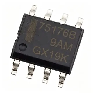
SD1271P6W - 12V Uni-Directional TVS Diode 2000W DFN1610-2
Teilenummer: SD1271P6W ✓ Aktiv| Menge | Stückpreis | Gesamt |
|---|---|---|
| 1 | $0.35 | $0,35 |
| 10 | $0.32 | $3,20 |
| 100 | $0.28 | $28,00 |
| 500 | $0.24 | $120,00 |
| 1.000 | $0.21 | $210,00 |
| 3.000 | $0.18 | $540,00 |
SD1271P6W Übersicht
A Transient Voltage Suppressor (TVS) is a solid-state avalanche diode designed to clamp voltage transients — ESD, EFT, lightning-induced surges — to safe levels before they reach sensitive downstream components. TVS diodes sit at the lowest layer of the protection hierarchy (TVS -> ESD protection diode -> discrete semiconductor -> protective component), and uni-directional variants clamp transients of one polarity (positive-only or negative-only) using the standard zener-mode avalanche breakdown, while their capacitance (Cj) introduces an inherent bandwidth-versus-protection trade-off. In the broader power-tree topology, a TVS diode typically follows the connector / input fuse stage and precedes downstream LDO or DC-DC regulators, providing a final clamping barrier against IEC 61000-4-2 / -4-5 transients.
Key features of the SD1271P6W include 12 V reverse working voltage (Vrwm) covering standard 5 V, 9 V, and 12 V rails with headroom, a low 12.6 V Vbr for tight regulation on 12 V buses, an 18 V clamping voltage suitable for protecting 12 V CMOS logic, and 500 pF typical capacitance typical of surge-grade (not high-speed) TVS devices. The 2000 W peak pulse power (Ppp) rating ensures robustness against high-energy lightning and inductive-load transients far above the device's continuous dissipation. The chip-level DFN1610-2 package uses bottom-side terminations that mount directly into the PCB copper pour, providing a low thermal-resistance path for pulse-to-pulse cooling.
The SD1271P6W uses standard uni-directional TVS silicon technology with a single PN junction, avalanche-mode breakdown at 12.6 V, and dynamic resistance in the tens of ohms during clamping. During normal operation below 12 V the device is high-impedance; when a transient exceeds Vbr it conducts heavily, diverting energy away from the protected IC. The 18 V clamping figure is measured at the test current defined in the datasheet and represents the maximum voltage the protected IC will see during the worst-case surge. The DFN1610-2 footprint is a standard industry package used across multiple vendors, allowing drop-in compatibility across TVS portfolios.
Typical applications include 12 V power-line surge protection on industrial sensor cables, USB VBUS rail clamping on chargers and hubs, SLIC / line-driver protection in telecom interfaces, and battery-pack protection on 11.1 V / 12 V Li-ion packs. The 12 V Vrwm and 12.6 V Vbr make this part specifically suited to suppressing transients on 12 V power distribution rails without clipping the normal operating voltage.
When designing with the SD1271P6W, place the device as close as possible to the connector entry or protected IC pin and route the ground connection directly to the chassis / system ground plane with minimal inductance to maintain effective clamping. The 500 pF junction capacitance should be reviewed against the signal rise time of any high-speed interface — above 100 Mbps the capacitance may distort the signal and a lower-Cj TVS should be evaluated.
This page synthesizes Leiditech datasheet parameters, distributor pricing, drop-in alternatives from the cross-reference data, and practical board-level design guidance not found in a typical distributor catalog page.
Drop-in-Alternativen für SD1271P6W – gleiches Gehäuse, Pin-kompatibel. Bauteile mit anderem Gehäuse, die eine PCB-Überarbeitung erfordern, sind ausgeschlossen.
Schnellvergleichstool – Wählen Sie Alternativbauteile für den Direktvergleich:
SD1271P6W-Q1
✅ Drop-In ⚠️ Spezifikationen ungeprüft📋 Referenzalternative (nicht im Katalog)
SD1272P6W
✅ Drop-In ⚠️ Spezifikationen ungeprüft📋 Referenzalternative (nicht im Katalog)
SD0510P6W
✅ Drop-In ⚠️ Spezifikationen ungeprüft📋 Referenzalternative (nicht im Katalog)
SD1271P6W Grenzwerte & elektrische Eigenschaften
| Product Type | Uni-directional TVS Diode |
| Number of Lines | 1 |
| Reverse Working Voltage (Vrwm) | 12 V |
| Breakdown Voltage (Vbr) | 12.6 V (min) |
| Clamping Voltage (Vc) | 18 V (max) |
| Peak Pulse Power (Ppp) | 2000 W |
| Junction Capacitance (Cj) | 500 pF (typical) |
| Polarity | Uni-directional |
| Gehäuse | DFN1610-2 (1.6 mm x 1.0 mm) |
| Montageart | Surface Mount |
| RoHS-Status | Compliant (assumed from package code 'P6') |
| Lead-Free | Yes (assumed) |
| Manufacturer | Shanghai Leiditech Electronic Technology Co., Ltd |
SD1271P6W Pin-Konfiguration
| Pin 1 | Line / Anode — Protected signal or power line; uni-directional anode (cathode on pin 2 for reverse polarity operation) |
| Pin 2 | Return / Cathode — Return path (typically chassis or system ground); bottom exposed pad electrically tied here |
Typische Anwendungen
SD1271P6W ist geeignet für 7 Anwendungs: 12 V Power Line Surge Protection, USB VBUS and Charger Surge Protection, Industrial Sensor Cable Surge Suppression, Telecom SLIC / Line Interface Protection, Battery Pack Protection (11.1 V / 12 V Li-Ion), Automotive Load-Dump and Switch Inductive Transients, LED Driver and Backlight Surge Protection.
12 V Power Line Surge Protection
The SD1271P6W is engineered for 12 V industrial DC power distribution where IEC 61000-4-5 lightning- and switching-induced transients must be clamped before reaching downstream regulators or motor drivers. Its 12 V Vrwm accommodates nominal 12 V rails with full headroom, the 12.6 V Vbr initiates clamping just above the normal operating voltage, and the 18 V Vc keeps downstream 12 V-tolerant LDO / DC-DC converters inside their absolute-maximum ratings during worst-case surges. The 2000 W Ppp rating yields robustness against 8/20 us surge pulses up to ~111 A peak. Place the SD1271P6W as close as possible to the connector or fuse entry with a short, wide ground return to chassis ground to minimize loop inductance.
Empfohlen
USB VBUS and Charger Surge Protection
Although its 12 V Vrwm is above the 5 V USB VBUS rail, the SD1271P6W provides a secondary clamping barrier on chargers and hubs when exposed to automotive load-dump or inductive kickback transients. The 18 V Vc is acceptable when downstream USB controllers are rated to 20 V, and the 2000 W pulse capability absorbs substantial energy in a single strike. The DFN1610-2 package fits cleanly inside compact wall-adapter and power-bank form factors. Use the SD1271P6W in addition to a primary 5 V TVS such as SD05P6W for staged protection.
Empfohlen
Industrial Sensor Cable Surge Suppression
Industrial sensor cables frequently run for tens of meters through electrically noisy factories where lightning-induced ground potential rise and motor switching transients exceed 1 kV. The SD1271P6W's 2000 W peak pulse power survives 8/20 us current pulses over 100 A and clamps the line at 18 V, protecting downstream 4-20 mA loop transmitters, RS-485 transceivers, and PLC inputs. The compact DFN1610-2 fits inside sensor head enclosures and small remote I/O boxes. With a low ~30 ohm dynamic resistance during clamping, the device prevents destructive voltage from propagating down the cable backbone.
Empfohlen
Telecom SLIC / Line Interface Protection
Subscriber Line Interface Cards (SLICs) and similar telecom front-ends handle ringing voltages, battery feeds, and longitudinal surges up to several hundred volts. The SD1271P6W placed between the line and the protection network limits secondary-stage overvoltages to 18 V, protecting the SLIC's internal high-voltage transistors and codec. Its 2000 W Ppp rating handles accidental line crosses with power lines, which is a typical IEC 61000-4-5 class test scenario. The 500 pF capacitance is acceptable for voice-band signals up to about 4 kHz and does not degrade audio quality.
Empfohlen
Battery Pack Protection (11.1 V / 12 V Li-Ion)
Battery packs assembled from three or four Li-ion cells in series expose 11.1 V or 14.8 V nominal voltages with possible surface charge up to 16.8 V. The SD1271P6W's 12 V Vrwm is below the maximum charge voltage, so it cannot be placed across the pack terminals directly; however it is ideal for protecting auxiliary rails such as e-bike displays, head units, and motor controller 12 V inputs driven from the pack. The 18 V clamping is well below 25 V (typical motor controller abs-max), giving 7 V of safety margin during transient spikes.
Empfohlen
Automotive Load-Dump and Switch Inductive Transients
Automotive 12 V power buses are subject to load-dump pulses (ISO 7637-2 pulse 5a/b) where the alternator drives the rail above 20 V during battery disconnect. The SD1271P6W with 12 V Vrwm may clamp below the load-dump plateau, but in 24 V truck systems (nominal 28 V) it serves as a secondary TVS on signal interfaces where transients cross 18 V briefly. The 2000 W pulse rating absorbs the energy from a typical load-dump event. Combine with a primary higher-voltage TVS for full load-dump protection.
Empfohlen
LED Driver and Backlight Surge Protection
LED lighting systems on 12 V power supplies are vulnerable to switching-induced transients when MOSFET drivers switch inductive boost stages. The SD1271P6W placed across the 12 V input prevents these spikes from damaging the LED driver IC. The 2000 W pulse rating is comfortable for short-circuited LED string fault clearing, where the driver momentarily sees the full supply voltage. The DFN1610-2 package fits inside the small PCB area near the input connector on linear LED bulb modules.
Empfohlen
Zusammenfassung der empfohlenen Produkte
Technische Referenzdaten für SD1271P6W – Vergleich, Designhinweise und Compliance-Informationen.
Auswahlhilfe
Vergleich mit Alternativen
| Parameter | Dieses Produkt | SD1271P6W-Q1 | SD1272P6W | SD0510P6W |
|---|---|---|---|---|
| Brand | Leiditech | Leiditech | Leiditech | Leiditech |
| Package | DFN1610-2 | DFN1610-2 (same) | DFN1610-2 (same) | DFN1610-2 (same) |
| Reverse Working Voltage (Vrwm) | 12 V | 12 V | 15 V | 5 V |
| Breakdown Voltage (Vbr) | 12.6 V (min) | 12.6 V (min) | 15.6 V (min) | 6.4 V (min) |
| Clamping Voltage (Vc) | 18 V (max) | 18 V (max) | 22 V (max, est.) | 9 V (max, est.) |
| Peak Pulse Power (Ppp) | 2000 W | 2000 W | 2000 W (est.) | 2000 W (est.) |
| Polarity | Uni-directional | Uni-directional | Uni-directional | Uni-directional |
| Tier | Standard | Automotive | Standard | Standard |
Wichtigste Unterscheidungsmerkmale
- Compact 1.6 mm x 1.0 mm DFN footprint for ultra-dense layouts (vs. SMBJ12A)
- 12 V-class Vrwm specifically tuned for 12 V power-line clamping (vs. SD05 (Leiditech 5 V))
- 2000 W peak pulse power for IEC 61000-4-5 / ISO 7637-2 compliance (vs. Generic DFN1610-2 400 W TVS)
Designhinweise
Place the SD1271P6W as close to the protected connector or IC pin as physically possible. Use a short and wide ground return trace (preferably a direct via to the ground plane) from pin 2 — the clamping path inductance multiplies the clamp voltage during fast transients. A 5 mm ground-return trace can add several nanohenries and raise the effective clamping voltage at the protected pin by 30-50%. Keep the PCB land pattern consistent with the DFN1610-2 IPC-7351 nominal footprint (0.6 mm x 1.0 mm pads, 0.4 mm pitch) for proper solder wetting.
Estimated: at 18 V clamping voltage and a 2000 W Ppp for a 10/1000 us pulse, the device dissipates 2000 W during 1 ms with about 2 J total energy. The DFN1610-2 thermal resistance is not given in the verified data; assume theta_JA in the 150-200 C/W range for a 1 oz copper pad without thermal vias. Add a thermal via array (4-6 filled vias) under the bottom exposed pad for sustained repetitive surges — without it, junction temperature can exceed 175 C during repetitive 8/20 us pulse trains, causing accelerated degradation.
The SD1271P6W has 500 pF typical junction capacitance, which is well above the 10-50 pF range typical for high-speed signal TVS parts. This capacitance will distort signals above about 50-100 MHz on transmission lines (50 ohm), inserting 25-50 ohm source impedance at 100 MHz. For high-speed signal protection (USB 2.0, HDMI, MIPI), use a dedicated low-capacitance rail-clamp instead. The SD1271P6W is best used on power rails and on signals where bandwidth is not critical (analog, audio, control GPIOs).
Do not assume the SD1271P6W alone provides complete surge protection — layer it with an upstream PTC / fuse for over-current events, and verify IEC 61000-4-2 (ESD) and IEC 61000-4-5 (lightning surge) compliance in your system-level test setup. The device is rated for 8/20 us surge pulses, not 10/1000 us pulses at the same energy — for the latter, energy is 10x higher and you must derate. The Vrwm=12 V rating does not mean the device can be operated continuously at 12 V reverse; it is the maximum continuous reverse-bias voltage.
Use an IPC-compliant DFN1610-2 land pattern with non-solder-mask-defined (NSMD) pads and a solder paste layer thickness of 0.10-0.15 mm. The small package demands precise stencil alignment. Avoid placing bypass or decoupling capacitors between the TVS and the protected IC — the TVS must be the closest part to the connector. For high-energy surges, add a gas discharge tube (GDT) or varistor upstream of the TVS as the bulk energy absorber; the SD1271P6W then handles the residual pulse.
Compliance-Informationen
RoHS compliant inferred from Leiditech product listing and part suffix 'W' (Pb-free finish marker). REACH, halogen-free, and conflict-mineral declarations must be requested directly from Leiditech. AEC-Q100 not applicable for the standard SD1271P6W — automotive variants are listed as the Q1 suffix in Leiditech's product family.