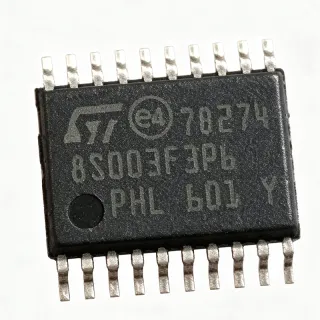
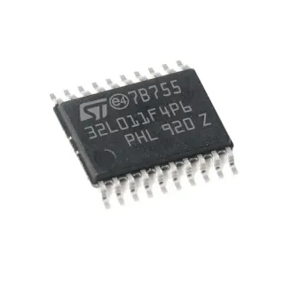
STM8S103F3P3 - 16MHz 8-Bit MCU, 8KB Flash | STMicroelectronics
Teilenummer: STM8S103F3P3 ✓ AktivSTM8S103F3P3 Übersicht
An STM8S microcontroller belongs to the 8-bit embedded-microcontroller hierarchy, where an MCU integrates a CPU core, program memory, data memory, peripherals, and interface logic on one semiconductor die. The STM8S103F3 access line is positioned for compact embedded applications where a modest processing rate, useful analog measurement, and multiple serial interfaces are more important than high-bandwidth computation. Its integrated true data EEPROM also allows frequently changed calibration or configuration data to be stored separately from program Flash.
Three principal characteristics define this device: a maximum 16 MHz operating frequency, up to 8 Kbytes of Flash program memory, and a 10-bit ADC. The STM8S103F3P3 additionally provides three timers and UART, SPI, and I2C serial interfaces. These resources allow a design to measure analog inputs, control timing-dependent outputs, and communicate with sensors, transceivers, displays, or external nonvolatile memories without requiring several separate interface devices.
The STM8S103F3P3 uses STMicroelectronics' STM8 8-bit architecture and is associated with the STM8S103F2/x3 access-line family. At 16 MHz, the device provides substantially more timing headroom than an 8 MHz-class MCU while retaining the straightforward programming model and integrated peripherals expected from an entry-level 8-bit platform. The available verified information does not specify RAM size, ADC resolution details beyond 10-bit capability, or individual peripheral timing ratings, so those details should be confirmed in the manufacturer datasheet before timing-critical design work.
Typical uses include compact industrial controllers, appliance control boards, sensor acquisition modules, motor or actuator controllers, communication gateways, and low-cost consumer products. The three timers support periodic control and timing functions, the 10-bit ADC supports analog sensing, and UART, SPI, and I2C cover common embedded communication requirements. The 20-TSSOP package is particularly useful where a through-hole footprint is unnecessary but a fine-pitch surface-mount assembly is available.
PCB implementation requires careful decoupling of each supply pin and a low-impedance connection between the MCU and its crystal or clock source when an external resonator is used. Firmware must preserve the device-specific reset, boot, and oscillator options, and peripheral inputs must remain within the electrical limits published by STMicroelectronics. Because the verified distributor result explicitly describes the STM8S103F3P3 as packed in a tube, procurement should use the manufacturer ordering information to confirm the shipping quantity and marking treatment.
This page combines the verified STMicroelectronics family information with distributor pricing, package details, selection guidance, and practical design considerations. It distinguishes confirmed capabilities from parameters that still require datasheet verification, helping engineers identify the STM8S103F3P3 for compact, mixed-signal embedded-control designs without treating unverified electrical details as guaranteed specifications.
Drop-in-Alternativen für STM8S103F3P3 – gleiches Gehäuse, Pin-kompatibel. Bauteile mit anderem Gehäuse, die eine PCB-Überarbeitung erfordern, sind ausgeschlossen.
Varianten dieser Serie
Modelle derselben Serie, die drop-in-kompatibel sind mit STM8S103F3P3 (gleiche Bauform und Footprint) – abweichend in Flash Program Memory, Package, ADC, ADC Resolution, Data EEPROM.
STM8S103F3P6
✅ Drop-InPreis auf Anfrage
Datenblatt ansehen →STM8S103F2P6
✅ Drop-InPreis auf Anfrage
Datenblatt ansehen →STM8S103F3P3 Grenzwerte & elektrische Eigenschaften
| Microcontroller Type | 8-bit MCU |
| Series | STM8S |
| Product Line | Access line |
| Maximale Taktfrequenz | 16 MHz |
| Flash Program Memory | 8 Kbytes (8K x 8) |
| Integrated Data EEPROM | Present |
| ADC Resolution | 10-bit |
| Timer Count | 3 timers |
| UART Interface | 1 UART interface |
| SPI Interface | SPI interface |
| I2C Interface | I2C interface |
| Versorgungsspannung | 3.3 V or 5 V |
| Gehäuse | 20-TSSOP |
| Package Width | 4.40 mm |
| Montageart | Surface mount |
| Shipping Package | Tube |
| Program Memory Type | Flash |
STM8S103F3P3 tube Pinbelegungsleitfaden
Pinbelegung für STM8S103F3P3 (tube-Gehäuse). Dieser digitale IC umfasst GPIO, Kommunikationsschnittstellen (UART, SPI, I2C) und Versorgungspins. Alternative Pin-Funktionen und Konfigurationsoptionen entnehmen Sie dem Herstellerdatenblatt. Unverzichtbar für Embedded-System-Design und PCB-Layout.

Keine detaillierten Pinbelegungsdaten verfügbar für STM8S103F3P3.
Siehe die Datenblatt für die vollständige Pin-Konfiguration.
Typische Anwendungen
STM8S103F3P3 ist geeignet für 6 Anwendungs: Compact Industrial Sensor Controller, Appliance Control Board, Motor and Actuator Controller, UART Communication Gateway, Low-Cost Consumer Control Module, Digital Control and Data Acquisition.
Compact Industrial Sensor Controller
The STM8S103F3P3 fits compact industrial sensor controllers that must acquire analog measurements and transmit results through a common serial interface. Its 10-bit ADC handles basic pressure, temperature, level, or potentiometer sensing, while three timers support sampling intervals, debouncing, motor timing, or actuator control. UART provides a simple path to a supervisory controller, and SPI or I2C supports sensor and transceiver expansion. The 16 MHz operating rate and 8 Kbyte Flash configuration provide useful control-logic capacity without the cost and complexity of a higher-performance MCU. Because the verified data does not state ADC channel count, reference accuracy, or analog noise performance, the input-conditioning network and operating limits must be designed from the manufacturer datasheet.
Empfohlen
Appliance Control Board
The STM8S103F3P3 is appropriate for appliance control boards combining button input, discrete outputs, timing functions, and status communication. Three timers can implement motor or heater intervals, debounce timing, and periodic background tasks, while the 10-bit ADC can monitor a resistive sensor or supply-related condition when the required electrical limits are met. UART allows diagnostics or connection to a main control board, and I2C can connect a display or sensor without occupying many external pins. Its 8 Kbyte Flash and access-line positioning target compact, cost-sensitive designs. Firmware should include startup, timeout, and fail-safe behavior because the verified source does not provide watchdog, brownout, or absolute-maximum ratings.
Empfohlen
Motor and Actuator Controller
The STM8S103F3P3 can serve as the timing center for small motors, valves, relays, and other actuators in a compact embedded controller. Its three timers are useful for generating precise pulse sequences, debouncing switch inputs, and scheduling motion or duty-cycle updates, while the 16 MHz clock rate provides additional timing headroom. The 10-bit ADC can monitor current-related or position-related analog signals if the front end satisfies the electrical limits, and UART or I2C can accept commands from a higher-level controller. Designers should add suitable driver transistors, flyback protection, and isolation where required. Exact timer modes, output-pin mappings, and timing limits are not present in the verified snippets and must be confirmed in the official datasheet.
Empfohlen
UART Communication Gateway
The STM8S103F3P3 is suitable for a compact protocol gateway or configuration bridge because it combines UART with SPI and I2C in one 20-TSSOP device. A host can communicate through UART while the MCU translates data for an I2C sensor or SPI peripheral, allowing a small board to bridge legacy and newer serial formats. The 16 MHz operating frequency supports deterministic protocol handling, and the 8 Kbyte Flash program space can hold a practical parser and state machine. Production designs must define buffering, timeout, framing, and error-recovery behavior in firmware. Since the verified material does not specify baud-rate limits or peripheral timing, calculate them from the device clock and verified peripheral specifications before fixing the communication rate.
Empfohlen
Low-Cost Consumer Control Module
The STM8S103F3P3 offers a practical combination of processing speed, Flash memory, EEPROM, ADC, and serial interfaces for low-cost consumer control modules. The integrated true data EEPROM can retain settings or calibration values that need occasional updates, reducing dependence on external memory for small amounts of changing data. Its three timers can manage user-interface timing, while UART, SPI, and I2C provide interfaces for displays, wireless modules, sensors, and external storage. The access-line architecture and 20-TSSOP package support compact assemblies, although the available verified data does not confirm consumer-grade temperature limits or cost-optimized production status. BOM selection should therefore consider the exact suffix, lifecycle statement, and required environmental grade.
Empfohlen
Digital Control and Data Acquisition
The STM8S103F3P3 is applicable to compact data-acquisition and digital-control systems where a 10-bit measurement interface and multiple timers are required. The ADC can sample external analog signals, while timers establish acquisition cadence and generate control outputs for a small test or automation fixture. SPI offers higher-throughput access to an external ADC or display, I2C supports low-speed sensors and configuration devices, and UART provides logging or command-channel access. The 8 Kbyte Flash configuration is adequate for focused control firmware, while integrated data EEPROM can hold calibration constants. Validate acquisition accuracy, reference stability, channel multiplexing, and maximum sample rate against the official datasheet because these detailed electrical values are not present in the verified search excerpts.
Empfohlen
Zusammenfassung der empfohlenen Produkte
Technische Referenzdaten für STM8S103F3P3 – Vergleich, Designhinweise und Compliance-Informationen.
Auswahlhilfe
Vergleich mit Alternativen
| Parameter | Dieses Produkt | STM8S103F3P6 | STM8S103F2P6 |
|---|---|---|---|
| Package | 20-TSSOP | 20-TSSOP | 20-TSSOP |
| Brand | STMicroelectronics | STMicroelectronics | STMicroelectronics |
| Microcontroller Class | 8-bit STM8S microcontroller | 8-bit STM8S microcontroller | 8-bit STM8S microcontroller |
| ADC Resolution | 10-bit | 10-bit | 10-bit |
Wichtigste Unterscheidungsmerkmale
- Directly verified access-line configuration (vs. STM8S103F2P6)
- Multiple communication interfaces in one device (vs. STM8S103F3P6)
- Integrated analog conversion and EEPROM (vs. STM8S103F3P6)
Designhinweise
Use the STMicroelectronics 20-TSSOP land pattern and verify pin 1 against the package drawing before layout release. Place the required bypass capacitors next to their associated supply pins, keep oscillator traces short, and route sensitive analog inputs away from fast-switching or high-current paths. The verified snippets establish the package but do not provide exact pin assignments or capacitance values, so those details must come from the manufacturer datasheet.
Decouple the MCU according to the manufacturer power-supply recommendations and provide a locally regulated supply appropriate for the selected 3.3 V or 5 V operating condition. Include adequate bulk capacitance for the board's switching loads while keeping high-frequency ceramic bypass capacitance close to the device. Do not infer allowable input transients or absolute maximum voltage from the nominal supply figures; verify those limits in the electrical-characteristics table.
Do not substitute an MCU solely because both devices are labeled 20-TSSOP. Confirm pin-to-pin mapping, supply range, oscillator configuration, reset behavior, memory organization, ADC characteristics, timer mapping, and software support. The STM8S103F3P6 is the strongest verified same-package candidate, while STM8S103F2P6 may provide less program memory. Any firmware used with a substitute must also be revalidated against its exact datasheet and option bytes.
Keep analog sensor traces short, guarded where appropriate, and separated from switching-node and high-current return paths. The 10-bit ADC is suitable for basic sensing, but its practical accuracy depends on the reference source, input impedance, acquisition time, filtering, and layout. These parameters are not specified in the verified web excerpts, so calculate the input network and acquisition strategy from the official datasheet rather than assuming that nominal 10-bit resolution alone determines end-to-end accuracy.
Compliance-Informationen
The verified excerpts do not explicitly state RoHS, REACH, AEC-Q100, lead-free, halogen-free, or conflict-minerals status. The AEC-Q100 field is marked not_applicable because the target is a general-purpose 8-bit MCU and no automotive qualification was identified.