Sensores de corriente
Productos (14)

ACS37800KMACTR-015B5-SPI - Isolated ±15A Power Monitor IC, SPI, 16-SOIC | Allegro
The Allegro MicroSystems ACS37800KMACTR-015B5-SPI is a galvanically isolated, programmable AC and DC power monitoring IC with integrated current and voltage sensing channels, housed in a 16-pin SOIC package. It features bidirectional current sensing up to ±15.5 A (15B5 variant), reinforced isolation, and an SPI digital interface for host MCU communication. The part combines a precision Hall-effect current sensor with a resistive divider voltage sense path, producing instantaneous, RMS, and accumulated energy parameters in on-chip registers. An isolated power monitor IC is a single-chip device that measures load current and supply voltage on a high-voltage bus while maintaining galvanic isolation between the sensed node and the low-voltage digital controller. Within the broader taxonomy, this places the ACS37800 in the current sensor -> sensor IC -> power management IC -> semiconductor hierarchy. Compared to shunt-resistor + isolated-amplifier designs, an integrated monitor IC reduces PCB area, eliminates shunt resistor power dissipation losses, and removes external ADC loading on the host MCU by performing metrology internally. Key features include ±15.5 A bidirectional current range, integrated zero-crossing detection for AC line synchronization, programmable overcurrent and overvoltage flagging with hardware pins, on-chip temperature compensation, and CRC-protected SPI transactions at up to 10 MHz. The 16-SOIC (MA) package carries 1418 V reinforced isolation per UL/TUV standards, removing the need for optocouplers or isolated ADC front-ends. The 015B5 ordering code denotes ±15.5 A range, 5 V supply, and SPI digital output variant. The ACS37800 uses Allegro's proven Hall-effect front end combined with a 16-bit sigma-delta conversion chain and an embedded DSP that computes VRMS, IRMS, instantaneous power, line frequency, and active/active-fundamental energy on-chip. Designers access computed quantities directly rather than raw ADC counts, offloading the host MCU. The device supports 50 Hz to 60 Hz nominal mains plus DC bus measurement, making it suitable for single-phase AC and high-voltage DC power systems alike. Typical applications include solar inverter string monitoring, EV charging station energy metering, industrial PLC power diagnostics, and 48 V telecom/AI-server current monitoring. The wide operating temperature range of -40C to +125C and reinforced isolation also make it well-suited for harsh industrial and automotive 12 V/48 V environments. When designing with this device, route the high-voltage bus through the integrated Hall loop on pins 1-4 to ensure proper current sensing geometry and minimize external magnetic field interference. Provide a low-ESR 1uF decoupling capacitor on the secondary-side VDD pin and keep SPI traces short and impedance-controlled. This page synthesizes distributor pricing, drop-in same-package alternatives, application examples, and design notes not found in the manufacturer datasheet alone, helping engineers select, source, and design with the ACS37800KMACTR-015B5-SPI faster than datasheet-only references.
ACS37800KMACTR-030B3-I2C - Isolated ±30A AC/DC Power Monitor | Allegro
The Allegro MicroSystems ACS37800KMACTR-030B3-I2C is an isolated, programmable AC and DC power monitoring IC integrating voltage, current, and power measurement with reinforced galvanic isolation in a 16-pin SOIC (MA) package. The device supports bidirectional current sensing from -30 A to +30 A, operates from a single 3.3 V supply, and exposes a digital I2C interface for configuration and readback. Its 480 VRMS nominal voltage range with ±980 V peak capability makes it suited to single-phase AC mains and high-voltage DC bus monitoring. A power monitoring IC combines current sensing, voltage sensing, and computational resources to compute real power, apparent power, reactive power, RMS values, and energy on-chip, freeing the system MCU from these tasks. The ACS37800 family belongs to the broader category of integrated Hall-effect current sensor ICs and is positioned above discrete shunt-resistor amplifiers because it provides inherent galvanic isolation without an external isolation barrier, reducing PCB area, BOM count, and firmware complexity. Key features of the -030B3-I2C variant include ±30 A bidirectional current range, factory-trimmed gain and phase calibration, integrated voltage divider with programmable ratio, zero-crossing detection for AC line synchronization, user-programmable thresholds and response times, and built-in temperature compensation. The reinforced isolation supports 5 kVRMS withstand voltage, and the digital interface delivers 16-bit voltage and current readings with integrated energy accumulators. The architecture pairs a Hall-effect sensor element with a sigma-delta ADC and a dedicated DSP-style calculation engine. Each conversion cycle updates VRMS, IRMS, active power, reactive power, apparent power, power factor, and frequency. The integrated voltage channel allows single-package implementation of single-phase power metering without external PTs or high-voltage op-amps. Typical applications include AC/DC power supplies, server and telecom PSU load monitoring, smart circuit breakers, sub-metering and e-Metering, solar inverters, EV charging stations, industrial motor drives, and battery management systems. The I2C variant specifically targets designs where a host MCU samples telemetry on demand rather than the SPI variant's continuous high-speed data stream. Designers should follow Allegro's PCB layout guidelines for the MA package: keep high-voltage traces outside the reinforced-isolation creepage region and provide adequate copper pours for thermal dissipation at high DC currents. Compared with discrete shunt + op-amp + isolator solutions, this IC reduces CPU cycles and PCB area by integrating isolation, sensing, and calculation.
ACS37800KMACTR-090B3-I2C - Isolated AC/DC Power IC | Allegro
The Allegro MicroSystems ACS37800KMACTR-090B3-I2C is a galvanically isolated, programmable AC and DC power monitoring IC that simultaneously measures voltage, current, and power from a single 3.3 V supply, delivering digital outputs via an I²C bus. It combines Allegro's Hall-effect current sensing technology with a dedicated metrology engine, supports a current sensing range up to ±90 A, and features reinforced isolation for high-voltage single-phase applications. The device ships in a 16-pin SOIC (KMAC) package with 1000-piece tape-and-reel packaging. A power monitoring IC is a semiconductor device that combines analog front-end current sensing (typically Hall-effect or shunt-based), voltage sensing, and computation logic to deliver real-time power, energy, and quality metrics to a host MCU. The ACS37800 sits within the broader hierarchy of power management semiconductors, alongside voltage regulators, supervisors, and motor drivers, and serves as a digital alternative to discrete op-amp + shunt resistor + ADC solutions. Reinforced isolation means the high-voltage conductor and the low-voltage digital domain are separated by a certified insulation barrier, eliminating the need for external isolators. Key differentiating features include a 1 kHz measurement bandwidth, factory-trimmed accuracy, user-programmable overcurrent fault response of 5 µs (typical), user-programmable undervoltage and overvoltage RMS thresholds, dedicated voltage or current zero-crossing pin, and flexible 1 kHz bandwidth operation. The integrated metrology engine offloads the host processor by computing RMS, active power, apparent power, reactive power, and power factor internally, reducing CPU cycle consumption and PCB area. Technically, the part uses a differential Hall-effect front end that rejects common-mode external magnetic fields, paired with a high-resolution sigma-delta ADC and digital signal processing block. The reinforced galvanic isolation is implemented on-chip via Allegro's proprietary micro-transformer isolation barrier, achieving UL-recognized isolation ratings suitable for line-voltage applications. Typical applications include solar inverter DC-side monitoring, single-phase AC load metering, industrial motor drive input power measurement, EV charging station energy metering, smart circuit breakers, and home appliances requiring accurate AC and DC energy reporting. The wide ±90 A sensing range supports both sub-kW consumer loads and multi-kW industrial systems. When laying out, route the I2C SDA/SCL traces with 4.7 kΩ pull-ups to VCC, keep the high-voltage current-carrying conductor centered over the integrated conductor loop, and provide adequate clearance beneath and around the KMAC package to preserve the reinforced isolation rating. This page synthesizes distributor pricing, drop-in alternatives, and design notes not consolidated in the manufacturer datasheet.

ACS70331EOLCTR-005U3 - 5A GMR Unidirectional Current Sensor | Allegro
The Allegro MicroSystems ACS70331EOLCTR-005U3 is a high-sensitivity, 1 MHz bandwidth, giant-magnetoresistive (GMR) based current sensor IC supplied in an 8-pin SOIC package (0.154", 3.90 mm body width). It is factory-trimmed for 5 A unidirectional primary current measurement and operates from a single 3.3 V supply. Per the Allegro product family description, the device is targeted at sub-5 A current sensing applications and is Allegro's first integrated, high-sensitivity current sensor IC in this range. GMR technology is approximately 25 times more sensitive than conventional Hall-effect sensors, enabling a low-noise analog output and sub-microsecond response time. The Allegro datasheet family lists a typical response time of 535 ns. The part is offered in four factory-programmed sensitivity/offset variants (U3/U5/B3/B5 suffixes) to optimize performance over different current ranges. Note: Mouser lists the lifecycle status as NRND (Not Recommended for New Designs). A current sensor IC is a transducer that converts the magnetic field produced by a primary current into a proportional analog voltage or current output, allowing a microcontroller or ADC to monitor system power consumption without inserting a shunt resistor in the load path. The ACS70331 belongs to the integrated current sensor category (current sensor IC > magnetic current sensor > GMR current sensor > power monitoring IC > analog sensor IC > semiconductor). Compared with traditional Hall-effect ICs, GMR-based sensors offer much higher sensitivity (mV/A), lower noise, and faster response, which is particularly important for detecting fast load transients in motor drives, battery management, and point-of-load monitoring. Key features include: a 5 A primary current range optimized for low-current applications; GMR-based sensing providing approximately 25x the sensitivity of Hall-effect sensors; a typical response time of 535 ns; a low-noise analog ratiometric output proportional to primary current; and factory-trimmed sensitivity/offset to reduce external calibration. The 8-pin SOIC surface-mount package has a low thermal profile and supports automated assembly. The device's footprint and pinout are footprint-compatible with the bidirectional (B-suffix) variants in the same family. Typical applications include battery monitoring in handheld and IoT devices, USB-C current monitoring, point-of-load monitoring on 3.3 V rails, small motor and fan current monitoring, and low-side/high-side current sensing in compact power-conversion stages. The unidirectional (U3) variant is intended for monitoring current flowing in one direction only, whereas the bidirectional (B3/B5) variants are suited for charge/discharge monitoring such as USB-PD current advertisement. When designing with this part, ensure the primary current path is routed through the integrated SOIC-8 lead frame (per Allegro's recommended PCB layout). Decouple VCC with a local 0.1 microfarad ceramic capacitor placed close to the supply pin. Account for ratiometric output scaling when using an ADC reference tied to the same 3.3 V rail. This page synthesizes distributor pricing, drop-in pin-compatible alternatives in the same SOIC-8 footprint, and practical PCB layout notes not all consolidated in a single manufacturer resource.
ACS712 - Hall-Effect Linear Current Sensor IC | Allegro MicroSystems
The Allegro MicroSystems ACS712 is a fully integrated, Hall-effect-based linear current sensor IC housed in an 8-pin SOIC (LC) package that delivers economical and precise solutions for AC or DC current sensing in industrial, commercial, and communications systems. The ACS712 family is offered in three factory-trimmed primary-current ranges: ±5 A (ACS712-05B), ±20 A (ACS712-20B), and ±30 A (ACS712-30B), with sensitivity scaling inversely with range at 185 mV/A, 100 mV/A, and 66 mV/A respectively. A Hall-effect current sensor is a non-contact transducer that exploits the Lorentz force principle: current flowing through an internal low-resistance copper conduction path generates a magnetic field proportional to the amperage, which an on-chip Hall element converts into a ratiometric analog output voltage. This places Hall-effect current sensors at the same level in the sensing hierarchy as shunt-resistor amplifiers (e.g., INA219) and current transformers (CTs); Hall sensors are uniquely galvanically isolated, compact, and bidirectional by construction, while shunt amplifiers offer higher bandwidth and CTs require AC excitation. Key features include a galvanically isolated current path (no shunt resistor required), sub-ohm internal conductor resistance (1.2 mΩ typical) for minimal insertion loss, a 5.0 µs output rise time in response to step input, and a 50 kHz small-signal bandwidth. The device operates from a single 5 V supply, draws a low quiescent current, and provides a stable zero-current output of VCC/2 (≈2.5 V at 5 V supply) for bidirectional measurement around the mid-rail. Proprietary integrated digital temperature compensation trims sensitivity and offset across the −40°C to +85°C operating range. The architecture uses a precise, low-offset linear Hall circuit placed near the copper conduction path; close proximity between magnetic signal and transducer maximizes device accuracy. Differential sensing cancels external stray fields, and a low-impedance output stage buffers the ratiometric output for direct connection to an ADC input or comparator threshold. Typical applications include motor control and load detection in robotics and white goods, switched-mode power supply feedback for overcurrent protection, battery management in e-bikes and UPS systems, and 3D printer / CNC spindle current monitoring. The SOIC-8 footprint suits both hand-soldered breakouts and high-density SMT production. When designing, place a low-ESR bypass capacitor close to VCC and route the primary current conductor through the on-package copper trace to maintain specified accuracy; verify the output zero point at no current before each conversion to remove thermal drift.

ACS756SCA-050B-PFF-T - 50A Bidirectional Hall-Effect Current Sensor | Allegro
The Allegro MicroSystems ACS756SCA-050B-PFF-T is a fully integrated, Hall-effect-based linear current sensor IC with 3 kVRMS voltage isolation and a low-resistance current conductor, rated for ±50 A primary current sensing in a 5-pin CA (PFF lead form) through-hole package. It features 40 mV/A sensitivity, 120 kHz bandwidth, ratiometric analog output, and a typical response time of 3 µs, supplied from a single 5 V rail with 14 mA maximum quiescent current. What is a Hall-effect current sensor? A Hall-effect current sensor is a contactless transducer that uses the Lorentz force on charge carriers in a magnetic field to produce a voltage proportional to the current flowing through an integrated primary conductor. Within the broader IC taxonomy, it belongs to the magnetic-sensor family, sits under the current-sensor sub-family, and ultimately falls within the analog signal-chain / power-management hierarchy. Compared to shunt-resistor + op-amp solutions, integrated Hall-effect sensors provide galvanic isolation (3 kVRMS here), low insertion loss, and a compact single-IC footprint. Key features include bidirectional current measurement across the full ±50 A range, 1.5 mΩ primary conductor resistance to minimize power loss, factory-trimmed sensitivity and offset for high accuracy, and a monolithic design that eliminates the need for external sense resistors or isolation barriers. The device is internally protected by a 3 kVRMS isolation barrier between the high-current primary loop and the low-voltage analog signal side, allowing direct MCU/ADC interface. Architecturally, the ACS756SCA-050B-PFF-T integrates the primary current-carrying loop, Hall-effect transducer element, chopper-stabilized signal chain, and output amplifier on a single die. The chopper-stabilization technique cancels the Hall-element's temperature drift and stress-induced offset, yielding a stable ratiometric output centered at VCC/2 = 2.5 V with ±0.65 V full-scale swing at ±50 A (40 mV/A). The PFF lead form provides through-hole strain relief and PCB creepage clearance to support the rated isolation voltage. Typical applications include motor-control current monitoring in industrial drives, battery-management systems (BMS) for current-in/out measurement, solar inverter input/output sensing, and overload protection in switched-mode power supplies. The bidirectional range is particularly useful for applications where current reverses during normal operation, such as regenerative braking in e-bikes and motor drives. When designing with this part, place the device so the high-current conductor traces enter and exit the IP+ and IP- pins with adequate copper cross-section. Decouple VCC with a 0.1 µF ceramic capacitor placed within 5 mm of the lead, and add a 1 µF bulk capacitor for noise suppression on the output pin. This page synthesizes distributor pricing, drop-in same-brand alternatives (other ACS756 temperature grades), and practical design notes not found in the manufacturer datasheet.
AD694ARZ - 4-20mA Current Loop Transmitter 16-SOIC | Analog Devices
The Analog Devices AD694ARZ is a monolithic current transmitter that accepts high-level voltage inputs and drives a standard 4-20 mA (or 0-20 mA) current loop, housed in a 16-pin SOIC_W package with an exposed thermal pad. It integrates three on-chip amplifiers, a precision 10.000 V reference, and a programmable input scaling stage that delivers precalibrated 0 V to 10 V or 0 V to 2 V input ranges with no external trims. The device operates from a single 4.5 V to 36 V supply (or dual ±15 V supplies), supplies the loop from the same rail, and draws a typical 23 mA quiescent current at full-scale 20 mA output. A current transmitter IC is a category of sensor and process-control interface that converts a low-level voltage command signal into a noise-immune 4-20 mA current for transmission over long industrial cables. The 4-20 mA standard is preferred in process control because current is unaffected by ground-loop voltage drops and the 4 mA "live-zero" lets a single broken wire be detected as a fault. The AD694 sits in the broader hierarchy of sensor/detector interface ICs (which also include RTD/thermocouple conditioners and LVDT drivers) under the power management and signal-chain function blocks. Key feature highlights include a laser-trimmed input offset of 150 µV and 90 dB CMRR for rejection of common-mode noise from field wiring, a -3 dB bandwidth of 300 kHz to support multiplexed settling, and selection between 4-20 mA or 0-20 mA output ranges via a single logic pin. A wide 4.5 V to 36 V power supply range accommodates both factory-floor 24 V busses and legacy ±15 V instrumentation racks, while the on-board 10 V reference can be used to excite external bridges or potentiometers. Architecturally, the AD694 combines a precision input op-amp, a V-to-I conversion loop with sense resistor, and the buffered 10 V reference in a single bipolar/CMOS process die. The exposed pad of the SOIC_W package provides a low thermal resistance path for dissipating loop-compliance losses at high supply voltages. Typical applications include industrial process-control transmitter heads for pressure, temperature, and flow sensors; PLC analog output modules driving valves and actuators; factory-automation analog I/O; and SCADA remote terminal units. The 4-20 mA output integrates natively with HART modems for bidirectional digital communication over the same pair of wires. When using the AD694ARZ, choose the 0 V to 10 V or 0 V to 2 V precalibrated input by strapping the input-range pin, and verify that the supply rail exceeds the loop-compliance voltage headroom plus the 10 V reference plus 2 V. Use the exposed pad for thermal relief at compliance voltages above 30 V. This page synthesizes distributor pricing, drop-in alternatives (AD694BRZ, AD694AQ) and practical design notes not found in the standalone manufacturer datasheet.
HUS723030ALS640 - 3TB 7.2K SAS 6Gb/s Enterprise HDD | HGST Ultrastar 7K3000
The HGST Ultrastar 7K3000 HUS723030ALS640 is a 3 TB enterprise-class 3.5-inch hard disk drive spinning at 7,200 RPM with a SAS 6 Gb/s interface, 64 MB cache buffer, and the legacy 512n (native) sector format. Designed for 24x7 datacenter and RAID array workloads, it shares the seventh-generation 5-platter mechanical platform introduced by Hitachi (now Western Digital / HGST). The drive is rated at 2.0 million hours MTBF and is targeted at bulk-capacity storage tiers, secondary backup arrays, and entry-level enterprise rack enclosures where cost-per-TB outweighs raw IOPS. A 3.5-inch enterprise HDD is a rotational magnetic storage device built around stacked aluminum platters, a high-speed spindle motor, and a multi-head actuator that delivers sequential and random access on a SATA or SAS transport. Within the broader storage taxonomy, the HUS723030ALS640 sits in the capacity-optimized segment of enterprise HDDs, below 10K/15K RPM performance HDDs and well below SSDs on the IOPS axis, but ahead of nearline-SATA drives on the interface reliability and dual-port fault-tolerance axis because SAS supports full-duplex dual-port operation. It is the workhorse building block of the Ultrastar 7K3000 family, and the suffix "A L S 6 4" decodes as Ultrastar-generation / large-form-factor / 512n sector / SAS 6 Gb/s / 64 MB cache. Key specifications include sustained sequential read throughput of approximately 184 MB/s, sustained sequential write of roughly 200 MB/s, an average seek time near 8.2 ms, dual-port SAS connectivity, and a 2.0 million hour MTBF rating backed by a 5-year limited warranty. The drive also provides Rotational Vibration (RV) sensor technology for use in dense multi-drive chassis, Power Choice power management to reduce idle watts, and TLER / ERC (time-limited error recovery) to behave predictably inside RAID rebuilds. Architecturally, the HUS723030ALS640 uses a 6 Gb/s SAS PHY with an 8B/10B encoded serial transport, a 64 MB DRAM read/write cache, and on-the-fly ECC across the recording channel. Its 5-platter, 10-head mechanical design delivers the 3 TB raw capacity, while its rotational speed and cache tuning target sequential workloads over random-IO micro-transactions. Typical applications include enterprise backup targets, secondary storage tiers in software-defined storage, cold-data archival within hyperscale datacenters, surveillance/NVR bulk storage with sustained write streams, and capacity-tier nodes in scale-out object storage clusters. The 3 TB capacity point is also widely deployed as a Dell PowerEdge / Compellent FRU and as an Oracle / Sun / Cisco spare. When designing systems around this drive, ensure the HBA or RAID controller supports 512n sector emulation (older controllers may default to 512e-only mode). Validate TLER behaviour matches the rest of the array to avoid spurious RAID dropouts, and provision airflow of at least 5 CFM per drive in dense enclosures to keep the ambient below 35 degrees Celsius. This page synthesizes distributor pricing, sibling variant listings, pinout and interface notes, and practical design considerations not found in the manufacturer datasheet alone, giving procurement and datacenter engineers an at-a-glance decision resource.

INA139NA/250 - 36V High-Side Current Shunt Monitor SOT-23-5 | TI
The Texas Instruments INA139NA/250 is a high-side, unipolar current shunt monitor that delivers a ground-referenced analog output proportional to the differential input voltage across an external shunt resistor, housed in a 5-pin SOT-23 (DBV) package with 2.7V to 36V (per TI product page) common-mode and supply voltage range. It operates from a single 2.7V to 36V supply (independent of input common-mode voltage), draws only 60µA typical quiescent current, and supports bandwidth up to 440 kHz, making it ideal for high-side current sensing in battery-powered and industrial systems where ground-referenced load must remain isolated from the measurement circuit. A current shunt monitor is a specialized analog IC that amplifies the small differential voltage developed across a current-sense resistor (shunt) inserted in series with the load, allowing an ADC, comparator, or analog control loop to read load current without disrupting the ground path. The INA139 family sits in the power management signal-chain hierarchy as: current sense amplifier -> amplifier IC -> analog IC -> semiconductor. By performing the measurement on the high side (between supply rail and load), the INA139 detects both load shorts and normal operating current, which is critical for battery management and motor control where ground-referenced sensing would miss fault currents. Key features of the INA139NA/250 include a complete unipolar high-side measurement circuit in a tiny SOT-23-5 footprint, single-resistor gain programming (RSET sets the transconductance), independent supply and input common-mode voltages from 2.7V to 36V, 60µA typical quiescent current, and an SOT-23-5 package enabling use in space-constrained designs. The output swings up to within 200 mV of either rail on a 5V supply, maximizing ADC dynamic range when powered from low-voltage rails. The INA139 uses a precision current-converter architecture that takes the differential shunt voltage and converts it to a ground-referenced current through RSET, then drops it across a load resistor to produce an analog voltage. With RSET = 1 MΩ and RLOAD = 10 kΩ, the resulting scale factor is 1 V/A; lower RSET values produce proportionally higher output. The 440 kHz bandwidth supports fast overcurrent detection in PWM-driven loads such as brushless DC motors and solenoid drivers, where current changes occur on sub-millisecond timescales. Typical applications include battery management (cell phones, laptops, e-bikes, UPS), motor control (brushed DC and brushless DC drives), load monitoring in server/telecom power distribution, automotive body electronics (lighting, window lifters, seat controllers), and solar/photovoltaic panel current tracking. The wide common-mode range also makes it useful for 24V industrial sensor and actuator rails. When designing with the INA139NA/250, place the shunt resistor as close to the IC input pins as possible to minimize parasitic resistance, and use a 0.1µF ceramic bypass capacitor on the supply pin. Note that the INA139 output is current-mode; it requires an external load resistor (RLOAD) to ground at the OUT pin to convert to voltage. Choose RSET for the desired gain, but keep in mind that bandwidth is inversely proportional to RSET — for high-speed current control, choose RSET in the tens-of-kΩ range rather than 1 MΩ. This page synthesizes distributor pricing, drop-in SOT-23-5 alternatives from the INA1x9 family, and practical high-side sensing design notes not found in the manufacturer datasheet alone.

INA214AIDCKR-Q1 - 26V Bi-Dir Current Sense Amp, SC-70-6 | TI
The Texas Instruments INA214AIDCKR-Q1 is an AEC-Q100 qualified, voltage-output, bi-directional current-shunt monitor (current sense amplifier) in a 6-pin SC-70 (DCK) package. It senses voltage drops across shunt resistors on either the high side or low side of a supply rail, with a wide common-mode input range of -0.3 V to 26 V that is independent of the supply voltage. The INA214 variant provides a fixed gain of 100 V/V. A current sense amplifier is a specialized differential amplifier optimized to measure the small voltage developed across a shunt resistor, converting it into a ground-referenced output voltage proportional to load current. It sits within the signal chain hierarchy: shunt monitor -> instrumentation amplifier -> special-purpose amplifier IC -> analog front end. Key features include the zero-drift architecture, which delivers very low offset voltage (±35 uV maximum across the INA21x family per TI datasheet) and near-zero offset drift, enabling use of very small shunt resistors that reduce power loss. The bi-directional output supports monitoring both charge and discharge currents via a reference pin, making it well suited for battery management. Operation over the automotive temperature range and AEC-Q100 qualification distinguish the -Q1 version from the standard INA214AIDCKR. The zero-drift topology uses auto-zeroing to suppress 1/f noise and offset, so DC accuracy is maintained without system-level calibration. The SC-70-6 footprint places IN+, IN-, VREF, OUT, GND, and VS in an area of approximately 2.0 mm x 2.1 mm, enabling placement directly adjacent to the shunt for Kelvin connections and minimal parasitic drops. Typical applications include automotive battery pack current monitoring, 24 V and 12 V rail overcurrent protection, telecom base station power supervision, closed-loop current control in motor drives and DC-DC converters, and system optimization power meters. In battery systems, the reference pin offsets the output so charge and discharge currents map to distinct output levels. For best accuracy, connect the amplifier inputs directly across the shunt using Kelvin routing, and place the reference divider close to the VREF pin. Select a shunt value so maximum load current generates a sense voltage within the input range while keeping shunt power dissipation acceptable.

INA2181A1QDGSRQ1 - 26V Dual Ch Current Sense Amp, A1 Gain | TI
The Texas Instruments INA2181A1QDGSRQ1 is an AEC-Q100 qualified, dual-channel, bidirectional, voltage-output current-sense amplifier (current-shunt monitor) with a gain of 20 V/V (A1 option), a common-mode voltage range of -0.2 V to 26 V independent of supply, and 350 kHz bandwidth, packaged in a 10-pin VSSOP (DGS) rated from -40C to +125C. A current-sense amplifier is a specialized difference amplifier that measures the small voltage drop across a shunt resistor and converts it to a ground-referenced output signal. It sits within the broader signal-chain hierarchy: current-shunt monitor -> current-sense amplifier -> instrumentation amplifier -> analog front end -> power-management system. Current monitors like the INAx181 family are essential for battery management, fault detection, and closed-loop current control. Key features include the dual-channel integration, which lets one device monitor two shunts (for example high-side and low-side rails) and saves board area versus two single-channel parts. The wide -0.2 V to 26 V common-mode range allows placement on high-side or low-side rails independent of the 1.7 V to 5.5 V supply. Rail-to-rail output swing and a bidirectional architecture support charge and discharge monitoring around a programmable reference. The automotive Q1 rating extends operating temperature to 125C ambient. Architecturally, the INA2181-Q1 uses a precision, cost-optimized topology derived from the single-channel INA181-Q1. Gain is factory-set to 20 V/V in the A1 grade, with offset, gain error, and bandwidth trimmed to deliver predictable accuracy at low system cost. The 350 kHz bandwidth permits monitoring of switching currents in moderate-frequency power converters. Typical applications include automotive 12 V and 24 V battery supervision, automotive body and powertrain modules, telecom and industrial power supplies, and motor-drive DC bus monitoring. The voltage-output interface connects directly to ADC inputs on MCUs such as the TMS320F28032. Design consideration: budget for input common-mode transients above 26 V during automotive load-dump events; TI specifies the device tolerates brief common-mode excursions, but sustained overvoltage requires external series resistance or clamp protection. This page synthesizes distributor pricing, same-family drop-in gain variants, and practical design notes not found in the manufacturer datasheet.
INA2181A2QDGSRQ1 - AEC-Q100 26V Dual Current Sense Amp | TI
The Texas Instruments INA2181A2QDGSRQ1 is an AEC-Q100 qualified, dual-channel, bidirectional current sense amplifier with a 26 V common-mode range, 350 kHz bandwidth, and a fixed gain of 50 V/V (A2 version), housed in a 10-pin VSSOP (DGS) package. A current sense amplifier (also called a current-shunt monitor) is a specialized difference amplifier that measures the small voltage drop across a shunt resistor and outputs a ground-referenced signal proportional to load current. Within the power management hierarchy, it sits between the shunt element and the system ADC, enabling closed-loop current monitoring, power telemetry, and protection in voltage regulator and battery systems. Key features include common-mode operation from -0.2 V to +26 V independent of the supply voltage, which allows the same device to monitor both low-side and high-side shunts; bidirectional measurement with an external reference pin per channel; dual channels in one package that halve board area versus two single-channel amplifiers; and the A2 gain-of-50 option that suits shunts in the low milliohm range. Rail-to-rail output maximizes ADC dynamic range. Technically, the INAx181-Q1 family uses a precision front end that rejects high common-mode voltages while presenting the shunt drop as a ground-referenced output. The 350 kHz bandwidth supports fast overcurrent detection loops, and the voltage-output architecture requires no external gain-setting resistors, improving accuracy and BOM simplicity. Typical applications include automotive battery management and 48 V rail monitoring, telecom and server DC power-supply current telemetry, and motor-drive phase or rail current sensing. The dual channels independently monitor two rails or a bidirectional rail from two shunt positions. Design tip: size the shunt so the maximum current times the 50 V/V gain stays within the output swing of the 2.7 V to 5.5 V supply, and keep Kelvin connections to the shunt for accuracy. This page adds verified pricing tiers, drop-in alternatives, comparison tables, and practical design notes not found in the manufacturer datasheet.

INA223AIDSKT - 26V Current Sense Amplifier & Power Monitor | TI
The Texas Instruments INA223AIDSKT is a 26V, programmable-gain current sense amplifier and analog power monitor that measures current via an external shunt resistor in a 10-pin WSON (DSK) 2.5 mm x 2.5 mm package, rated for -40C to +105C operation with a supply range up to 5.5V. A current sense amplifier (also called a current shunt monitor) is a specialized precision amplifier that converts the small differential voltage developed across a shunt resistor into a ground-referenced, scalable output signal. Within the power management hierarchy, it sits in the current and power monitoring layer between raw voltage regulators and system controllers, enabling battery management, fault protection, and energy telemetry without a dedicated ADC front end. Key features include a wide common-mode input range of up to 26V that is independent of the supply voltage, a programmable gain architecture that lets designers trade shunt value against full-scale range, and bidirectional sensing that supports both charge and discharge current measurement. The analog voltage output and power-monitor function can be read by a simple ADC channel or comparator, minimizing system cost and software complexity. Technically, the INA223 uses a zero-drift architecture that suppresses offset and offset drift over time and temperature, which is essential for accurate low-side and high-side sensing across the automotive and industrial temperature span. The high/low-side capability means the same design can be reused above or below the shunt, simplifying platform designs across 3.3V, 5V, 12V, and 24V rails within the 26V limit. Typical applications include battery-powered systems current and power telemetry, server and telecom -48V/negative-rail-adjacent monitoring within ratings, motor drive DC bus supervision, and power-supply health monitoring in industrial equipment. The analog output interfaces directly to microcontroller ADC inputs such as TI MSP430 or C2000 devices. Design consideration: choose the shunt resistor so maximum expected current produces an output swing comfortably inside the ADC range; excessive shunt value wastes power and degrades accuracy through self-heating. This page synthesizes distributor pricing, drop-in same-family gain alternatives, and practical design guidance not consolidated in the manufacturer datasheet.
INA226AIDGSR-Q1 - 36V 16-bit I2C Current Monitor AEC-Q100 | TI
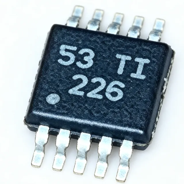
The Texas Instruments INA226AIDGSR-Q1 is an AEC-Q100 qualified, 36V, 16-bit current shunt and power monitor with an I2C- or SMBus-compatible interface, packaged in a 10-pin VSSOP (DGS). It measures both a shunt voltage drop (bidirectional, high-side or low-side) and bus supply voltage, then computes power, current, and energy with ultra-precise resolution. A current shunt and power monitor is a precision analog front-end placed across a series sense resistor; it belongs to the broader hierarchy of current sensing ICs, power management ICs, and semiconductor devices. By digitizing the microvolt-level shunt drop with a 16-bit delta-sigma ADC, it converts raw current into calibrated digital data that microcontrollers can read over I2C. Key features include a 16-bit ADC resolution for fine measurement granularity, a bus voltage monitoring range up to 36V, bidirectional shunt measurement enabling both charge and discharge tracking, a multi-function ALERT pin, and two address pins (A0, A1) supporting multiple devices on one I2C bus. Automotive AEC-Q100 qualification makes it suitable for vehicle environments. The architecture pairs a precision front-end with a programmable conversion-time and averaging engine, allowing engineers to trade conversion speed against noise performance. Register-based configuration permits calibration for specific shunt values, so current and power are reported in native units without host-side computation. Typical applications include automotive battery management systems, server and telecom power rails, solar/MPPT power monitoring, and industrial motor drive current sensing. In battery systems, the bidirectional measurement tracks both charging and discharging current through a single shunt. Design consideration: shunt resistor selection directly trades measurement resolution against power dissipation; keep the full-scale shunt drop within the input range while minimizing shunt loss at peak load.