Gestión de energía
Subcategorías
Productos (2819)

DRV8350SRTVT - 102V 3-Phase Smart Gate Driver WQFN-32 | TI
The Texas Instruments DRV8350SRTVT is a 102-V maximum three-phase smart gate driver for brushless DC (BLDC) motor applications, integrating three half-bridge gate drivers in a 32-pin WQFN (RTV) 5x5 mm package. It supports a wide operating supply range of 9 V to 100 V, drives external N-channel MOSFETs at up to 1 A peak gate-drive source / 2 A sink, and includes optional integrated buck regulator and triple low-side current shunt amplifiers. What is a three-phase smart gate driver? A three-phase smart gate driver is an integrated power-stage controller that converts low-power PWM logic signals from a microcontroller into high-current gate-drive signals for the three half-bridges of a three-phase BLDC or PMSM motor. It sits between the digital control domain (MCU + PWM) and the power domain (MOSFETs + motor windings) inside the power-management and motor-control IC hierarchy. The "smart" designation means the driver handles dead-time insertion, shoot-through protection, current sensing, and fault reporting autonomously, removing timing-critical tasks from the MCU. Key features include adjustable slew-rate control for EMI tuning, a VGS handshake mechanism that detects MOSFET readiness, integrated protection (UVLO, overcurrent, thermal shutdown, and gate-drive short protection), an SPI interface for configuration and telemetry, and an integrated 3.3V/5V buck regulator for auxiliary supply. The DRV8350S variant provides the SPI control interface, while the DRV8350H variant uses hardware pins. The DRV8350SRTVT uses a charge-pump architecture for the high-side gate supply that supports 100% duty-cycle operation. Triple low-side current-shunt amplifiers enable precise current sensing for Field-Oriented Control (FOC) and trapezoidal commutation. The device operates across -40C to +125C junction temperature and includes comprehensive fault diagnostics accessible via SPI status readback. Typical applications include cordless power tools (drills, saws, leaf blowers), e-bike and e-scooter traction drives, HVAC blower fans, robotic vacuum cleaners, small drones and BLDC pumps, and white-goods motor control. The SPI interface enables closed-loop tuning of gate-drive strength to balance EMI versus switching loss. When designing with the DRV8350SRTVT, ensure sufficient decoupling on VM (1 uF + 100 nF X7R), place gate-drive resistors close to the IC outputs, and use the integrated buck regulator for housekeeping supply. Drive strength is selectable via SPI, allowing the same BOM to cover 1 kW to 5 kW motor platforms. This page synthesizes distributor pricing, drop-in alternative cross-references, and practical design considerations not collated in the manufacturer datasheet, providing an engineering decision resource for selecting the DRV8350 family.
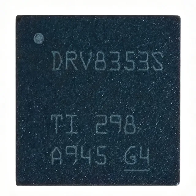
DRV8353SRTAR - 102V 3-Phase Smart Gate Driver | Texas Instruments
The Texas Instruments DRV8353SRTAR is a highly integrated three-phase smart gate driver designed for brushless DC (BLDC) motor applications. It operates from a supply voltage of 9V to 100V (102V absolute maximum) and is available in a 40-pin WQFN (RTA) package measuring 6x6 mm. This device integrates three half-bridge gate drivers, optional current shunt amplifiers, and an optional buck regulator, making it a compact solution for motor control systems. A smart gate driver is a specialized integrated circuit that controls the external power MOSFETs in a motor drive inverter. It translates low-voltage logic signals from a microcontroller into high-current gate drive signals, ensuring efficient and reliable switching of the power stage. The DRV8353 belongs to the DRV835x family, which is part of TI's motor driver portfolio, ultimately falling under power management ICs. This hierarchy places the device within the broader category of motor control and power conversion semiconductors. Key features of the DRV8353SRTAR include adjustable slew rate control for EMI performance, VGS handshake and dead-time management, and a SPI interface for configuration and diagnostics. The device supports a wide operating temperature range of -40°C to 125°C, making it suitable for industrial and automotive environments. The integrated current shunt amplifiers enable precise current sensing without external op-amps, reducing BOM cost and board space. Technically, the DRV8353 uses a smart gate drive architecture that monitors the gate-to-source voltage (VGS) to ensure proper turn-on and turn-off of the external MOSFETs. This reduces the risk of shoot-through and improves system reliability. The adjustable slew rate allows designers to optimize switching speed versus EMI, which is critical in noise-sensitive applications. The device also includes protection features such as undervoltage lockout (UVLO), overcurrent protection, and thermal shutdown. Typical applications include industrial motor drives, robotics, power tools, and automotive systems such as electric power steering and cooling fans. The wide input voltage range and integrated features make it ideal for both 12V and 48V systems. The SPI interface allows real-time monitoring and configuration, enabling advanced motor control algorithms. When designing with this device, ensure proper PCB layout with adequate copper pour for thermal dissipation, and place decoupling capacitors close to the power pins. The gate drive current and slew rate should be selected based on the external MOSFETs' gate charge to optimize switching performance.

DRV8353SRTAR-Q1 - 100V 3-Phase Smart Gate Driver SPI | TI
The Texas Instruments DRV8353SRTAR-Q1 is an AEC-Q100 qualified, 9-V to 100-V three-phase smart gate driver for BLDC and PMSM motors, housed in a 40-pin WQFN (RTA) 6x6 mm package and configurable via SPI. It integrates three half-bridge gate drivers with smart gate-drive architecture, adjustable slew-rate control, and optional triple low-side current shunt amplifiers for precise motor phase current sensing. A three-phase gate driver is a power-management IC that controls the external MOSFETs forming the three half-bridges of an inverter stage, providing the gate charge, protection, and control interface between an MCU and the power stage. Within the power hierarchy, it sits above discrete MOSFET drivers and below full motor-controller SoCs, bridging control electronics and the power stage. Key features include smart gate drive with VGS handshake and automatic handshake modes, IDRIVE current and slew-rate adjustability for EMI control, integrated 100% duty-cycle support and IVCP tri-level input, plus integrated protections: VDS overcurrent monitor, UVLO, OCP, OTS, and GDF fault reporting with SPI fault registers. The SPI interface enables full register-level configuration of gate-drive current, slew rate, and CSA gain. The smart gate-drive architecture allows engineers to tune MOSFET switching speed independently for turn-on and turn-off events, balancing EMI, efficiency, and di/dt-related protection. The on-chip current shunt amplifiers (programmable gain) enable low-side current sensing for FOC and trapezoidal control without external op-amps. Typical applications include automotive 48V BLDC pumps, fans, and traction auxiliaries, e-bike and power-sport motor inverters, industrial servo drives, drones, and power tools. The -40C to +125C operating range and AEC-Q100 qualification make it suited for harsh automotive environments. Design tip: size the IDRIVE setting to the external MOSFET gate charge to control switching slew; overly aggressive gate drive increases radiated EMI and VDS overshoot risk on the 100V rail.

DRV8376HQNLGRQ1 - Automotive 70V 4A BLDC Driver | TI
The Texas Instruments DRV8376HQNLGRQ1 is an automotive-grade, three-phase brushless-DC (BLDC) motor driver with integrated current sensing, designed for 4.5V to 65V motor supplies. It integrates three 1/2-H bridges with 70V absolute maximum capability and a very low RDS(on) of 400 mOhm (high-side plus low-side) to enable high-power drive capability, delivering up to 4A peak output current in a 28-pin VQFN (6x5mm) exposed-pad package operating from -40C to +125C. A motor driver is an integrated circuit that translates low-power control signals from a microcontroller into the high-current, high-voltage signals needed to drive a motor. The DRV8376-Q1 belongs to the gate driver and integrated power stage family, positioned between the MCU and the three-phase motor in the power electronics hierarchy. It provides the power amplification, current feedback, and protection layers required in modern automotive and industrial motion systems. Key features include integrated current sensing that eliminates external sense resistors, reducing BOM cost and board area. The device supports PWM control with a highly configurable interface through hardware pins or registers, allowing flexible current limiting, slew-rate control, and fault response tuning. Protection features include overcurrent, overtemperature, and undervoltage lockout with fault reporting, safeguarding the device, motor, and system. The DRV8376-Q1 uses an NMOS power-stage architecture in a three-phase bridge configuration. The low 400 mOhm RDS(on) minimizes conduction losses, improving thermal performance and efficiency. The integrated sense-FET current sensing provides accurate current feedback without the power loss of external shunts, enabling precise torque control and stall detection in FOC and trapezoidal control schemes. Typical applications include automotive BLDC motors such as electric power steering (EPS), engine cooling fans, oil pumps, and fuel pumps. AEC-Q100 qualification and the 4.5V to 65V input range suit both 12V and 24V automotive systems, as well as industrial drives and robotics requiring integrated sensing. When designing with this device, ensure proper PCB layout with adequate copper area on the VQFN exposed pad for thermal dissipation, and place decoupling capacitors close to the power pins. Calibrate the current-sense gain setting for accurate torque control.

DRV8426PWPR - 35V 1.5A Bipolar Stepper Driver | Texas Instruments
The Texas Instruments DRV8426PWPR is a 35-V, 1.5-A bipolar stepper motor driver with integrated current sensing and 1/256 microstepping, housed in a 28-pin HTSSOP (PWP) package with PowerPAD exposed thermal pad. It integrates two N-channel power MOSFET H-bridge drivers, a microstepping indexer, and integrated current-sense circuitry, eliminating the need for external sense resistors. The device accepts STEP/DIRECTION inputs and supports up to 1.5 A full-scale output current (PCB-dependent). A stepper motor driver is an integrated power stage which converts low-power logic-level step and direction signals into the high-current phase excitation waveforms required to commutate a two-phase bipolar stepper. Modern stepper drivers integrate the dual H-bridge power MOSFETs, gate drivers, current regulation loop, microstepping indexer, and protection features onto a single IC, reducing PCB area and BOM cost compared with discrete solutions. The DRV8426 belongs to the stepper driver / motor driver family, which sits under the broader power management IC category in the semiconductor taxonomy. Key features of the DRV8426PWPR include 1/256 native microstepping for smooth motion, internal current sensing that removes external sense resistors, an integrated charge pump for the high-side N-FET gate drive, and a low-power nSLEEP pin. The device also offers smart-tune ripple control and decay modes for adaptive current regulation, a fault indicator (nFAULT) output, and a wide 4.5 V to 35 V operating supply range. An internal voltage reference and digital indexer let the MCU control position with only step pulses. The DRV8426 uses a mixed-signal architecture: a digital control block interprets STEP/DIR and config registers while two H-bridge power stages deliver PWM-modulated current at up to 1.5 A per phase. Integrated current-sense comparators and the smart-tune decay algorithm minimize torque ripple and audible noise, achieving smoother motion than fixed-decay competitors. The exposed thermal pad on the HTSSOP-28 package keeps theta_JA low for sustained 1.5-A operation on moderate copper pours. Typical applications include 3D printers, CNC machines, robotic vacuum cleaners, textile machines, office automation equipment, and small-format industrial stepper drives. The wide 35-V input range comfortably handles 24-V industrial bus supplies with transient headroom. When designing with the DRV8426PWPR, observe TI's PCB layout guidelines for the HTSSOP PowerPAD: stitch the EP to a ground copper pour with multiple thermal vias, place VM decoupling capacitors within 5 mm of the VM pins, and keep the high-current motor traces short and wide. Verify the chosen motor's phase inductance is within the smart-tune ripple-control tuning range, or use the fixed-decay modes if motor acoustics are problematic. This page synthesizes distributor pricing, drop-in alternatives, and practical design notes not found in the manufacturer datasheet, giving engineers an actionable reference for selecting and laying out the DRV8426PWPR.
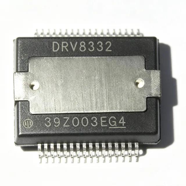
DRV8432DKDR - 52V 14A Dual Full-Bridge Motor Driver | TI
The Texas Instruments DRV8432DKDR is a high-performance, integrated dual full-bridge PWM motor driver designed for driving DC motors, stepper motors, and other inductive loads. It operates from a load supply voltage of 0 V to 52.5 V and can deliver up to 14 A continuous output current per bridge (7 A per channel in dual full-bridge mode). The device is housed in a 36-pin HSSOP (PowerPAD) package, providing excellent thermal performance for high-power applications. A motor driver is an integrated circuit that translates low-power control signals from a microcontroller or DSP into high-current, high-voltage signals capable of driving motors. The DRV8432 belongs to the motor driver category, which is a subset of power management ICs. It integrates four half-bridges (configurable as two full H-bridges) with low RDS(on) MOSFETs (110 mΩ at TJ = 25°C), achieving up to 97% power-stage efficiency. This integration reduces external component count and simplifies PCB layout compared to discrete H-bridge designs. Key features include advanced protection circuitry: overcurrent protection (OCP), overtemperature protection (OTP), undervoltage lockout (UVLO), and overvoltage protection (OVP). The device supports PWM control with a wide frequency range, and its current regulation capability enables precise torque control in stepper applications. The DRV8432 also features a sleep mode for low-power standby, reducing quiescent current consumption. Technically, the DRV8432 uses a bootstrap-based gate drive architecture for the high-side N-channel MOSFETs, requiring external bootstrap capacitors. The device provides separate logic and power grounds, and its digital inputs are compatible with 3.3 V and 5 V logic levels. The PWM frequency can be set up to 500 kHz, making it suitable for high-speed switching applications. The thermal pad on the HSSOP package must be soldered to a copper plane for adequate heat dissipation. Typical applications include brushed DC motor drivers in robotics, industrial automation, and automotive systems; bipolar stepper motor drivers in 3D printers and CNC machines; and solenoid drivers in vending machines and industrial controls. The wide voltage range and high current capability make it versatile for various motor control systems. When designing with the DRV8432, ensure proper PCB layout with low-inductance paths for high-current loops and adequate thermal vias under the thermal pad. The bootstrap capacitors should be placed close to the respective pins, and the logic supply should be decoupled with a 0.1 µF ceramic capacitor.

DRV8434ARGER - 48V 2.5A Stepper Driver w/ Stall Detect | TI
The Texas Instruments DRV8434ARGER is a 48-V, 2.5-A bipolar stepper motor driver with integrated current sensing, 1/256 microstepping, Smart Tune, and stall detection via GPIO pins, housed in a 24-pin VQFN (RGE) 4x4 mm package. The device integrates two H-bridge NMOS output stages with internal current-sense resistors, removing the need for external sense resistors and shrinking the BOM for space-constrained designs. What is a bipolar stepper motor driver? A bipolar stepper motor driver is an integrated H-bridge circuit that drives the two coils of a two-phase bipolar stepper motor by reversing current flow through each coil on every step. It sits within the broader hierarchy: motor driver -> motion control -> power management IC -> semiconductor. The DRV8434A family adds integrated current sensing (using an internal sense FET), microstepping indexer (up to 1/256 step), and stall detection - features historically requiring external comparators, ADCs, and an MCU. Key features include a 4.5 V to 48 V wide operating supply range, 2.5 A full-scale output current per H-bridge, 1/256 microstepping indexer, Smart Tune decay mode (mixed decay), integrated current sensing (no external sense resistor required), stall detection output on a GPIO pin, and a low-power nSLEEP pin. Protection features include supply undervoltage, charge pump fault, overcurrent, short circuit, open load, and overtemperature shutdown, with faults flagged on the nFAULT pin. The DRV8434ARGER uses TI's Smart Tune technology that dynamically adjusts the fast-decay portion of each PWM cycle to minimize current ripple and audibility. The integrated current-sense path eliminates the bulky external sense resistor and its associated power dissipation, allowing tighter PCB layouts in compact camera gimbals, medical pumps, and small-format 3D printers. Typical applications include 3D printers (extruder and bed motors), security cameras and PTZ platforms, textile and sewing machines, medical infusion pumps, and factory automation stages. The wide 48 V input supports industrial 24 V and 36 V bus rails with margin for inductive transients. When designing with this part, place the VM and VINT bypass capacitors as close as possible to the pins and follow TI's recommended 4-layer thermal layout for the RGE package. The stall detection GPIO must be configured via SPI to avoid false triggers during acceleration ramps - see the device datasheet for the recommended configuration sequence. This page synthesizes distributor pricing, drop-in alternatives from the same DRV8434 family, and practical PCB layout notes not found on the manufacturer product page alone.

DRV8434ERGER - 48V 2.5A Dual H-Bridge Motor Driver | Texas Instruments
The Texas Instruments DRV8434ERGER is a 48-V, 2.5-A dual H-bridge motor driver with integrated current sensing, Smart Tune technology, and 1/256 microstepping indexer, housed in a 24-pin VQFN (4x4) RGE package. It is designed to drive one bipolar stepper motor or two brushed DC motors in industrial and consumer motion-control applications where compact PCB footprint, accurate current regulation, and low RDS(on) are essential. According to the TI DRV8434E datasheet, the device integrates four N-channel power MOSFETs in two full H-bridges, eliminating the need for external power switches. What is a dual H-bridge motor driver? A dual H-bridge motor driver is an integrated power IC that contains two complete H-bridge output stages on one die, each capable of switching current bidirectionally through a DC motor winding. Two H-bridges together can drive one bipolar stepper (four-wire) motor, one BLDC motor with external commutation logic, or two independent brushed DC motors. The H-bridge topology sits within the broader category of motor driver ICs, which are themselves a sub-category of power management semiconductors. Compared to discrete MOSFET H-bridges, integrated drivers add on-chip current sensing, PWM control logic, fault protection, and (in this case) an integrated microstepping indexer. Key features of the DRV8434ERGER include: 4.5 V to 48 V wide operating supply range, 2.5 A full-scale output current per H-bridge with internal current-sense amplification, programmable decay modes (Smart Tune, Slow, Mixed, Fast), 1 to 1/256 native microstepping without external logic, and a dedicated nSLEEP pin for low-power standby. The Smart Tune decay algorithm automatically selects between slow and fast decay to minimize ripple current and audible noise, a key benefit for office automation and home appliance designs. Technically, the DRV8434E family uses a charge-pump-generated gate drive for the high-side N-FETs, eliminating the need for a bootstrap capacitor. The integrated current sense uses an internal sense-FET topology, removing the external sense resistor and shrinking the BOM. STEP/DIR inputs allow simple host-MCU control of position, while off-the-shelf step rates from full-step to 1/256 microstep are selectable via the M0/M1 pins. Typical applications include 3D printers, CNC routers, textile and sewing machines, office automation (printers, scanners, copiers), ATM and POS cash handlers, video surveillance PTZ cameras, factory automation stages, and any small bipolar stepper or dual brushed DC motor up to 2.5 A per winding. The DRV8434ERGER is also suitable for battery-powered robotics using two brushed DC motors. When designing with this part, choose bulk input capacitance (at least 47 uF) sized for the worst-case motor back-EMF, and connect the exposed thermal pad to a continuous ground copper pour. Configure decay mode to Smart Tune Ripple Control for most stepper loads to minimize audible noise and torque ripple.
DRV8434RGER - 48V 2.5A Stepper Driver VQFN-24 | Texas Instruments
The Texas Instruments DRV8434RGER is a 48-V, 2.5-A bipolar stepper motor driver with integrated current sensing, 1/256 microstepping indexer, and STEP/DIRECTION interface, housed in a 24-pin VQFN (RGE) package measuring 4x4 mm. It integrates two N-channel power MOSFET H-bridges plus a smart-tune mixed-decay current regulator, eliminating the need for external sense resistors while preserving microstep accuracy. A stepper motor driver is an integrated power stage that converts low-level STEP and DIR logic signals from a microcontroller into the high-current, sequenced phase currents required to commutate a two-phase bipolar stepper. The DRV8434 belongs to the broader stepper-driver family within motor-driver ICs, which themselves sit under the power-management umbrella alongside DC-DC converters, gate drivers, and motor predrivers. Bipolar operation means each phase winding is driven by a true H-bridge so current can flow in both directions through the coil. Key features include a wide 4.5-V to 48-V motor supply range, 2.5-A full-scale output per H-bridge with internal current sensing (no external shunt), 1/256 microstepping for smooth motion, an internal 3.3-V reference for logic-level setting, smart-tune technology that auto-adjusts decay mode, and ultra-low 2-uA sleep-mode quiescent current. SPI programmability is also available on the E-variant family for tuning microstep, decay, torque, and fault response. The architecture combines a charge-pump gate supply, dual H-bridge with integrated 330-mOhm HS+LS FETs (per the related DRV8424 family data), configurable off-time PWM chopping (7, 16, 24, or 32 microseconds), and spread-spectrum clocking for reduced EMI. Internal protection includes VM undervoltage lockout, charge-pump fault, overcurrent, overtemperature, and open-load detection. The RGE package exposes a thermal pad for low thermal resistance. Typical applications include textile and sewing machines, CCTV cameras and pan-tilt-zoom stages, 3D printers, robotic vacuum cleaners, point-of-sale printers, and any 24-V or 36-V nominal bipolar stepper subsystem where PCB area, BOM count, and smooth motion matter. The device operates across -40C to +125C junction temperature, suiting industrial environments. When designing with this part, place the VM bulk capacitors as close as possible to the pins and keep the exposed thermal pad soldered to a continuous ground copper pour. Verify that the chosen motor's phase inductance is above the driver minimum to avoid excessive ripple current at high step rates. This page synthesizes distributor pricing, drop-in alternates, and design notes not found in the manufacturer datasheet, giving engineers a faster path from selection to validated BOM.

DRV8714SQRHARQ1 - 40V 4-Ch Smart Gate Driver | TI | Automotive
The Texas Instruments DRV8714SQRHARQ1 is an automotive-grade, 40-V, four-channel half-bridge smart gate driver with integrated wide common-mode inline current sense amplifiers, housed in a 56-pin VQFN (RVJ) package. A half-bridge gate driver is a power-management IC that controls the gate charge of external MOSFETs in an H-bridge or half-bridge power stage. It sits between a low-voltage controller (MCU) and the power FETs, translating logic-level PWM signals into gate-drive currents while providing protection, dead-time management, and current feedback. Multi-channel gate drivers such as the DRV871x-Q1 family consolidate driver power supplies, shunt amplifiers, and protection monitors into one IC, replacing dozens of discrete components in a brushed-DC, stepper, or solenoid drive stage. Key features include a 40-V operating rating suitable for 12-V and 24-V automotive battery systems with load-dump headroom, four independently controllable half-bridges, and smart gate-drive architecture that automatically manages dead time to minimize switching losses and shoot-through. Integrated wide common-mode inline current sense amplifiers eliminate external shunt amplifiers and support accurate motor current feedback for FOC and stall detection. The DRV871x-Q1 family integrates driver power supplies, current shunt amplifiers, and protection monitors, reducing total system complexity, size, and cost. Per the TI datasheet, the DRV8718-Q1 (8-channel) and DRV8714-Q1 (4-channel) are drop-in pin-to-pin compatible in the 56-pin VQFN (RVJ) package, with half-bridge 1-4 locations shifted on the DRV8714-Q1 to aid PCB routing. Typical applications include automotive brushed DC motor control for pumps, fans, dampers and actuators, solenoid drivers, seat adjusters, and multi-motor body-electronics modules requiring AEC-Q100-qualified silicon. Design consideration: verify gate-drive current settings and dead-time register configuration in SPI before first power-up, and place gate-loop layouts short and symmetrical to limit ringing. This page synthesizes distributor pricing, drop-in alternative data, and practical design notes not found in the manufacturer datasheet.
DRV8718SQRHARQ1 - 40V 8-Ch Half-Bridge Gate Driver | Texas Instruments
The Texas Instruments DRV8718SQRHARQ1 is an automotive-qualified, 8-channel half-bridge smart gate driver with wide common-mode inline current sense amplifiers, operating from a 4.9 V to 37 V supply range (40 V absolute maximum) in a 56-pin VQFN (8x8 mm) package. A half-bridge gate driver is a power management IC that controls the gate terminals of external power MOSFETs, allowing a low-voltage logic controller to switch high-current motor loads safely and efficiently. Within the power-delivery hierarchy, it sits between the microcontroller and the power stage: gate driver -> power stage -> motor/load driver -> power management IC. The DRV871x-Q1 family integrates multiple half-bridge drivers, driver power supplies, current shunt amplifiers, and protection monitors to reduce total system complexity, size, and cost. Key features include AEC-Q100 qualification at temperature grade 1 (-40C to +125C ambient), pin-to-pin 4-channel (DRV8714-Q1) and 8-channel (DRV8718-Q1) variants, 4 PWM inputs with flexible output mapping, and a tripler charge pump that sustains 100% duty-cycle PWM operation. Integrated wide common-mode inline current sense amplifiers eliminate the need for external amplifiers in brushless DC motor control. Architecturally, the DRV8718SQRHARQ1 integrates eight half-bridge gate drivers with internal gate-drive supplies and per-channel protection (overcurrent, OVP/UVP, thermal shutdown), making it suited to 12 V and 24 V automotive battery rails with load-dump headroom. Smart gate-drive features tune MOSFET switching to control EMI while limiting switching loss. Typical applications include automotive DC motor control (pumps, fans, actuators), body electronics modules, HVAC dampers, and general-purpose multi-motor loads driven by external power MOSFETs. Design consideration: choose external MOSFETs whose gate charge matches the drive capability of each channel, and route high-current paths away from the current-sense amplifier inputs to preserve accuracy. This page synthesizes verified distributor data, same-family drop-in alternatives, and practical design notes not found in the manufacturer datasheet.

DRV8804PWPR - 65V 2.3A Quad Low-Side Driver | Texas Instruments
The Texas Instruments DRV8804PWPR is a 65 V, 2.3 A quad-channel low-side driver with integrated SPI control and per-channel overcurrent protection, housed in a 16-pin HTSSOP (PWP) package with PowerPAD. The device integrates four N-channel MOSFETs with a typical RDS(on) of 500 mΩ, built-in inductive catch diodes, and a daisy-chainable serial interface that allows multiple drivers to share a single SPI bus. A low-side driver is a switching topology where the load is tied to a positive supply and the driver transistor pulls the load to ground to energize it. Compared to high-side or H-bridge drivers, low-side drivers are simpler, lower-cost, and well suited to unipolar loads where current direction is fixed. The DRV8804 belongs to the broader category of motor and motion driver ICs, which sit between a microcontroller and electromechanical loads such as stepper motors, DC motors, relays, and solenoids. It supports unipolar stepper drive, brushed DC motor drive, and generic low-side switching. Key features include a wide 8.2 V to 60 V operating range, integrated clamping diodes for inductive transient suppression, parallelable outputs for higher current, and individual channel enable and fault reporting through SPI. The device also provides thermal shutdown, undervoltage lockout, and an open-drain fault output to flag overcurrent events to the host controller. Typical applications include unipolar stepper motor drives (one coil at a time), brushed DC motor drivers, relay and solenoid arrays, valve and actuator control, and LED string driving in industrial and building-automation systems. The HTSSOP-16 PowerPAD package enables sustained 1.5 A per-channel operation with proper PCB thermal design. When designing with this device, ensure the PowerPAD is soldered to at least 1 sq. in. of copper to keep junction temperature within the 150 C limit, and add a bulk capacitor at VM to absorb motor back-EMF. The SPI interface requires proper CS framing and clock polarity consistent with the datasheet timing diagram.

DRV8806PWPR - 40V 3A Quad Low-Side Motor Driver | TI
The Texas Instruments DRV8806PWPR is a 40 V, 3 A quad-channel low-side driver with integrated SPI and open-load detection, housed in a 16-pin HTSSOP (PWP) package with PowerPAD. It provides four protected low-side DMOS outputs that can deliver up to 2 A continuous per channel (3 A peak) and is primarily intended to drive unipolar stepper motors, DC motors, solenoids, and relays from a single supply rail. A low-side motor driver is a topology where each output transistor pulls the load terminal to ground, while the opposite end of the load remains tied to the supply. In the broader power-management taxonomy, the DRV8806 sits within motor drivers and gate drivers, which themselves belong to the power-management IC family. Compared with full H-bridge drivers, low-side drivers are simpler, cheaper, and easier to parallel, but they require the load to be tied to the supply externally and cannot actively brake by sourcing current into the rail. Key features include four independent DMOS outputs with 200 mOhm RDS(on) typical, integrated freewheeling clamp diodes for inductive loads, configurable overcurrent protection per channel, open-load detection through the SPI interface, thermal shutdown, and undervoltage lockout. The SPI port exposes fault status, control bits, and PWM duty-cycle registers, allowing a host MCU to manage current limiting and diagnose wiring faults without extra analog circuitry. The device operates from 8.2 V to 38 V on VM and is controlled through a 3.3 V-compatible SPI bus. Internal charge-pump-derived gate drive keeps the low-side FETs fully enhanced across the full supply range, while the on-chip current-sense comparator supports PWM current chopping for stepper or solenoid actuation. A fault output pin flags overtemperature, overcurrent, and open-load events to the host. Typical applications include unipolar stepper motor indexing, inkjet and label printer carriage control, solenoid and valve drivers, relay arrays, and low-voltage DC brush motor actuation. The wide 8.2 V to 38 V supply range covers 12 V and 24 V industrial buses, making the part attractive for factory automation boards. When laying out the PCB, solder the exposed PowerPAD to a continuous ground copper pour to keep junction temperature within ratings; without this thermal path the package cannot dissipate the full 3 A per channel. Bypass VM with a 100 nF ceramic plus a 47 uF or larger bulk capacitor placed within 5 mm of the supply pin to suppress the high di/dt transients that occur during PWM chopping. This page consolidates distributor pricing, drop-in alternatives, and design notes that go beyond the manufacturer datasheet to help engineers shorten their selection and qualification cycle.
DRV8814PWPR - 47V 2.5A Dual Brushed DC Motor Driver | TI
The Texas Instruments DRV8814PWPR is a 47-V, 2.5-A dual brushed DC motor driver with integrated inrush protection, housed in a 28-pin HTSSOP (PWP) package with PowerPAD. It operates from an 8 V to 45 V supply and provides two independent H-bridge channels that can each deliver up to 2.5 A of continuous drive current at 24 V and TA = 25 °C, making it well-suited to printers, scanners, robotic actuators, and other automated equipment. A dual H-bridge motor driver is a power IC that integrates four power MOSFET switches and their control logic into one package so a microcontroller can command direction, brake, coast, and PWM-based current regulation on two DC motors (or one bipolar stepper) from a single supply rail. These devices sit in the broader hierarchy of motor control IC -> motion control -> power management, and the DRV8814 family is part of TI's brushed-DC driver portfolio distinguished by integrated current-sense and parallel interface control. Key features of the DRV8814PWPR include four-level winding current control, multiple decay modes (slow decay, fast decay, and mixed decay), a PHASE/EN parallel interface for direction and enable, an internal inrush current limiter that protects the supply rail at startup, and built-in protection features including overcurrent protection (OCP), thermal shutdown (TSD), undervoltage lockout (UVLO), and fault-current reporting via the FLT pin. The HTSSOP-28 PowerPAD package delivers a low thermal resistance of approximately 31 °C/W (junction-to-case), enabling continuous 2.5 A operation with moderate PCB copper area. The parallel control scheme allows four discrete control inputs, simplifying host-firmware logic and reducing MCU timer overhead compared to PWM-only stepper interfaces. The DRV8814PWPR is typically used in printers, scanners, robotic actuators, automated teller machines, textile machinery, and office automation. Its 45-V absolute-maximum supply tolerance also makes it compatible with 24-V and 36-V industrial bus rails. The DRV8841 and DRV8843 are related TI parts but use different interfaces and are not drop-in compatible. This page synthesizes distributor pricing, drop-in same-package alternatives, parametric tables, and practical design notes not consolidated on the manufacturer product page.
DRV8816PWP - 40V Dual Half-H Bridge Motor Driver | Texas Instruments
The Texas Instruments DRV8816PWP is a 40-V, dual 1/2-H-bridge DMOS motor driver that integrates two independent half-H-bridge output stages into a single 16-pin HTSSOP (PWP) package with PowerPAD. Each output stage uses N-channel power MOSFETs configured as a half-H bridge, and a simple INx/ENx interface allows easy connection to a host controller for brushed DC motors, stepper motor windings, solenoids, relays, and other inductive loads. The device accepts supply voltages from 8 V to 38 V and can deliver up to 2.8 A peak per output, making it a flexible power stage for medium-current motion and actuation subsystems. Background Knowledge: A 1/2-H-bridge motor driver is a power-management integrated circuit that contains two switching MOSFETs (a high-side and a low-side device) and the gate-drive logic to control them in a push-pull fashion. Two half-H bridges can be combined externally to build a full H-bridge for bidirectional DC motor or bipolar stepper winding control. The DRV8816 family belongs to the broader category of integrated motor drivers, which sit inside the power-management IC hierarchy and replace discrete MOSFET gate-drive circuits to save board area, simplify firmware, and add on-chip current limiting. Key features include built-in shoot-through protection, integrated current-sense feedback for current control loops, undervoltage lockout (UVLO), and thermal shutdown with fault-flag indication. The device operates over a -40 C to +85 C ambient range and is offered in a thermally enhanced HTSSOP-16 (PWP) package with an exposed thermal pad that lowers theta_JA and enables continuous high-current operation with a moderate PCB copper pour. A parallel-interface architecture lets two independent outputs share logic pins without SPI overhead, which simplifies firmware and reduces controller pin count compared to multi-channel serial PMIC interface topologies. Architecturally, the DRV8816 uses DMOS output transistors with low on-resistance, which reduces thermal losses at high peak currents. The integrated charge pump supplies the high-side gate drive, and a programmable blanking time suppresses false current-sense trips caused by diode reverse recovery. This makes the device suitable for fast-switching PWM control up to 200 kHz with predictable current-limit behavior across motor and solenoid loads. Typical applications include brushed DC motor drivers, bipolar stepper motor winding drivers, solenoid and valve drivers, LED string drivers, and generic half-H-bridge actuator stages. Two DRV8816 channels can be wired together externally to form a single full H-bridge for one bipolar stepper motor (single-axis), or two channels can each drive an independent brushed DC motor, solenoid, or relay. The wide 8 V to 38 V supply range covers both 12 V and 24 V industrial bus rails. When designing with the DRV8816PWP, observe the thermal limits: at 2 A per channel continuous with both channels active, dissipation can exceed 2 W and requires the exposed pad to be soldered to a copper pour of at least 1 square inch. Always respect the absolute-maximum supply of 40 V and add a bulk reservoir capacitor near the VM pin to absorb motor back-EMF. This page synthesizes distributor pricing, drop-in alternatives, and practical PCB thermal guidance not found in the manufacturer datasheet alone, giving engineers a single source for sourcing and second-source-equal-cross-reference decisions on the DRV8816 half-H-bridge family.

DRV8818PWPR - 2.5A Bipolar Stepper Motor Driver | TI
The Texas Instruments DRV8818PWPR is a bipolar stepper motor driver with integrated current regulation and microstepping indexer, capable of driving up to 2.5 A per winding. It operates from a supply voltage range of 8 V to 35 V and is housed in a 28-pin HTSSOP (PWP) package with an exposed thermal pad (PowerPAD). The device integrates two H-bridge drivers and a microstepping indexer that supports up to 1/8-step operation, making it suitable for printers, scanners, textile machines, and other automated equipment. A stepper motor driver is a power management IC that translates step and direction signals into the precise current sequences needed to rotate a stepper motor. It typically includes H-bridge output stages, current sensing, and protection features. The DRV8818 belongs to the motor driver category, which is part of the broader power management IC family. It uses a STEP/DIR interface, simplifying the connection to a microcontroller or motion controller. Key features of the DRV8818PWPR include a low 0.37 Ω (HS + LS) MOSFET on-resistance at 25°C, which minimizes power dissipation and improves efficiency. The device supports programmable mixed decay, blanking time, and off time, allowing designers to optimize current regulation for different motor types and operating conditions. It also provides a separate logic supply voltage (VCC) for the digital interface, enabling operation with 3.3 V or 5 V logic while the motor supply can be up to 35 V. The DRV8818 uses a current-regulation architecture with a built-in indexer that generates the microstepping waveforms. The device includes protection features such as overcurrent, overtemperature, and undervoltage lockout. The low on-resistance and high current capability make it suitable for applications requiring smooth motion and low heat generation. Typical applications include 3D printers, office automation equipment, vending machines, and industrial automation. The device's wide supply range and robust output stage allow it to drive a variety of bipolar stepper motors. The HTSSOP-28 package with PowerPAD provides excellent thermal performance, enabling continuous operation at high currents with proper PCB layout. When designing with the DRV8818, ensure adequate decoupling on the motor supply and logic supply pins. The exposed thermal pad must be soldered to a copper plane for heat dissipation. The STEP/DIR inputs should be filtered to avoid noise-induced false steps.
DRV8825PWPR - 45V 2.5A Stepper Motor Driver | TI
The Texas Instruments DRV8825PWPR is a bipolar stepper motor driver with integrated current regulation and 1/32 microstepping, delivering up to 2.5A output current (with proper thermal design) in a 28-pin HTSSOP (PWP) package. It operates from a supply voltage of 8.2V to 45V, making it suitable for a wide range of industrial and consumer motion control applications. A stepper motor driver is a power management IC that translates step and direction signals into the precise current sequences needed to drive a bipolar stepper motor. It integrates two H-bridges and a microstepping indexer, simplifying the interface between a microcontroller and the motor. The DRV8825 belongs to the motor driver category, which is part of the broader power management IC family. Key features include 1/32 microstepping, which provides smooth motion and reduced noise, and current regulation that maintains constant torque regardless of motor speed. The device also includes protection features such as overcurrent, overtemperature, and undervoltage lockout, ensuring reliable operation in demanding environments. The nFAULT pin provides fault indication to the host controller. The DRV8825 uses a power MOSFET architecture with low on-resistance, minimizing power dissipation and improving efficiency. The microstepping indexer generates the necessary current waveforms, reducing the computational load on the microcontroller. The device supports both step/direction and phase/enable interfaces, offering flexibility in system design. Typical applications include 3D printers, CNC machines, robotics, and automated equipment such as printers and scanners. The wide voltage range and high current capability make it ideal for driving NEMA 17 and NEMA 23 stepper motors. The HTSSOP package with exposed thermal pad facilitates heat dissipation, enabling continuous operation at moderate currents. When designing with the DRV8825, ensure adequate PCB copper area for thermal management, especially at currents above 1.5A. Place the sense resistors close to the device and use proper decoupling capacitors on the VM pin to minimize voltage spikes.
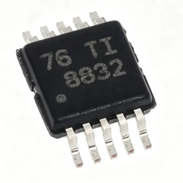
DRV8832DGQR - 1A H-Bridge Motor Driver 6.8V | Texas Instruments
The Texas Instruments DRV8832DGQR is a 1 A low-voltage H-bridge motor driver with integrated voltage regulation, operating from a 2.75 V to 6.8 V supply and housed in a 10-pin HVSSOP (DGQ) package with exposed thermal pad. An H-bridge motor driver is a power management IC that controls the direction and speed of a DC motor by selectively energizing four power transistors arranged in an H configuration. It sits between a low-power microcontroller and the motor winding, translating logic-level control signals into high-current drive. Within the semiconductor hierarchy, the DRV8832 belongs to the motor driver family under power management ICs, complementary to voltage regulators and gate drivers in motion-control signal chains. Key features include a high-efficiency power stage built from N-channel and P-channel power MOSFETs with low RDS(on), achieving up to 97% efficiency. The integrated voltage-regulation loop maintains a stable effective motor voltage, improving speed regulation directly from a discharging battery. A current-limit function regulates winding current during motor start-up or stall, and a dedicated nFAULT output pin signals fault conditions to a host processor. Technically, the DRV8832 provides one H-bridge controlled by IN1 and IN2 logic inputs, capable of driving one brushed DC motor, one winding of a stepper motor, or other loads such as solenoids. Protection includes thermal shutdown and undervoltage lockout (UVLO) for robust field operation. The tiny 3 mm x 3 mm package supports compact, battery-powered layouts, and the device is offered in eco-friendly RoHS-compliant construction without Sb/Br. Typical applications include battery-powered toys, printers, and other portable motion-control products, where its wide 2.75 V to 6.8 V supply range tracks battery discharge directly, plus small-appliance actuators and solenoid drivers. When designing with this device, provide adequate PCB copper under the exposed thermal pad for heat dissipation at sustained 1 A loads, and place decoupling capacitors close to the supply pins to minimize voltage transients during PWM switching. This page synthesizes distributor pricing context, verified drop-in alternatives, comparison data, and practical design notes not found in the manufacturer datasheet alone.

DRV8832DRCR - 6.8V 1A H-Bridge Motor Driver | Texas Instruments
The Texas Instruments DRV8832DRCR is a 6.8V, 1A H-bridge brushed DC motor driver IC with integrated current regulation, housed in a 3-mm x 3-mm 10-pin VSON (DRC) package. It integrates the power MOSFETs, gate drive, current-limit circuitry, and fault reporting needed to drive one brushed DC motor or one winding of a stepper motor from a single low-voltage supply. An H-bridge motor driver is a power management IC that uses four switching transistors arranged in an H configuration to reverse the polarity of the voltage applied to a motor, enabling forward, reverse, brake, and coast (hi-Z) operation. Within the system hierarchy, motor drivers sit between a host controller (MCU or logic) and the motor itself, translating low-current logic commands into high-current motor drive while providing protection features such as current limiting, undervoltage lockout, and thermal shutdown. Key features include a wide operating supply range for battery-powered designs, a fixed off-time PWM current-regulation scheme that limits motor current during start-up or stall conditions, a low-power sleep mode that reduces supply current to conserve battery life, and an nFAULT output pin that signals fault conditions to a host processor. The integrated MOSFETs deliver up to 1A of continuous output current without external discrete transistors. The DRV8832 architecture uses internal gate drive and voltage regulation so that only the motor supply and logic inputs are required externally - no external bootstrap components or gate-drive circuitry are needed. The internal current-limit regulation repeatedly disables and re-enables the bridge at a fixed off-time when the set current threshold is exceeded, holding motor torque under control during stall or acceleration events and protecting both the IC and the motor windings. Typical applications include battery-powered toys, printers, and other low-voltage or battery-powered motion control products such as small actuators, camera lenses, locks, and consumer robotics. The low minimum supply voltage suits single-cell or dual-cell battery stacks, and the tiny 3x3 mm footprint suits space-constrained mechanisms in printers and portable devices. A key design consideration is thermal management: at high load currents the VSON-10 package relies on its exposed pad soldered to a copper pour on the PCB to dissipate heat. Verify that the continuous motor current and the on-resistance of the internal MOSFETs keep junction temperature within limits over the full ambient range. This page synthesizes verified distributor data, TI product information, drop-in alternative analysis, and practical design notes not found in the manufacturer datasheet, providing an engineering-ready reference for the DRV8832DRCR.

DRV8837DSGR - 12V 1.8A H-Bridge Motor Driver | Texas Instruments
The Texas Instruments DRV8837DSGR is a 12 V, 1.8 A low-voltage H-bridge motor driver with PWM control, housed in an 8-pin WSON (DSG) package. It is designed to drive a brushed DC motor, one winding of a stepper motor, solenoids, or other bidirectional loads from battery-powered systems. Its integrated interface uses IN1 and IN2 inputs for direction and PWM control, while internal shutdown functions provide overcurrent, short-circuit, undervoltage-lockout, and overtemperature protection. An H-bridge motor driver is a power-management semiconductor that uses four MOSFET output switches to reverse current through a load and regulate its speed. The DRV8837 belongs to the motor-driver and power-management IC hierarchy, combining a control input stage, N-channel power MOSFETs, an H-bridge power stage, and integrated protection in one compact device. This makes it suitable for compact motion systems where a discrete MOSFET bridge would require more board area and additional protection circuitry. The DRV8837DSGR provides a maximum drive current of 1.8 A and is identified as a 12 V H-bridge motor driver. Its PWM interface supports speed control, while the IN1-IN2 logic determines drive direction. Internal shutdown functions are specified for overcurrent protection, short-circuit protection, undervoltage lockout, and overtemperature conditions. The device is intended for low-voltage or battery-powered motion-control applications such as cameras, consumer products, toys, and other compact motorized equipment. The WSON (DSG) package has 8 pins and is specified for surface mounting. Its compact package helps reduce PCB footprint, but thermal performance and exposed-pad layout remain important at sustained high motor current. The motor and wiring environment can introduce electrical noise, inductive transients, and large current loops, so power-loop layout, grounding, bulk capacitance, and protection must be designed together. The manufacturer product page and distributor records are the primary sources for current package, ordering, and lifecycle information. Typical applications include small camera positioning mechanisms, battery-operated toys, consumer appliances, compact fan or pump controls, solenoid actuation, and low-voltage stepper-motor winding drives. For these applications, the DRV8837 provides bidirectional control and integrated fault handling, reducing the number of external power transistors and support components. The main design trade-off is that the motor's supply voltage, stall current, wiring inductance, and thermal conditions must remain within the device's verified operating limits. This page combines verified Texas Instruments product information, distributor search results, package details, application guidance, and a strict drop-in alternative review. The DRV8837DSGR is listed with an 8-pin WSON DSG package and an operating temperature range of -40 to 85 in the verified product-page snippet. Confirm the complete electrical limits, pin functions, exposed-pad requirements, and protection behavior against the current manufacturer datasheet before releasing a production design.
DRV8847PWPR - 18V 2A Dual H-Bridge Motor Driver | Texas Instruments
The Texas Instruments DRV8847PWPR is an 18-V, 2-A dual H-bridge motor driver with integrated power MOSFETs, current regulation, and independent half-bridge control, housed in a 16-pin HTSSOP (PWP) package with PowerPAD exposed thermal pad. It is designed to drive two dc brushed motors, a bipolar stepper motor, relays, solenoids, or other mechatronic loads from a single 0 to 11-V (absolute max 18-V) power supply. An H-bridge motor driver is a type of brushed dc or stepper motor driver that uses four switching elements arranged in an H configuration to apply voltage to a motor winding in either polarity. The dual H-bridge architecture used in the DRV8847 sits within the broader motor driver hierarchy: motor driver -> H-bridge -> half-bridge -> power management IC -> semiconductor. Independent half-bridge control allows each of the four low-side and high-side FETs to be addressed separately, enabling advanced commutation schemes, current-mode regulation, and parallel MOSFET control when higher drive current is required. Key differentiating specifications include a low 7.5-mA (typical) quiescent current, integrated current-sense with chopping regulation at 5 A peak per H-bridge, built-in 1.5-A continuous output current per H-bridge (with proper PCB thermal design), independent INx/ENx logic interface per half-bridge, automatic dead-time generation, and overtemperature/overcurrent/undervoltage protection. The integrated protection is proprietary to the DRV8847 and removes several discrete parts that a discrete H-bridge design would need. Technically, the device uses N-channel power MOSFETs in each half-bridge with internal charge pump to drive the high-side gates, allowing 100% duty cycle operation. The internal current-shunt amplifier with external reference (VREF) supports both fixed off-time and PWM current chopping, enabling precise torque control in stepper or brushed-dc applications. Typical applications include industrial automation (small stepper indexers, valve actuators, ePOS printers), home appliances (small pumps, fans, latches, dispenser valves), robotics and toys (low-voltage brushed dc gearmotors), and office equipment (paper feeders, scanners). The HTSSOP-16 PowerPAD provides a low thermal resistance path suitable for sustained 1.5 A per bridge operation when the exposed pad is soldered to a sufficient copper area. Design consideration: at full-load conditions the DRV8847 dissipates substantial heat (estimated P_diss = (V_supply - V_motor) * I_load per H-bridge), so always follow the datasheet thermal layout guidance with PowerPAD soldered to at least 1 oz copper pour. For applications above 1.5 A continuous per bridge, derate the supply voltage or provide forced-air cooling. This page synthesizes distributor pricing, drop-in same-package alternatives, and practical design notes not found in the manufacturer datasheet alone.

DRV8872DDAR - 3.6A 45V Brushed DC Motor Driver | Texas Instruments
The Texas Instruments DRV8872DDAR is a 45-V, 3.6-A peak H-bridge brushed DC motor driver housed in an 8-pin HSOP PowerPAD package with an exposed thermal pad for heat dissipation. The device integrates four N-channel MOSFETs and supports bidirectional drive with up to 3.6-A peak current, operating from a 6.5-V to 45-V supply, with a typical R_DS(on) of 565 mΩ per high-side + low-side FET. A brushed-DC motor driver is an integrated power IC that sits between a low-voltage logic controller (MCU, PLC, or PWM source) and a brushed DC motor. It accepts logic inputs (IN1/IN2 or PWM) and converts them into high-current H-bridge outputs capable of sourcing or sinking motor current. The DRV8872 belongs to TI's brushed motor driver portfolio and combines the H-bridge, current-sense amplifier, and protection logic in a single package, eliminating dozens of discrete components and shrinking PCB area. Key features include integrated current regulation via an external sense resistor, automatic fault recovery, two open-drain fault outputs (nFAULT and nSLEEP), a 100% duty-cycle capable drive architecture, and a sleep mode activated by dual-low inputs for low quiescent current. The HSOP-8 PowerPAD package keeps the part's footprint identical to a standard SO-8 while enabling up to 3.6 A peak motor drive, and the thermal pad reduces θJA so the driver can deliver higher continuous RMS current without a separate heatsink. Typical applications include brushed DC motors in printers, appliances, industrial machinery, vending machines, HVAC damper controls, and low-power pumps. The integrated current regulation lets engineers set a precise trip threshold with one external resistor, simplifying closed-loop torque limiting versus discrete FET designs. When designing with the DRV8872DDAR, ensure a low-ESR 100-nF bypass capacitor sits within 5 mm of VM, plus a bulk capacitor rated for the peak motor inrush (typically 10 µF or more); the exposed pad must be soldered to a copper pour of at least 1 cm² to achieve rated thermal performance. This page combines manufacturer specifications, distributor pricing, and same-package drop-in alternatives that go beyond the basic datasheet content.

DRV8873HPWPR - 40V 10A H-Bridge Motor Driver | Texas Instruments
The Texas Instruments DRV8873HPWPR is a 40-V, 10-A peak H-bridge motor driver with integrated current sensing and current-sense feedback, housed in a 24-pin HTSSOP (PWP) package with PowerPAD exposed thermal pad. It drives brushed DC motors bi-directionally via four internal N-channel MOSFETs, accepts a single 4.5-V to 38-V supply, and supports a PH/EN or PWM interface through two logic inputs. An H-bridge motor driver is an integrated power stage that uses four switching transistors arranged in an H topology to drive a DC motor forward or reverse from a single supply rail. It sits below the brushed-DC motor in the system hierarchy, fed by a DC bus and commanded by a microcontroller. Compared with discrete MOSFET half-bridges, an integrated H-bridge shrinks board area, adds dead-time control, and provides on-chip current sensing. Key specifications include 10-A peak / 3.5-A continuous output current (with proper PCB thermal design), 4.5-V to 38-V operating supply, integrated current sensing with proportional output on the IPROPI pin, and a low RDS(on) of approximately 200 mOhm per HS+LS FET. The device supports both hardware (HW) PH/EN mode and PWM mode through MODE pin strapping. Protection features include VM undervoltage lockout, overcurrent protection (OCP), thermal shutdown (TSD), and automatic fault recovery. Smart-tune and integrated current regulation reduce BOM count by eliminating external sense resistors. The DRV8873 architecture combines four N-channel power FETs, charge-pump gate drivers, a current-shunt amplifier, and a small analog state machine in a single monolithic die. The IPROPI output delivers a ground-referenced analog voltage proportional to motor current, eliminating the need for a high-side shunt amplifier. This architecture enables closed-loop torque control without an external sense resistor and allows cycle-by-cycle current limiting. Typical applications include industrial brushed-DC motor drives, robotics, small appliances, e-bike and e-scooter traction motors, home automation actuators, and 3D-printer extruders. The wide 4.5-V to 38-V input range comfortably supports 12-V and 24-V industrial buses as well as 6-cell Li-ion battery packs up to 25.2 V nominal. When designing with the DRV8873, ensure the PowerPAD is soldered to at least 200 mm² of copper for thermal performance above 2 A continuous. Add 0.1-µF and 10-µF bypass capacitors close to VM and to the charge-pump CP pin. Use MODE pin strapping to choose PH/EN (hardware) or PWM interface before first power-up. This page synthesizes distributor pricing, AEC-Q100 alternatives, drop-in compatibility notes, and practical PCB-thermal design guidance not consolidated in the manufacturer datasheet.
DRV8873HPWPRQ1 - Automotive 38V H-Bridge Motor Driver | TI
The Texas Instruments DRV8873HPWPRQ1 is an automotive-grade, 38-V, 10-A peak integrated H-bridge motor driver with current sensing and current sense feedback, housed in a 24-pin HTSSOP (PWP) PowerPAD package. It is designed for driving brushed DC motors in automotive applications, supporting a wide 4.5-V to 38-V supply range and bi-directional drive with up to 10-A peak current through four integrated N-channel MOSFETs. The DRV8873-Q1 device adds integrated current sensing that eliminates external shunt resistors, with proportional current output on the IPROPI pin for closed-loop torque control. An H-bridge motor driver is an integrated power stage built from four MOSFETs in an H-Bridge topology, which allows current to flow through the load (motor winding) in either direction by selectively activating diagonal half-bridges. Modern integrated H-bridge ICs such as the DRV8873-Q1 combine the power stage, gate drivers, protection circuitry, and (increasingly) current sensing into a single thermally-enhanced package, falling into the product hierarchy: H-bridge motor driver -> motor driver -> motor / motion / ignition controller -> power management IC -> semiconductor. This integration reduces BOM count, PCB area, and design complexity compared to discrete MOSFET-based bridges. Key features of the DRV8873HPWPRQ1 include a low 0.13-A typical quiescent current (logic version) or hardwired (HW) interface option, integrated current sensing with proportional output, PH/EN or PWM control interface for flexible MCU interfacing, and comprehensive protection features including undervoltage lockout (UVLO), overcurrent protection (OCP), thermal shutdown (TSD), and automatic fault recovery. The device supports both the HW (hardwired) logic variant (this part) and a separate logic-variant counterpart, allowing designers to choose between simple GPIO control and full PWM/microstepping flexibility. The DRV8873HPWPRQ1 uses an N-channel MOSFET H-bridge with charge-pump gate drive for the high-side FETs, ensuring low Rds(on) and high efficiency. Integrated current sensing uses the on-resistance of the low-side FETs rather than an external shunt, which reduces power dissipation and PCB footprint while still providing IPROPI output accurate enough for stall detection and load monitoring. The HTSSOP-24 PowerPAD package provides a low 32-40 degree C/W junction-to-ambient thermal resistance, allowing sustained high-current operation with proper copper thermal relief. Typical applications include automotive brushed DC motors such as HVAC blowers, fuel pumps, water pumps, window lifters, seat adjusters, mirror adjusters, and various body electronics actuators. The integrated current sensing makes the part especially attractive for stall detection and load-based diagnostics required for functional safety (ASIL) aware systems. When designing with this device, ensure adequate copper thermal relief on the PowerPAD to keep junction temperature within limits. Add a 100-nF bypass capacitor on VM as close to the IC as possible, and use the IPROPI resistor to set the current-limit threshold. The HW interface simplifies design when only direction and enable control are needed. This page synthesizes distributor pricing, AEC-Q100 qualification status, pin-compatible alternatives, and practical design notes not found in the manufacturer datasheet alone.