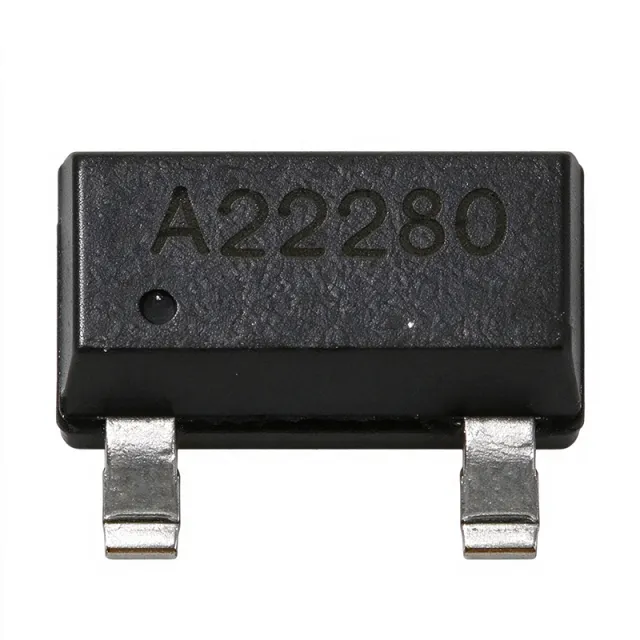
CDSOT23-SM712 - 7V/12V Asym RS-485 TVS Array 400W | Bourns
N.º de pieza: CDSOT23-SM712 ✓ Activo| Cant. | Precio unitario | Total |
|---|---|---|
| 1 | $0.5062 | $0,51 |
| 10 | $0.3656 | $3,66 |
| 100 | $0.3234 | $32,34 |
| 500 | $0.3094 | $154,70 |
| 1.000 | $0.2953 | $295,30 |
CDSOT23-SM712 Descripción general
A TVS diode array is a specialized class of transient voltage suppressor that integrates multiple steering/clamps in one package to protect differential data ports. The CDSOT23-SM712 belongs to the diode array > TVS array > ESD protection IC > circuit protection hierarchy. These arrays are essential companions to bus transceivers (RS-485, CAN, Profibus), where the transceiver's own absolute-maximum ratings are routinely violated by ESD, EFT, or surge events on the bus cable.
Key features include IEC 61000-4-2 (ESD) protection to +/-30 kV air and +/-30 kV contact, IEC 61000-4-4 (EFT) to 40 A (5/50 ns), and IEC 61000-4-5 (surge) to 17 A (8/20 us). The device provides low capacitance (per datasheet typical application) to preserve signal integrity at high data rates, and the SOT-23-3 footprint is the industry-standard pinout for SM712-style arrays. A low leakage current at 5 V maximises battery life in quiescent-mode industrial nodes.
The CDSOT23-SM712 uses an asymmetric avalanche-breakdown architecture: the 7 V TVS clamps positive transients on each data line relative to ground, while the 12 V TVS clamps the larger negative excursions permitted by RS-485. This dual-window topology is more efficient than two identical TVS diodes, because a single 12 V symmetric array would clip legitimate -7 V bus signalling, while a 7 V symmetric array would not survive the -25 V cable discharge that the RS-485 standard tolerates. The Bourns design matches the SM712 reference footprint exactly, so engineers can swap between vendors (Bourns, ST, NXP, MSKSEMI, YINT) without PCB rework.
Typical applications include RS-485/RS-422 fieldbus nodes in industrial automation, Profibus and Modbus links, CAN bus nodes in heavy machinery and EV charging, HVAC controllers, building automation, smart-meter communication ports, and any line-driver exposed to ESD during cable mating or lightning-induced surge on long outdoor runs. The asymmetrical window is also useful for CAN-H and CAN-L protection where one rail must withstand -12 V cross-wiring faults.
When designing with this device, place the CDSOT23-SM712 within 10 mm of the bus connector and keep the ground return path short and wide. Do not rely on the TVS alone for surge survival above 17 A - upstream PTCs or PTC+fuse combinations may be required to meet IEC 61000-4-5 level 4. The SOT-23-3 pad pattern is identical to industry-standard SOT-23, allowing use of standard land pattern footprints.
This page synthesizes distributor pricing, drop-in alternatives, and practical PCB layout notes not found in the manufacturer datasheet alone - including a same-package alternative table engineers can use when second-sourcing for supply-chain resilience.
Alternativas directas para CDSOT23-SM712 — mismo encapsulado, compatible pin a pin. Se excluyen las piezas de otro encapsulado que requieren retrabajo de la PCB.
Herramienta de comparación rápida — seleccione piezas alternativas para compararlas lado a lado:
CDSOT23-SM712-MS
📋 Alternativa de referencia (no en el catálogo)
ESDSM712
📋 Alternativa de referencia (no en el catálogo)
SM712
📋 Alternativa de referencia (no en el catálogo)
PSM712
📋 Alternativa de referencia (no en el catálogo)
CDSOT23-SM712 Especificaciones
| Manufacturer | Bourns Inc. |
| Series | CDSOT23-SM712 |
| Device Type | TVS Diode Array (asymmetrical) |
| Encapsulado | SOT-23-3 |
| Tipo de montaje | Surface Mount |
| Peak Pulse Power (8/20 us) | 400 W |
| Working Peak Reverse Voltage (Side 1) | 7 V |
| Working Peak Reverse Voltage (Side 2) | 12 V |
| Minimum Breakdown Voltage (Side 1) | 7.5 V |
| Minimum Breakdown Voltage (Side 2) | 13.3 V |
| Maximum Clamping Voltage at 17 A (8/20 us) | 14 V (positive) / 26 V (negative) |
| Peak Pulse Current (8/20 us) | 17 A |
| ESD Protection (IEC 61000-4-2) | +/-30 kV air, +/-30 kV contact |
| EFT Protection (IEC 61000-4-4) | 40 A (5/50 ns) |
| Surge Protection (IEC 61000-4-5) | 17 A (8/20 us) |
| Number of Channels | 2 (asymmetrical pair) |
| Polarity | Bidirectional (asymmetrical) |
| Estado RoHS | Compliant |
Configuración de pines de CDSOT23-SM712
| Pin 1 | Line 1 — Protected data line 1 (positive-polarity TVS clamp to GND) |
| Pin 2 | Line 2 — Protected data line 2 (negative-polarity TVS clamp to GND) |
| Pin 3 | GND — Ground reference for both TVS clamps - connect to chassis/earth ground via short, wide trace |
Aplicaciones típicas
CDSOT23-SM712 es adecuado para 6 aplicacións: RS-485/RS-422 Fieldbus Protection, CAN Bus Node Protection, Profibus and Modbus Field Nodes, Building Automation and HVAC, Smart Meter Communication Ports, Industrial Sensor and Encoder Links.
RS-485/RS-422 Fieldbus Protection
The CDSOT23-SM712's asymmetric 7 V/12 V window directly tracks the TIA/EIA-485 common-mode specification, making it the default TVS for industrial RS-485 transceivers such as the MAX3485, SN65HVD75, and ADM485. Place the device within 10 mm of the bus connector so that the 26 V clamping at 17 A (8/20 us) keeps the transceiver absolute-maximum ratings intact during cable discharge events. Unlike a 5 V TVS, the 7 V positive threshold does not clip legitimate +5 V differential signalling, while the 12 V negative threshold survives -25 V cross-wiring faults common in factory installations.
Recomendado
CAN Bus Node Protection
CAN bus nodes in automotive and industrial systems must survive -12 V cross-wiring faults and high-voltage jump-start transients. The CDSOT23-SM712's 12 V negative rail accommodates this asymmetry, while the 7 V positive rail protects against 24 V jump-start surges clamped to safe levels. With IEC 61000-4-2 +/-30 kV ESD and IEC 61000-4-5 17 A surge ratings, the array delivers CE-marked EMC compliance for CAN nodes on construction equipment, EVs, and heavy machinery. Place one CDSOT23-SM712 across CAN-H and CAN-L with both lines tied to pins 1 and 2 and ground to pin 3.
Recomendado
Profibus and Modbus Field Nodes
Profibus DP and Modbus RTU nodes operate over long, unshielded cable runs in industrial plants where induced surges from motors and switching contactors are routine. The CDSOT23-SM712's 400 W peak pulse rating and IEC 61000-4-5 17 A surge capability protect Profibus drivers like the LTC2875 and Modbus transceivers from field-induced transients. The asymmetric window is essential because Profibus drivers swing -7 V to +12 V in their common-mode range; symmetric 5 V arrays would clip legitimate signals. The SOT-23-3 footprint is industry-standard for Profibus protection ICs.
Recomendado
Building Automation and HVAC
Building automation controllers (BACnet, LonWorks, Modbus over RS-485) are installed near HVAC equipment with high inductive switching transients. The CDSOT23-SM712's +/-30 kV IEC 61000-4-2 ESD rating handles installer-touch discharge during commissioning, while the 17 A surge rating survives contractor-induced voltage spikes. The asymmetric window tracks BACnet's -7 V to +12 V common-mode range, and the small SOT-23-3 footprint fits inside the compact thermostat and damper-actuator enclosures typical of modern building automation hardware.
Recomendado
Smart Meter Communication Ports
Smart electricity, water, and gas meters expose their RS-485 or M-Bus communication ports to outdoor surges during storms and grid switching events. The CDSOT23-SM712 provides IEC 61000-4-5 17 A surge capability in a SOT-23-3 footprint small enough to fit inside the meter enclosure alongside the isolated transceiver. The 7 V/12 V asymmetric window accommodates meter-side ground potential rise, while the low capacitance preserves M-Bus and RS-485 signal integrity at typical 9600-115200 baud rates used in AMI networks.
Recomendado
Industrial Sensor and Encoder Links
Industrial encoders, scales, and absolute-position sensors transmit over RS-422/RS-485 from rotating machinery with high EMI. The CDSOT23-SM712 protects the receiver inputs of encoders using the AM26LV31/AM26LV32 RS-422 driver/receiver pair from encoder-cable ESD and common-mode transients. The 17 A surge rating handles 24 V industrial supply cross-wiring, and the asymmetric window tolerates the +/-10 V common-mode range of the AM26LV32 without clipping signals or false-triggering on noise. The SOT-23-3 footprint allows placement directly at the encoder cable gland.
Recomendado
Resumen de productos recomendados
Datos de referencia de ingeniería para CDSOT23-SM712 — comparación, orientación de diseño e información de cumplimiento.
Guía de selección
Comparación con alternativas
| Parámetro | Este producto | CDSOT23-SM712-MS | ESDSM712 | SM712 | PSM712 | CDSOT23-SM712 |
|---|---|---|---|---|---|---|
| Brand | Bourns | MSKSEMI | YINT | STMicroelectronics | Protek Devices | GOODWORK |
| Package | SOT-23-3 | SOT-23-3 - same | SOT-23-3 - same | SOT-23-3 - same | SOT-23-3 - same | SOT-23-3 - same |
| Working Voltage (Vrwm) Side 1 | 7 V | 7 V | 7 V | 7 V | 7 V | 7 V |
| Working Voltage (Vrwm) Side 2 | 12 V | 12 V | 12 V | 12 V | 12 V | 12 V |
Diferenciadores clave
- Asymmetric 7 V/12 V window matched to RS-485 common-mode range (frente a PSM712)
- Industry-default SM712 footprint with second-source pinout (frente a SM712 (STMicroelectronics))
- IEC 61000-4-2 +/-30 kV air/contact ESD rating (frente a ESDA6V1SC5)
Notas de diseño
Place the CDSOT23-SM712 within 10 mm of the protected bus connector so that trace inductance between the connector and TVS is minimized. The ground pin (pin 3) must connect to a low-impedance ground via - one via only, placed within 1 mm of the pad. Estimated: a 5 mm trace of 0.2 mm width has roughly 5 nH of inductance; at 17 A (8/20 us) with di/dt of 1.3 A/ns, that inductance would induce 6.5 V of overshoot, defeating the 26 V clamping spec. Use a ground pour directly under the device and stitch with multiple vias to chassis ground.
Do not substitute a symmetric 5 V or 12 V TVS array for the asymmetric CDSOT23-SM712 on RS-485 ports. A 5 V symmetric array will clip legitimate -7 V bus signalling and cause data corruption; a 12 V symmetric array will not survive an ESD strike below 12 V on the positive rail. The asymmetric window is the defining engineering feature, not a marketing distinction. Also note: the SM712 family is asymmetric - do not confuse with SM712J (single 5 V protection) used in signal-level ESD clamping.
Route the protected and unprotected sides of the bus through the CDSOT23-SM712 with no stubs - place the TVS in-line with the data path. Use a 4-layer stackup with a solid ground plane on layer 2 directly under the TVS; this provides the lowest ground-return inductance. Estimated: a 4-layer FR4 board with 0.2 mm prepreg to the ground plane has roughly 0.5 nH per via pair - acceptable for 17 A surge but not for 30 A. If your surge requirement exceeds 17 A, stack two CDSOT23-SM712 devices in parallel on adjacent ground vias.
The CDSOT23-SM712's capacitance (per datasheet typical value) is low enough not to distort RS-485 signals at 10 Mbps, but at higher data rates (50 Mbps) verify eye-diagram closure with the actual layout. For very high-speed links (above 100 Mbps), consider a lower-capacitance alternative such as a dedicated signal-line ESD array, or place a series ferrite bead between the TVS and the protected IC to isolate the capacitive load.
Información de cumplimiento
RoHS and REACH compliant per Bourns product page. Not AEC-Q100 qualified; for automotive CAN bus, consider an AEC-Q100 qualified alternative such as NXP's PESD1CAN or ON Semi NUP2105L. Halogen-free per Bourns datasheet.
