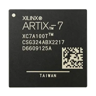
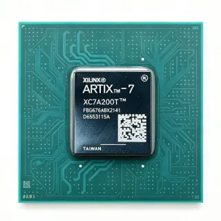
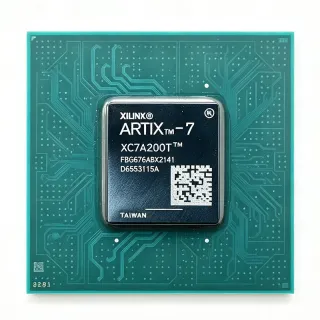
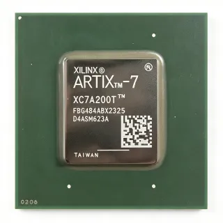
LFE2-20E-5F256I - 21K LUT ECP2 FPGA, 193 I/O, 256-FPBGA | Lattice
N.º de pieza: LFE2-20E-5F256I ✓ ActivoLFE2-20E-5F256I Descripción general
An FPGA (field programmable gate array) is a reconfigurable digital integrated circuit whose logic, interconnect and I/O are defined by a bitstream loaded from a configuration memory rather than by a fixed mask. In the product hierarchy an FPGA sits above programmable logic, sits alongside CPLD devices, and belongs to the broader class of programmable logic semiconductors used to shorten development cycles in control, interface and signal-processing designs.
Key features of this device include 2,625 configurable logic blocks (LABs), a 193-pin user I/O complement for high external connectivity, and 276 Kb of EBR block RAM for on-chip buffering, dual-port FIFO storage and video line buffers. The -5 speed grade and industrial temperature rating of -40 °C to +100 °C junction temperature suit continuous industrial duty, while the 1.2 V core supply keeps power dissipation manageable in densely packed systems.
Architecturally, the ECP2 family uses a LUT4-based logic fabric with a programmable interconnect switch matrix, distributed registers, block RAM and dedicated DSP multipliers, allowing medium-complexity designs such as bus bridges, protocol controllers and multi-channel acquisition front ends to be implemented in a single device. A single 1.2 V core rail simplifies power sequencing compared with split-rail devices.
Typical applications include industrial factory automation controllers, industrial Ethernet and fieldbus protocol bridges, camera and image sensor interface pipelines, LED and video timing generators, and data acquisition front ends that need deterministic parallel I/O with on-chip buffering.
A key design consideration is I/O assignment: with 193 user I/O in a 256-ball FBGA, pin mapping is constrained by the package, so plan bank assignments and voltage standards against the package drawing before committing the board layout. Decoupling and configuration-memory readiness should also be verified against the manufacturer power-up sequencing guidance.
Alternativas directas para LFE2-20E-5F256I — mismo encapsulado, compatible pin a pin. Se excluyen las piezas de otro encapsulado que requieren retrabajo de la PCB.
Variantes de esta serie
Modelos de la misma serie compatibles directamente con LFE2-20E-5F256I (mismo factor de forma y huella) — difiere en Device Type, Package, User I/O.
LFE2-20E-5FN256I
✅ Sustitución directa📋 Alternativa de referencia (no en el catálogo)
LFE2-20E-5FN256C
✅ Sustitución directa📋 Alternativa de referencia (no en el catálogo)
LFE2M20SE-5F256I
✅ Sustitución directa📋 Alternativa de referencia (no en el catálogo)
LFE2-20E-6FN256C
✅ Sustitución directa📋 Alternativa de referencia (no en el catálogo)
LFE2-20E-5F256C
✅ Sustitución directa ⚠️ Especificaciones sin verificarConsulte el precio
Ver hoja de datos →LFE2-25E-5F256I
✅ Sustitución directa ⚠️ Especificaciones sin verificar📋 Alternativa de referencia (no en el catálogo)
LFE2-20E-5F256I Valores máximos y características eléctricas
| Device Type | ECP2 field programmable gate array (FPGA) |
| Logic Elements | 21,000 |
| LUTs | 21K |
| Configurable Logic Blocks (LABs / CLBs) | 2,625 |
| User I/O | 193 |
| Embedded Block RAM (EBR) | 282,624 bits (276 Kb) |
| Core Supply Voltage | 1.2 V |
| Maximum Frequency | 311 MHz |
| Speed Grade | -5 |
| Rango de temperatura de funcionamiento | -40 °C to +100 °C (junction, industrial) |
| Encapsulado | 256-FPBGA, 17 x 17 mm |
| Tipo de montaje | Surface Mount |
| Lead-Free Status | Lead free |
| Series | Lattice ECP2 / ECP2M |
Guía de configuración de pines de LFE2-20E-5F256I 256-fpbga, 17 x 17 mm
Configuración de pines para LFE2-20E-5F256I (encapsulado 256-fpbga, 17 x 17 mm). Este CI digital incluye GPIO, interfaces de comunicación (UART, SPI, I2C) y pines de alimentación. Consulte la hoja de datos del fabricante para conocer las funciones alternativas de los pines y las opciones de configuración. Esencial para el diseño de sistemas embebidos y el diseño de PCB.

No hay datos detallados de patillaje disponibles para LFE2-20E-5F256I.
Consulte la hoja de datos para ver la configuración completa de patillas.
Aplicaciones típicas
LFE2-20E-5F256I es adecuado para 6 aplicacións: Industrial Factory Automation Controller, Industrial Ethernet and Fieldbus Protocol Bridge, Camera and Image Sensor Interface Pipeline, LED Lighting and Display Timing Control, Data Acquisition and Signal Conditioning Front End, Automotive and Heavy Vehicle Telemetry Control.
Industrial Factory Automation Controller
The LFE2-20E-5F256I fits machine controllers that must combine a lot of discrete fieldbus and sensor connections with deterministic logic. Its 193 user I/O in a 256-FPBGA package lets one device absorb encoder inputs, limit-switch sensing and actuator drive-enable signalling that would otherwise need several CPLDs, while 21,000 logic elements and 2,625 LABs can host a complete state machine plus protocol engine. The industrial -40 °C to +100 °C junction rating is appropriate for cabinet-mounted equipment near motors and heated zones, and the 276 Kb of embedded block RAM provides FIFOs and packet buffers for cyclic fieldbus traffic. The 1.2 V core rail and 311 MHz -5 grade clocking give comfortable timing margin for 1 ms-class control loops.
Recomendado
Industrial Ethernet and Fieldbus Protocol Bridge
Converting between industrial protocols such as Modbus, EtherCAT sub-device handling or proprietary serial links requires a device with wide parallel capture ability and enough on-chip memory to absorb frame bursts. The LFE2-20E-5F256I delivers 193 user I/O for parallel bus capture, 276 Kb of EBR for receive FIFOs and packet assembly, and 21K LUTs for CRC generation, byte stuffing and state management. Because ECP2 devices support configuration from standard serial flash, a bridge can be updated in the field without rework. The -5 speed grade at 311 MHz supports deterministic latency handling, and the industrial temperature class covers both machine-side and outdoor cabinet installations.
Recomendado
Camera and Image Sensor Interface Pipeline
Image sensor front ends need wide parallel data capture, precise clocking and local line buffering, which the LFE2-20E-5F256I provides through 193 user I/O, 276 Kb of embedded block RAM and a 1.2 V core. A Bayer or parallel CMOS sensor stream can be captured into EBR line buffers, de-noised and re-packed into a simpler parallel or serial interface for downstream processing. The 311 MHz -5 grade clocking supports pixel clocking and parallel-to-serial conversion at line rates, while the 256-FPBGA land pattern keeps the routing between sensor connector and FPGA short. The industrial temperature rating suits camera housings and outdoor surveillance installations that are not climate controlled.
Recomendado
LED Lighting and Display Timing Control
LED drivers, video timing generators and multi-panel display controllers need many repetitive timing channels plus a control engine, a profile that maps well onto the LFE2-20E-5F256I. The 21K LUT fabric can implement multiple PWM channels, gamma correction and blanking logic, and 193 user I/O drives panel data lines, sync outputs and driver chip-selects directly. The 276 Kb of EBR can hold lookup tables and frame buffers for small displays without external memory. With the -5 speed grade reaching 311 MHz, timing generation for high refresh-rate panels is achievable, and the single 1.2 V core keeps the supply design simple for space-constrained display modules.
Recomendado
Data Acquisition and Signal Conditioning Front End
Multi-channel acquisition systems combine parallel ADC data capture with gain control, triggering and data formatting, which is exactly the workload the LFE2-20E-5F256I is built for. Its 193 user I/O allows several ADCs to be sampled in parallel, 276 Kb of EBR holds acquisition buffers and trigger windows, and 21K LUTs provide digital filtering, decimation and packetization logic. The 311 MHz -5 grade internal clock gives deterministic sample timing for trigger-based capture, and the industrial temperature range allows placement near the analog front end in unconditioned racks. Block RAM can also be reconfigured as dual-port FIFO for streaming directly into a host processor or a fast serial link.
Recomendado
Automotive and Heavy Vehicle Telemetry Control
Body and vehicle telemetry modules need a mix of CAN or LIN interfaces, discrete I/O and a small control processor, with a temperature range suitable for harsh vehicle environments. The LFE2-20E-5F256I provides 193 user I/O for sensor aggregation and discrete control lines, 21K LUTs for protocol stack implementation, and 276 Kb of EBR for message buffering and diagnostic logging. The -40 °C to +100 °C junction rating covers vehicle interior and sheltered exterior positions, and the single 1.2 V core simplifies the power tree next to a 12 V or 24 V bus. Serial-flash configuration also allows firmware-like bitstream updates during service.
Recomendado
Resumen de productos recomendados
Datos de referencia de ingeniería para LFE2-20E-5F256I — comparación, orientación de diseño e información de cumplimiento.
Guía de selección
Comparación con alternativas
| Parámetro | Este producto | LFE2-20E-5FN256I | LFE2-20E-5FN256C | LFE2M20SE-5F256I | LFE2-20E-6FN256C | LFE2-20E-5F256C |
|---|---|---|---|---|---|---|
| Package | 256-FPBGA (17 x 17 mm) | 256-FPBGA (17 x 17 mm) - same | 256-FPBGA (17 x 17 mm) - same | 256-FPBGA (17 x 17 mm) - same | 256-FPBGA (17 x 17 mm) - same | 256-FPBGA (17 x 17 mm) - same |
| Brand | Lattice Semiconductor | Lattice Semiconductor | Lattice Semiconductor | Lattice Semiconductor | Lattice Semiconductor | Lattice Semiconductor |
| Logic Elements / LUTs | 21,000 (21K LUTs) | 21,000 | 21,000 | 21,000 | 21,000 | 21,000 |
| User I/O | 193 | 193 | 193 | 193 | 193 | 193 |
| Speed Grade | -5 | -5 | -5 | -5 | -6 (faster grade) | -5 |
| Temperature Range | -40 °C to +100 °C (junction, industrial) | -40 °C to +100 °C (industrial) | Commercial grade | -40 °C to +100 °C (industrial) | Commercial grade | Commercial grade |
| Core Supply Voltage | 1.2 V | 1.2 V | 1.2 V | 1.2 V | 1.2 V | 1.2 V |
| Special Features | ECP2 standard device, no multiplier array | ECP2 standard device | ECP2 standard device | ECP2M with DSP multiplier resources | Faster -6 grade, ECP2 standard device | ECP2 standard device |
Diferenciadores clave
- Combines a 21K LUT fabric with the highest I/O count in the ECP2 20K class (frente a LFE2-12E-5F484I)
- Industrial temperature coverage as standard with the -5 speed grade (frente a LFE2-20E-5F256C)
- Timing headroom is lower at the -5 grade, giving a clearer upgrade path (frente a LFE2-20E-6FN256C)
- No multiplier array, so fixed-point DSP work maps onto EBR and LUTs instead (frente a LFE2M20SE-5F256I)
Notas de diseño
The LFE2-20E-5F256I runs from a single 1.2 V core rail, but dynamic current swings sharply with logic and block RAM utilisation. Estimated: at 311 MHz with roughly 30 percent logic utilisation and 50 percent EBR toggling, use the manufacturer power estimator with your own utilisation and activity factors rather than a nominal number, and size the core regulator for the worst-case dynamic corner at the -5 grade. Place the bulk capacitor plus a 0.1 uF high-frequency capacitor directly on the 1.2 V and ground balls, and keep the supply loop area under the package as small as possible.
With 193 user I/O in a 256-ball, 17 x 17 mm FBGA, ball-escape and break-out routing dominate layout effort. Assign signals to banks so that each bank carries a single I/O voltage standard, and reserve the configuration pins (CONFIG, DONE, INIT) on convenient ball positions near the serial flash and pull-up network. Differential pairs must be routed length-matched on the inner layers, and every ball used by a high-speed interface should be assigned before the pinout is frozen; review the package drawing in the manufacturer datasheet for the authoritative ball map.
A common error is treating the -5 and -6 speed grades as interchangeable on a timing-critical design: the -5 grade has less timing margin at the same clock, so a design that closes on LFE2-20E-6FN256C may fail on the LFE2-20E-5F256I. Another frequent mistake is swapping the industrial I-grade for a commercial C-grade part; the pinout is unchanged but the junction limit falls from 100 °C to 70 °C, which is unacceptable in heated cabinets, vehicle interiors and outdoor enclosures. Verify grade and temperature class in the ordering information before releasing a build.
For parallel sensor or bus capture at the -5 grade, treat the 311 MHz internal clock as the reference point for external timing, and add series termination on high-speed outputs where the board traces exceed a few centimetres. Keep the EBR-based buffers adjacent to the device so that line lengths to memory stay short and skew-controlled, and use the I/O standard of each bank consistently; mixing standards within one bank is a frequent cause of timing closure failures in ECP2 designs.
Información de cumplimiento
The part listing describes the LFE2-20E-5F256I as lead free in a 17 x 17 mm PBGA-256 package. RoHS, REACH, halogen-free and conflict-minerals status are not stated on the product pages and are therefore reported as unknown; the industrial temperature option is a commercial grade rather than an AEC-Q100 qualified automotive device.