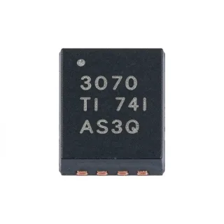
LM2903VQPWRG4Q1 - 30V Dual Comparator | Texas Instruments
N.º de pieza: LM2903VQPWRG4Q1 ✓ ActivoLM2903VQPWRG4Q1 Descripción general
A comparator is an analog integrated circuit that compares two input voltages and changes its output state when the non-inverting input rises above the inverting input. The differential comparator belongs to the broader comparator, analog IC, and semiconductor hierarchies. It is commonly used for threshold detection, overvoltage and undervoltage monitoring, sensor conditioning, and converting analog levels into digital logic signals.
The device provides lower offset voltage, higher supply-voltage capability, lower supply current, lower input bias current, lower propagation delay, and improved 2 kV ESD performance than earlier LMx93-family devices. Typical input offset voltage is no more than 7 mV at 25°C, supply current is 0.4 mA per comparator, and nominal response time is 1.3 microseconds. Its open-collector outputs allow wired logic, pull-up resistors, and level translation to the supply voltage used by the receiving logic.
Each channel has independent noninverting and inverting inputs, so the two comparators can monitor separate signals or implement two thresholds. The common-emitter open-collector output sinks current from an external pull-up and naturally goes to a high-impedance state when the comparator is inactive. Because the output stage is not push-pull, output rise time depends on the pull-up resistor, total bus capacitance, and leakage current rather than only on internal drive strength.
Typical uses include automotive battery monitoring, sensor threshold detection, industrial control inputs, overvoltage and undervoltage protection, and signal conditioning between analog sensors and digital controllers. Single-supply operation simplifies power architecture, while dual-supply operation allows inputs and output pull-ups to reference different voltage domains. The wide 30 V supply range also accommodates 12 V and 24 V automotive electrical environments when the absolute maximum ratings and transient requirements are respected.
For PCB design, keep the comparator inputs and power-ground return paths compact, connect the exposed-decoupling route to a low-impedance ground plane, and place the output pull-up resistor near the driven logic input. Avoid routing sensitive input traces beside power outputs or long pull-up traces. Input protection may be required in external automotive connectors, and production designs should validate the complete system for conducted noise, ESD events, supply transients, and open-collector pull-up compatibility.
This page combines exact ordering information, automotive qualification details, drop-in comparator choices, application-specific engineering guidance, and a parameter comparison to help engineers select and implement the LM2903VQPWRG4Q1 correctly.
Alternativas directas para LM2903VQPWRG4Q1 — mismo encapsulado, compatible pin a pin. Se excluyen las piezas de otro encapsulado que requieren retrabajo de la PCB.
LM2903VQPWRQ1
✅ Sustitución directaConsulte el precio
Ver hoja de datos →LM2903QPWRQ1
✅ Sustitución directaConsulte el precio
Ver hoja de datos →LM2903VQPWR
✅ Sustitución directa📋 Alternativa de referencia (no en el catálogo)
LM2903PWRG4
✅ Sustitución directaConsulte el precio
Ver hoja de datos →LM2903BVPWRQ1
✅ Sustitución directa ⚠️ Especificaciones sin verificar📋 Alternativa de referencia (no en el catálogo)
LM2903VQPWRG4Q1 Valores máximos y características eléctricas
| Comparator Type | Dual differential comparator |
| Number of Channels | 2 channels |
| Channel Independence | 2 independent comparators |
| Tipo de salida | Open-collector |
| Supply Voltage Maximum | 30 V |
| Supply Voltage Minimum | 2 V |
| Dual-Supply Total Voltage Range | 2 V to 36 V |
| Supply Current per Comparator | 0.4 mA typical |
| Input Offset Voltage at 25°C | 7 mV maximum |
| Nominal Response Time | 1.3 us |
| Enhanced ESD Performance | 2 kV |
| Automotive Qualification | AEC-Q100 Grade 0 and Grade 1 |
| Rango de temperatura de funcionamiento | -40°C to +150°C |
| Encapsulado | 8-pin TSSOP |
| Package Length | 3 mm |
| Tipo de montaje | Surface mount |
| Supply Configuration | Single supply or dual supplies |
| Input Common-Mode Range | Rail-to-rail |
Guía de configuración de pines de LM2903VQPWRG4Q1 3 mm
Configuración de pines para LM2903VQPWRG4Q1 (encapsulado 3 mm). Este componente analógico presenta pines de entrada, salida y alimentación. Consulte la hoja de datos del fabricante para conocer las configuraciones de los pines de ajuste de offset, compensación y habilitación. Ideal para circuitos de acondicionamiento de señal y amplificadores.

No hay datos detallados de patillaje disponibles para LM2903VQPWRG4Q1.
Consulte la hoja de datos para ver la configuración completa de patillas.
Aplicaciones típicas
LM2903VQPWRG4Q1 es adecuado para 6 aplicacións: Automotive Battery Threshold Detection, Overvoltage and Undervoltage Protection, Industrial Sensor Interfacing, Automotive Actuator Discrete Control, Windowed Logic and Signal Qualification, Analog-to-Digital Boundary Detection.
Automotive Battery Threshold Detection
The LM2903VQPWRG4Q1 suits 12 V and 24 V automotive systems that must detect an abnormal battery or charging voltage. Its 30 V maximum supply and AEC-Q100 Grade 0 or Grade 1 identification fit many low-voltage monitoring architectures, while the 0.4 mA typical supply current per comparator limits continuous overhead. Two independent channels can monitor separate thresholds. Connect an open-collector output to a pull-up and MCU input, and validate the complete design for load dump, reverse battery, ESD, and transient conditions before production use.
Recomendado
Overvoltage and Undervoltage Protection
Use the two independent comparator channels to implement separate overvoltage and undervoltage protection thresholds. The LM2903VQPWRG4Q1 offers a 7 mV maximum input offset at 25°C and a nominal 1.3 us response time, allowing compact threshold decisions without a more complex mixed-signal controller. Its open-collector outputs can pull down discrete control lines or digital inputs through external pull-ups. Account for input offset, resistor tolerance, propagation delay, and automotive transient protection when setting the trip points.
Recomendado
Industrial Sensor Interfacing
The LM2903VQPWRG4Q1 can compare a sensor-derived voltage with a reference or threshold and provide a logic-compatible open-collector event signal. Its 2 V to 30 V supply range supports industrial systems with regulated intermediate rails, and the 0.4 mA typical current per channel is useful for distributed sensing. Add input filtering, reference conditioning, and protection as required. The external pull-up determines the output logic level, allowing the same comparator to drive several controller families without changing the PCB footprint.
Recomendado
Automotive Actuator Discrete Control
The LM2903VQPWRG4Q1 can form the decision stage of a discrete low-side actuator driver by comparing a command or feedback voltage and pulling a control node low through its open-collector output. Its two channels allow independent handling of two control functions, and the 30 V supply capability is relevant to 12 V and 24 V vehicle systems. Keep the comparator supply separate from inductive loads where practical, use a suitable pull-up rail, and include flyback protection for relays, solenoids, and motors to prevent switching transients from reaching the comparator inputs.
Recomendado
Windowed Logic and Signal Qualification
Two LM2903VQPWRG4Q1 channels can monitor the lower and upper limits of an analog signal and combine the results into a valid-window indication. The nominal 1.3 us response time is suitable for many control and qualification signals, while 0.4 mA typical supply current per comparator supports low-power designs. Because the outputs are open collector, pull-ups and external logic determine the final system behavior. Check the datasheet for input common-mode limits and include hysteresis or filtering when noise near either threshold could cause repeated transitions.
Recomendado
Analog-to-Digital Boundary Detection
The LM2903VQPWRG4Q1 can supervise an analog node before it enters an ADC input and assert an open-collector warning when the signal crosses a defined threshold. This is useful for rail, sensor, or signal-range supervision where the controller needs a hardware fault indication in addition to numeric ADC readings. The 7 mV maximum offset at 25°C and 1.3 us nominal response time support straightforward thresholding, but system accuracy also depends on the reference, divider tolerances, ADC noise, and any deliberate hysteresis around the switching point.
Recomendado
Resumen de productos recomendados
Datos de referencia de ingeniería para LM2903VQPWRG4Q1 — comparación, orientación de diseño e información de cumplimiento.
Guía de selección
Comparación con alternativas
| Parámetro | Este producto | LM2903VQPWRQ1 | LM2903QPWRQ1 | LM2903VQPWR | LM2903PWRG4 | LM2903BVPWRQ1 |
|---|---|---|---|---|---|---|
| Brand | Texas Instruments | Texas Instruments | Texas Instruments | Texas Instruments | Texas Instruments | Texas Instruments |
| Package | TSSOP-8 | TSSOP-8 - same package | TSSOP-8 - same package | TSSOP-8 - same package | TSSOP-8 - same package | TSSOP-8 - same package |
| Comparator Channels | 2 | 2 | 2 | 2 | 2 | 2 |
| Output Type | Open-collector | Open-collector | Open-collector | Open-collector | Open-collector | Open-collector |
| Automotive Qualification | AEC-Q100 Grade 0 and Grade 1 | AEC-Q100 Grade 0 and Grade 1 | AEC-Q100 Grade 0 and Grade 1 | Not stated for the standard ordering code | Automotive ordering family | AEC-Q100 Grade 0 and Grade 1 |
Diferenciadores clave
- Automotive qualification for extreme-temperature vehicle environments (frente a LM2903VQPWR)
- High-voltage V-grade supply capability (frente a LM2903PWRG4)
- Two independent channels with low supply consumption (frente a LM2903NG)
- Enhanced ESD performance in a compact TSSOP footprint (frente a LM2903QPWRQ1)
Notas de diseño
Assign comparator inputs and their reference signals on compact, quiet PCB traces, and route each channel directly to the relevant sensing network. Keep open-collector outputs and external pull-ups away from sensitive input traces where practical. Connect the device ground to the quiet signal-reference path rather than routing return current through a switching-power region. This separation reduces offset errors and prevents the 1.3 us response time from becoming a useful signal in the presence of switching-node coupling.
Do not treat the open-collector output as a push-pull logic output. Each output requires an external pull-up resistor and remains high-impedance while the comparator is inactive. Select the pull-up to establish the required logic-high voltage and rise time while limiting resistor dissipation and leakage sensitivity. In automotive wiring environments, protect the input pins and supply rail against ESD, reverse battery, load dump, and other transients; the 30 V supply rating is not a substitute for a complete protection network.
Place the device's supply bypass capacitor immediately across the supply and ground pins, using the capacitance and placement recommended by the manufacturer datasheet. Provide a low-impedance path from the capacitor to the ground plane, and avoid sharing a narrow neck with high-current return paths. Although typical supply current is 0.4 mA per comparator, switching nodes and external pull-up currents can still inject disturbances. Confirm the bypass network against the required EMC and automotive transient test conditions.
Add hysteresis or positive feedback when the compared signal can cross a threshold slowly or with noise. The 7 mV maximum offset at 25°C is only one contributor to switching accuracy; reference tolerance, input bias, resistor tolerances, and propagation delay also affect the decision point. For fast or noisy signals, use a Schmitt-trigger function or filtering, and keep the pull-up capacitance low enough to prevent excessive output rise time. Verify both threshold crossing delay and output overshoot on the assembled board.
Información de cumplimiento
Texas Instruments identifies the LM2903-Q1 family as AEC-Q100 Grade 0 and Grade 1 qualified and describes improved 2 kV ESD performance. RoHS, REACH, lead-free, halogen-free, and conflict-minerals status are not stated in the available product information.