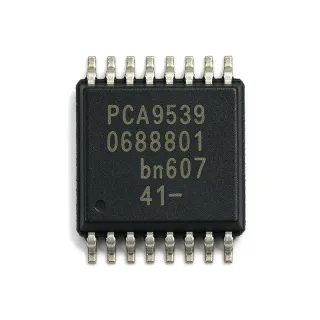
PCA9538APWJ - 8-Bit I/O Expander, 400 kHz | NXP
N.º de pieza: PCA9538APWJ ✓ ActivoPCA9538APWJ Descripción general
An I/O expander is an interface IC that extends the number of general-purpose digital inputs and outputs available to a host processor. The I2C interface connects the expander to SCL and SDA, while the eight port pins can operate as inputs or outputs. In the broader semiconductor hierarchy, the PCA9538APWJ is an I/O expander within interface ICs, a peripheral semiconductor, and a serial bus interface device.
Principal features include eight I/O ports, I2C and SMBus compatibility, a maximum 400 kHz bus rate, an interrupt output, and an active-low reset input. The interrupt mechanism lets a host detect a change on an input port without continuously polling all eight pins. Reset provides a defined startup state for the port configuration registers and supports deterministic system initialization.
The PCA9538A architecture separates serial bus control from parallel port access. The host writes to the configuration and output registers to establish pin direction and output levels, while input data can be read from the corresponding input register. Address and configuration information are managed through the device control registers. This register-based organization allows multiple compatible peripherals to coexist on the same two-wire bus when their addresses differ.
Typical uses include remote switch and button inputs, LED or relay-control outputs, sensor-interface connections, and general-purpose digital I/O in embedded products. The interrupt and reset functions are particularly useful in battery-powered and industrial equipment, where event-driven host processing can reduce unnecessary bus activity. The 16-pin TSSOP package also supports compact control boards with conventional surface-mount assembly.
Designers should confirm the power rail, pull-up arrangement, address pins, and voltage tolerances before layout release. I2C pull-up resistors must support the bus capacitance and operating speed, while the interrupt and reset traces should remain away from noisy switching nodes. Confirm the pin configuration and electrical limits directly in the NXP datasheet before committing the PCB footprint.
This product overview consolidates the device function, interface characteristics, package details, replacement considerations, and practical PCB guidance into an engineering-focused reference for evaluating the PCA9538APWJ in embedded I/O designs.
Alternativas directas para PCA9538APWJ — mismo encapsulado, compatible pin a pin. Se excluyen las piezas de otro encapsulado que requieren retrabajo de la PCB.
Variantes de esta serie
Modelos de la misma serie compatibles directamente con PCA9538APWJ (mismo factor de forma y huella) — difiere en Number of I/O Ports.
PCA9574PW,118
✅ Sustitución directa📋 Alternativa de referencia (no en el catálogo)
PCA9538PW
✅ Sustitución directa✓ En stock
$0.5086 / unidad
Ver hoja de datos →TCA9534APWR
✅ Sustitución directa📋 Alternativa de referencia (no en el catálogo)
PCA9538APWJ Especificaciones
| Device Type | 8-bit general-purpose I/O expander |
| Number of I/O Ports | 8 ports |
| Interfaz | I2C-bus and SMBus |
| Maximum I2C Bus Frequency | 400 kHz |
| Supported Bus Frequency Range | 100 kHz to 400 kHz |
| Tensión de alimentación de funcionamiento | 2.3 V to 5.5 V |
| Maximum Supply Voltage | 5.5 V |
| Interrupt Function | Yes, 1 interrupt output |
| Reset Function | Yes, active-low reset input |
| Número de pines | 16 pins |
| Encapsulado | TSSOP-16 |
| Tipo de montaje | Surface mount |
| I/O Configuration | 8 independently configurable ports |
Guía de configuración de pines de PCA9538APWJ tssop-16
Configuración de pines para PCA9538APWJ (encapsulado tssop-16). La numeración de pines, las funciones y los diagramas de conexión se definen en la hoja de datos del fabricante. Consúltela para conocer el footprint exacto y las directrices de soldadura.
No hay datos detallados de patillaje disponibles para PCA9538APWJ.
Consulte la hoja de datos para ver la configuración completa de patillas.
Aplicaciones típicas
PCA9538APWJ es adecuado para 6 aplicacións: Remote Switch and Button Inputs, LED and Relay Control Outputs, Industrial Control and Automation, Battery-Powered Sensor Interfaces, Embedded System Peripheral Expansion, Connected Device and IoT Control.
Remote Switch and Button Inputs
The PCA9538APWJ is well suited to connecting switches, push buttons, selectors, and contact inputs beyond the available GPIO pins of a microcontroller. Its eight configurable ports reduce parallel wiring to the host, while SCL and SDA handle configuration and status transfer over the I2C-bus. Operating up to 400 kHz supports reliable communication with a 2.3 V to 5.5 V system. The interrupt output can notify the controller when an input changes, reducing continuous polling. Designers should verify logic thresholds, input leakage, debounce requirements, and pull-up values in the NXP datasheet before assigning each switch or sensor signal.
LED and Relay Control Outputs
Eight configurable outputs allow the PCA9538APWJ to control LEDs, status indicators, relay drivers, or other digital loads when the host lacks sufficient direct output pins. The I2C-bus interface keeps the control path compact and supports configuration of output states through the device registers. A reset input gives the hardware a defined initialization path, while the interrupt output can report relevant port activity. Because the expander is designed for low-voltage digital signaling, load drivers and protection components may still be required. Confirm output current limits, output timing, and voltage compatibility in the manufacturer datasheet before connecting loads.
Industrial Control and Automation
The PCA9538APWJ can extend a controller in industrial automation equipment that needs discrete inputs and outputs beyond the host processor's native pin count. Eight remotely placed I/O channels, serial operation up to 400 kHz, reset control, and interrupt reporting provide a compact interface between embedded logic and field wiring. The 16-pin TSSOP package supports compact control boards, and the 2.3 V to 5.5 V operating range accommodates common embedded supply levels. Industrial implementations should add appropriate isolation, surge protection, and grounding as required by the field environment rather than treating the I/O expander as a standalone protection device.
Battery-Powered Sensor Interfaces
The PCA9538APWJ is useful in battery-powered sensor nodes when the microcontroller must monitor several digital sensor signals or control low-power peripheral inputs through a shared serial bus. The eight-port architecture reduces the number of direct host pins and wiring connections, while the interrupt function enables event-driven processing instead of frequent status polling. The device supports a 2.3 V to 5.5 V operating range and an I2C-bus rate up to 400 kHz. Actual battery savings depend on the host's sleep strategy, sensor leakage, pull-up current, and how often the controller accesses the expander, so those values should be measured in the complete system.
Embedded System Peripheral Expansion
The PCA9538APWJ provides a practical way to add general-purpose I/O to microcontrollers, processors, and programmable controllers with limited pin availability. A host can configure each of the eight channels as an input or output, read port state over the I2C-bus, and use the interrupt line for change notification. This arrangement is useful for panel controls, alarm inputs, and miscellaneous status signals. Because the device is an interface IC rather than a microcontroller, it requires a suitable host and bus support in firmware. Firmware should include startup register writes, bus timeout handling, and a defined reset sequence for deterministic operation.
Connected Device and IoT Control
In IoT and connected-device products, the PCA9538APWJ can consolidate several discrete control points behind an I2C-bus while preserving access to eight local signals. The interrupt output supports responsive handling of user controls or remote events, and the reset function helps initialize the board after power-up. Operation across a 2.3 V to 5.5 V supply range supports mixed embedded platforms, while the TSSOP-16 package helps maintain compact layouts. When multiple expanders share the bus, verify address selection and total pull-up capacitance. Keep the serial traces short, route them away from switching nodes, and confirm signal levels with every device on the bus.
Datos de referencia de ingeniería para PCA9538APWJ — comparación, orientación de diseño e información de cumplimiento.
Guía de selección
Comparación con alternativas
| Parámetro | Este producto | PCA9574PW,118 | PCA9538PW | TCA9534APWR |
|---|---|---|---|---|
| Brand | NXP Semiconductors | NXP Semiconductors | Texas Instruments | Texas Instruments |
| Package | TSSOP-16 | TSSOP-16 | TSSOP-16 | TSSOP-16 |
| Device Type | 8-bit I/O expander | 8-bit I/O expander | 8-bit I/O expander | 8-bit I/O expander |
| Number of I/O Ports | 8 ports | 8 ports | 8 ports | 8 ports |
| Serial Interface | I2C-bus and SMBus | I2C-bus | I2C-bus and SMBus | I2C-bus |
| Pin Count | 16 pins | 16 pins | 16 pins | 16 pins |
Diferenciadores clave
- NXP-documented 8-bit expander with interrupt and reset (frente a TCA9534APWR)
- Same 16-pin TSSOP footprint with matching 8-port count (frente a PCA9538PW)
- 100 kHz to 400 kHz serial operation (frente a PCA9574PW,118)
Notas de diseño
Place the PCA9538APWJ close to the I2C controller and the devices that use its eight port lines. Keep SCL and SDA routes short and away from switching-node copper. Route the interrupt and reset signals as dedicated nets, and observe the pin-description table in the NXP datasheet before assigning tracks. The TSSOP-16 land pattern must match the selected ordering suffix.
Select I2C pull-up resistors from the total bus capacitance, target rise time, and 400 kHz operating rate rather than using a single value across every board. Account for pull-up current at the lowest supply voltage and for every device that can connect to the bus. Verify that the controller, expander, and peripheral devices use compatible logic levels to prevent excessive input voltage.
Do not assume that equal package and port count guarantee software compatibility. Before replacing the PCA9538APWJ, compare I2C address selection, configuration-register bit definitions, output behavior, reset polarity, interrupt polarity, and startup timing. Update firmware if register addresses or semantics differ, and validate the assembled board across minimum and maximum supply conditions.
Include every I2C pull-up and port load in the power budget for the 2.3 V to 5.5 V operating range. The interrupt and reset inputs must maintain valid logic levels during startup, power reduction, and system reset. Use pull resistors or suitable source arrangements where external circuitry could leave these control pins floating.
Información de cumplimiento
No definitive RoHS, REACH, AEC-Q100, lead-free, halogen-free, or conflict-minerals statement appears in the cited product information. Confirm current declarations with NXP for the exact PCA9538APWJ ordering code.