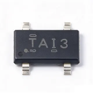
TL431AQDBZR - 2.495V Adjustable Shunt Reference | TI
N.º de pieza: TL431AQDBZR ✓ Activo| Cant. | Precio unitario | Total |
|---|---|---|
| 1 | $0.28 | $0,28 |
| 10 | $0.22 | $2,20 |
| 100 | $0.14 | $14,00 |
| 500 | $0.11 | $55,00 |
| 1.000 | $0.09 | $90,00 |
TL431AQDBZR Descripción general
A shunt voltage reference is a type of voltage reference IC that regulates voltage by shunting excess current to ground, operating in parallel with the load. Within the power management hierarchy (voltage reference -> shunt regulator -> power management IC), shunt references like the TL431 family are the workhorse feedback and error-amplification elements of isolated and non-isolated switch-mode power supplies. Because they need only a bias current to function, they can be configured from below 1V to 36V using two external resistors.
Key features include the wide adjustable output range of Vref to 36V, a sharp low dynamic output impedance, fast turn-on response, and low output noise. The 'A' grade guarantees +/-1% reference tolerance at 25C, while the 'Q' suffix denotes automotive qualification and operation across -40C to +125C, making the part suitable for under-hood and industrial environments where commercial-grade references drift out of spec.
Internally the TL431 combines a 2.495V bandgap reference with an operational amplifier and an output transistor; when the REF pin voltage exceeds the internal 2.495V threshold, the cathode conducts and sinks current. This makes it directly usable as the error amplifier in an optocoupler feedback loop of an AC-DC or DC-DC converter, replacing a discrete op-amp plus reference.
Typical applications include secondary-side feedback regulation in flyback and forward SMPS designs, adjustable linear regulator pass-element control, overvoltage protection crowbar circuits, and precision current-source/sink circuits.
Design consideration: ensure at least 1 mA continuous cathode bias current for guaranteed regulation accuracy, and keep the REF-pin trace short to minimize pickup in switching environments.
This page adds value beyond the datasheet by consolidating drop-in alternatives, application guidance, and cross-reference data into a single engineering-ready reference.
Alternativas directas para TL431AQDBZR — mismo encapsulado, compatible pin a pin. Se excluyen las piezas de otro encapsulado que requieren retrabajo de la PCB.
Variantes de esta serie
Modelos de la misma serie compatibles directamente con TL431AQDBZR (mismo factor de forma y huella) — difiere en Operating Temperature Range, Package, Adjustable Output Range, Reference Voltage (Vref), Minimum Cathode Current for Regulation.
Herramienta de comparación rápida — seleccione piezas alternativas para compararlas lado a lado:
TL431AQDBZRQ1
✅ Sustitución directa✓ En stock
$0.09 / unidad
Ver hoja de datos →TL431AIDBZR
✅ Sustitución directa✓ En stock
$0.08 / unidad
Ver hoja de datos →TL431BQDBZR
✅ Sustitución directa✓ En stock
$0.07 / unidad
Ver hoja de datos →TL431AQDBZT
✅ Sustitución directa ⚠️ Especificaciones sin verificar📋 Alternativa de referencia (no en el catálogo)
KA431AZ
✅ Sustitución directa📋 Alternativa de referencia (no en el catálogo)
AZ431AZ-ATRE1
✅ Sustitución directa📋 Alternativa de referencia (no en el catálogo)
TL431AQDBZR Valores máximos y características eléctricas
| Reference Type | Adjustable shunt voltage reference |
| Reference Voltage (Vref) | 2.495 V |
| Initial Accuracy | +/-1% at 25C |
| Adjustable Output Range | Vref (2.495 V) to 36 V |
| Maximum Cathode Current | 100 mA |
| Maximum Input Voltage (Cathode-Anode) | 36 V |
| Minimum Cathode Current for Regulation | 1 mA |
| Rango de temperatura de funcionamiento | -40C to +125C |
| Automotive Qualification | AEC-Q100 qualified (Q grade) |
| Encapsulado | SOT-23-3 (DBZ) |
| Tipo de montaje | Surface Mount |
| Estado RoHS | Compliant |
Configuración de pines de TL431AQDBZR
| Pin 1 | REF — Reference input, threshold at 2.495 V |
| Pin 2 | ANODE — Anode terminal, connect to ground |
| Pin 3 | CATHODE — Shunt output terminal, sinks up to 100 mA |
Aplicaciones típicas
TL431AQDBZR es adecuado para 6 aplicacións: Isolated Flyback SMPS Feedback, Adjustable Linear Regulator Control, Overvoltage Protection Crowbar, Precision Current Source and Sink, Automotive Module Local Reference, Battery Charger Voltage Regulation Loop.
Isolated Flyback SMPS Feedback
The TL431AQDBZR is the de-facto industry-standard error amplifier on the secondary side of isolated flyback and forward converters. Its 2.495V bandgap reference is tied to a resistor divider monitoring the output rail, and its shunt output sinks current through an optocoupler LED to modulate the PWM controller duty cycle on the primary side. The +/-1% initial accuracy of the A grade directly defines output voltage tolerance, while the -40C to +125C automotive rating suits industrial power supplies exposed to wide ambients. Designers should guarantee at least 1 mA cathode bias and compensate the loop with an RC network from CATHODE to REF, because the TL431 plus optocoupler pole dominates the loop crossover, typically around 1 kHz to 5 kHz.
Recomendado
Adjustable Linear Regulator Control
In discrete linear regulators, the TL431AQDBZR serves as both reference and error amplifier driving a PNP or N-channel pass element. The REF pin senses the output via a divider, and the cathode modulates pass-element base or gate drive, yielding regulation accuracy limited mainly by the +/-1% reference tolerance. Because the part handles the loop gain internally, the resulting regulator achieves far better line and load regulation than a Zener-based circuit. The automotive -40C to +125C range supports industrial 24V rail auxiliary supplies. Keep cathode current between 1 mA and roughly 20 mA to balance accuracy against package dissipation, and add a small compensation capacitor for stability with low-ESR output capacitors.
Recomendado
Overvoltage Protection Crowbar
The TL431AQDBZR makes a precise overvoltage detector: a divider scales the monitored rail to the 2.495V threshold, and when the rail exceeds the trip point, the cathode pulls low to drive a thyristor gate, SCR crowbar, or fuse-blowing transistor. The +/-1% accuracy gives a tightly controlled trip threshold compared to Zener-based detectors, whose tolerance is typically 5%. The automotive temperature rating ensures the trip point stays repeatable across -40C to +125C. Add a small hysteresis resistor from CATHODE to REF to prevent chattering near the threshold, and size divider resistors so REF bias current does not shift the trip point measurably.
Recomendado
Precision Current Source and Sink
By placing a sense resistor between ANODE and REF, the TL431AQDBZR enforces a fixed 2.495V across it, creating a precise shunt current sink of I = 2.495V / Rsense once the loop closes through an external transistor. This two-terminal-style constant current configuration achieves accuracy near the +/-1% reference tolerance, far better than a bare resistor fed from a supply rail. Applications include LED bias, sensor excitation, and battery charger trickle stages. The 100 mA cathode capability, with a pass device for larger currents, covers low-to-moderate current designs, and the automotive grade suits automotive sensor excitation across the full -40C to +125C ambient range.
Recomendado
Automotive Module Local Reference
In ECU and body-electronics modules, the AEC-Q100 qualified TL431AQDBZR provides a local precision threshold for undervoltage detection, sensor ratiometric correction, and ADC full-scale stretching. Because the Q grade carries automotive qualification and a -40C to +125C range, it can sit anywhere in the harness-adjacent environment without a separate qualification study. The 2.495V reference with +/-1% accuracy supports 12V rail window monitors when paired with a matched divider. Low dynamic output impedance keeps the reference quiet in switching-rich automotive EMC environments; place a 0.1 uF capacitor directly across CATHODE to ANODE and keep the REF node guarded from injected transients.
Recomendado
Battery Charger Voltage Regulation Loop
Charger circuits for lead-acid and lithium cells use the TL431AQDBZR as the precision setpoint element: the divider ratio sets the charge-termination voltage, and the shunt output modulates the series regulator or buck converter. The +/-1% A-grade accuracy matters because lithium charge voltage tolerance is typically +/-1% at the cell; combined with 0.1% divider resistors, the TL431AQDBZR keeps the full-loop tolerance tight without calibration. The 36V cathode rating allows direct connection in multi-cell stack supervision points. Ensure the minimum 1 mA cathode current is maintained at the lowest supply condition, and add temperature-compensated divider elements if charge voltage must track cell temperature coefficients.
Recomendado
Resumen de productos recomendados
Datos de referencia de ingeniería para TL431AQDBZR — comparación, orientación de diseño e información de cumplimiento.
Guía de selección
Comparación con alternativas
| Parámetro | Este producto | TL431AQDBZRQ1 | TL431AIDBZR | TL431BQDBZR | KA431AZ | AZ431AZ-ATRE1 |
|---|---|---|---|---|---|---|
| Package | SOT-23-3 (DBZ) | SOT-23-3 (DBZ) - same | SOT-23-3 (DBZ) - same | SOT-23-3 (DBZ) - same | SOT-23-3 - same footprint | SOT-23-3 - same footprint |
| Brand | Texas Instruments | Texas Instruments | Texas Instruments | Texas Instruments | onsemi | Diodes Incorporated |
| Reference Accuracy | +/-1% | +/-1% | +/-1% | +/-0.5% | +/-1% | +/-1% |
| Reference Voltage | 2.495 V | 2.495 V | 2.495 V | 2.495 V | 2.495 V | 2.495 V |
| Max Cathode Voltage | 36 V | 36 V | 36 V | 36 V | 36 V | 36 V |
| Max Cathode Current | 100 mA | 100 mA | 100 mA | 100 mA | 100 mA | 100 mA |
Diferenciadores clave
- Automotive AEC-Q100 qualification (frente a TL431AIDBZR)
- Cost-effective accuracy vs B grade (frente a TL431BQDBZR)
- Verified automotive supply chain vs cross-brand equivalents (frente a KA431AZ)
Notas de diseño
Guarantee at least 1 mA of continuous cathode current for the TL431AQDBZR to regulate within its +/-1% accuracy; below this, output impedance rises sharply and accuracy degrades. When the part drives an optocoupler, size the LED bias resistor so that even at minimum load and minimum supply the cathode stays above 1 mA, while at maximum drive the current stays well under the 100 mA rating. In high-voltage rails near 36V, calculate cathode power (Vka x Ika) against SOT-23-3 dissipation limits.
For loop stability in opto-isolated SMPS feedback, compensate the TL431AQDBZR with an RC network (typically 1 kOhm to 10 kOhm series R and 10 nF to 100 nF shunt C from CATHODE to REF) to counteract the optocoupler CTR pole and the load capacitor pole. Avoid placing large capacitors directly on CATHODE without checking the stability boundary in the TI application section of the TL431 datasheet, since certain capacitance ranges cause oscillation.
Keep the REF pin trace short and direct to the divider midpoint, guarding it from switching nodes such as the catch diode or transformer secondary to prevent injected ripple shifting the 2.495V threshold. Place the divider bottom resistor close to the ANODE pin for a clean Kelvin ground. Use 0.1% or 1% divider resistors to preserve the A-grade 1% system accuracy; with 1% resistors, expect roughly 1.5% total output tolerance.
Do not substitute the TL432 for the TL431AQDBZR without changing the layout: the TL432 swaps REF and CATHODE positions in the same DBZ package, per Texas Instruments documentation. Also avoid mixing accuracy grades (A = 1%, B = 0.5%, C = 2.2%) blindly; the charge-voltage or output-voltage tolerance of the end system must be recalculated whenever the grade changes.
Información de cumplimiento
RoHS compliant per DigiKey listing conventions for current TI SOT-23 products. Q grade denotes AEC-Q100 automotive qualification per TI product data. REACH, halogen-free, and conflict-minerals status not stated in provided data.