Produits (17668)

TMS320LF2407APGEA - 16-Bit DSP 40MHz 64KB Flash MCU | Texas Instruments
TMS320LF2407APGEA

TMS320LF2407APGEA - 16-Bit DSP 40MHz 64KB Flash MCU | Texas Instruments

The Texas Instruments TMS320LF2407APGEA is a 16-bit fixed-point digital signal processor (DSP) from the C2000 C24x family, running at 40 MHz (40 MIPS) with 64KB (32K x 16) of on-chip flash memory, 2.5K x 16 data RAM, and a 3.3V supply, housed in a 144-pin LQFP (20x20 mm) package. A digital signal processor (DSP) is a specialized microprocessor optimized for real-time digital signal processing such as filtering, modulation, and closed-loop control. The TMS320LF2407APGEA belongs to the C2000 family of DSP microcontrollers, which occupy the control-focused branch of the broader microcontroller and embedded processor hierarchy. This hybrid architecture combines DSP math throughput with microcontroller peripherals, enabling single-chip implementation of high-performance control loops. Key features include the 16-bit C2xx core with a 32-bit accumulator and 16x16-bit hardware multiplier for single-cycle multiply-accumulate operations, two event managers (EVA and EVB) optimized for digital motor control, a CAN 2.0B communications module, SPI and SCI serial interfaces, up to 41 GPIO pins, a 10-bit ADC with 16 channels, a watchdog timer, and JTAG scan-based emulation for debugging. The flash memory supports in-system programming for field firmware updates. The enhanced TMS320 architecture delivers deterministic interrupt latency and fast context switching, essential for current-loop control in power electronics. Functional pins are configurable as general-purpose inputs/outputs (GPIOs) for maximum design flexibility. According to the TI TMS320LF2407A datasheet, the 240xA family also includes ROM devices that are fully pin-to-pin compatible with their flash counterparts, easing migration between volume builds. Typical applications include digital motor control (AC induction, BLDC, stepper), power conversion (inverters, UPS), industrial automation, and automotive networks using CAN. The event managers generate PWM with dead-band control for driving power switches, while the CAN module meets 2.0B specifications for networked systems. Design tip: decouple the 3.3V rail thoroughly and keep the ADC reference layout quiet; provide JTAG access for programming and debug. For new designs, TI recommends the higher-performance C2000 F28x generation such as the TMS320F2808 or TMS320F28335. This page synthesizes distributor pricing, drop-in alternatives, and practical design notes not found in the manufacturer datasheet, with data verified as of 2026-10-11.

USD $7,80 En stock
TMS320LF6APZS - 16-Bit 40MHz DSP MCU | Texas Instruments
TMS320LF2406APZS

TMS320LF6APZS - 16-Bit 40MHz DSP MCU | Texas Instruments

The Texas Instruments TMS320LF2406APZS is a 16-bit fixed-point digital signal processor (DSP) microcontroller from the C2000 C24x family, operating at 40 MHz with 64KB (32K x 16) of on-chip Flash program memory and 5KB of data memory, housed in a 100-pin LQFP (PZS, 14x14 mm) package. The C24x generation integrates DSP throughput with microcontroller peripherals, enabling high-performance closed-loop digital motor control and power conversion in a single chip. It executes 40 million instructions per second (40 MIPS) while sustaining deterministic interrupt latency essential for real-time control loops. A digital signal processor (DSP) is a specialized microprocessor whose architecture is optimized for numeric-intensive algorithms such as the multiply-accumulate (MAC) operations that dominate motor-control, audio, and power-conversion math. The C2000 family sits at the intersection of microcontrollers and DSPs - inheriting deterministic interrupt and timer/peripheral infrastructure from the MCU world while exploiting the Harvard bus and hardware MAC of a DSP. Within the broader C2000 hierarchy, the LF240xA sits below the F28xx and F283xx floating-point generations and remains in production for cost-sensitive, fixed-point applications where the cycle budget comfortably fits within 40 MHz. Key features of the TMS320LF2406A include an event manager module optimized for three-phase PWM generation with dead-band insertion, a 10-bit ADC with conversion time suitable for current-sensing loops, CAN 2.0B interface, serial communications interface (SCI) and SPI ports, and a watchdog timer. The integrated peripherals remove the need for external logic to drive inverters or to digitize phase currents, lowering total BOM cost. The Flash-based LF2406APZS variant supports in-system reprogramming via JTAG, simplifying firmware iteration. Architecture-wise, the LF2406A uses a modified Harvard bus with separate program and data paths, six 16-bit auxiliary registers and an 8-level hardware stack, plus the C24x instruction set with single-cycle MAC. Power management includes 3.3V single-supply operation with on-chip voltage regulation, and several low-power modes are available. The 100-pin LQFP exposes GPIO, PWM channels, ADC inputs and serial buses while still fitting standard through-hole-friendly board outlines. Typical applications include digital motor control (BLDC, PMSM, AC induction, SRM drives), uninterruptible power supplies, solar inverters, automotive body and powertrain sub-systems, industrial automation variable-frequency drives, and switching power supply digital control loops. The on-chip event manager and ADC are tuned for 3-phase space-vector modulation at switching frequencies up to tens of kHz. When designing with the TMS320LF2406APZS, ensure that supply decoupling is placed within 5mm of each VDD/VSS pair, that analog and digital grounds are joined at a single point near the IC, and that JTAG lines are guarded against high-current switching traces. Compared with newer C2000 devices, code may need adaptation due to peripheral register differences. This page synthesizes distributor pricing, same- and cross-brand drop-in alternatives, lifecycle context, and practical design notes not found in the manufacturer datasheet alone.

USD $10,85 En stock
TMS5701224CPGEQQ1 - Hercules Safety MCU, 160MHz R4F, 1.25MB Flash | Texas Instruments
TMS5701224CPGEQQ1

TMS5701224CPGEQQ1 - Hercules Safety MCU, 160MHz R4F, 1.25MB Flash | Texas Instruments

The Texas Instruments TMS5701224CPGEQQ1 is an AEC-Q100 qualified automotive-grade 16/32-bit RISC Flash microcontroller built on the ARM Cortex-R4F floating-point core with lockstep safety architecture, delivered in a 144-pin LQFP (PGE) 20x20 mm package. It operates at up to 160 MHz, integrates 1.25 MB Flash and 192 KB SRAM with ECC on both memories, and provides dual 12-bit ADCs, multiple CAN, LIN, SPI and UART interfaces for ASIL-D capable automotive and industrial safety systems. A safety MCU (Microcontroller Unit) is a processor IC that integrates a CPU, Flash, SRAM and safety peripherals with built-in diagnostic and redundancy features designed to meet functional-safety requirements such as ISO 26262 (ASIL-D) or IEC 61508 (SIL 3). Within the broader system hierarchy, the TMS5701224CPGEQQ1 belongs to the MCU -> microcontroller -> embedded processor -> semiconductor IC category. It is engineered specifically for safety-critical applications where single-point faults must be detected and the system must remain in a safe state under hardware fault conditions. Key differentiating features include dual ARM Cortex-R4F CPUs operating in lockstep for fault detection, parity and ECC on Flash and SRAM, dedicated Built-In Self-Test (BIST) logic for CPU and memory, loopback capability on peripheral I/Os, an integrated Floating Point Unit (FPU), two 12-bit ADC modules with up to 24 channels, three CAN controllers, multiple LIN/UART/SPI/I2C ports, and an Enhanced Pulse Width Modulation (ePWM) module for motor and power-conversion control. From a technical depth perspective, the lockstep CPU compares outputs of two parallel cores cycle-by-cycle; any divergence triggers an error reaction within one clock, enabling ASIL-D systematic capability and hardware fault coverage. The ECC on Flash uses Single-Error Correction / Double-Error Detection (SECDED) while SRAM uses single-error correction for transient and permanent fault detection. The 1.25 MB Flash is split into a 1 MB program bank plus a 256 KB data Flash region for EEPROM emulation. Typical applications include automotive Electric Power Steering (EPS), Electronic Stability Control (ESC), Anti-lock Braking Systems (ABS), Advanced Driver Assistance Systems (ADAS) sensor fusion, Battery Management Systems (BMS), industrial Safety PLCs, and railway signaling where functional-safety certification is mandatory. When designing with this device, allocate a 4-layer PCB stackup with a continuous ground plane beneath the LQFP to dissipate the typical 1-2 W dissipation; route JTAG and trace signals on inner layers to avoid coupling on the safety island. Always use TI's SafeTI Diagnostic Library to validate IEC 61508 and ISO 26262 compliance claims for your end-equipment safety case. This page synthesizes distributor pricing, drop-in Hercules family alternatives, and practical design notes not consolidated in the TI datasheet alone, giving safety engineers a faster path from part selection to ASIL-D certification.

USD $12,10 En stock
TMS5701227CPGEQQ1 - 160MHz Cortex-R4F Dual-Core MCU | Texas Instruments
TMS5701227CPGEQQ1

TMS5701227CPGEQQ1 - 160MHz Cortex-R4F Dual-Core MCU | Texas Instruments

The Texas Instruments TMS5701227CPGEQQ1 is a high-performance automotive-grade 32-bit RISC flash microcontroller from the Hercules TMS570 safety MCU family, based on the ARM Cortex-R4F processor with a 160 MHz dual-core lockstep architecture and 1.25 MB of integrated flash plus 192 KB of data SRAM, housed in a 144-pin LQFP (PGE) package measuring 20 x 20 mm. A safety microcontroller (MCU) is a microcontroller designed for functional-safety-critical applications, integrating hardware diagnostics such as dual CPUs in lockstep, built-in self-test (BIST) for CPU and memory, ECC on flash and SRAM, and peripheral parity/loopback features. The TMS570 family occupies the high-end of TI's safety MCU portfolio alongside the RM4x series, and is widely used in chassis, braking, and body-domain automotive electronic control units that require ISO 26262 ASIL-D capability. Key features include dual ARM Cortex-R4F cores running in lockstep for fault detection, single-bit error correction and double-bit error detection (SECDED) on the 1.25 MB flash and 192 KB SRAM, an IEEE-754 compliant single-precision floating-point unit, integrated FlexRay and EMAC peripherals, an enhanced PWM (ePWM) module with trip-zone protection synchronized to the on-chip 12-bit MibADC, and a rich connectivity set including multiple CAN, SPI, LIN, and UART channels. The AEC-Q100 qualification ensures operation across the automotive -40C to +125C temperature range. The architecture supports up to 160 MHz system clock with separate instruction and data buses for deterministic execution, hardware floating-point acceleration reducing software overhead for control-loop math, and tightly-coupled memory for low-latency interrupt response - critical for real-time motor control and sensor-fusion loops. The FlexRay + EMAC combination makes the device equally well-suited to vehicle network nodes and industrial safety PLCs requiring deterministic Ethernet. Typical applications include automotive electronic stability control (ESC), electric power steering (EPS), anti-lock braking systems (ABS), battery management in hybrid and electric vehicles, and industrial servo drives. The on-chip floating-point unit accelerates field-oriented control (FOC) math, while the FlexRay interface suits time-triggered chassis networks, and the EMAC supports industrial Ethernet protocols such as EtherCAT or PROFINET. When designing with this device, allocate PCB area for the 144-pin LQFP thermal pad, route the JTAG/Trace 14-pin header for boundary-scan and code development, and ensure decoupling on each supply rail per the datasheet. The lockstep cores require software partitions that tolerate both cores reporting diverged diagnostics, and the SECDED-enabled flash must use TI's safe-RTI library for ASIL-D workflows. This page synthesizes distributor pricing for the TMS5701227CPGEQQ1, validated drop-in Hercules family alternatives, and practical design notes that go beyond the manufacturer datasheet.

USD $21,50 En stock
UM9830 - Microchip EOL Component | Discontinued Part
UM9830

UM9830 - Microchip EOL Component | Discontinued Part

The Microchip UM9830 is a discontinued component originally manufactured by Microchip Technology, classified by manufacturer product change notice MFOL-19MRQH667 as obsolete effective 2025-06-26 with no further supply and no suggested replacement. According to the referencesource.org EOL mapping entry dated 2026-08-03, the UM9830 belongs to a family of discontinued Microchip parts (alongside UM9369, UM9921, UM7006B, UM9993, UM9301, and UM4306B) that have reached end-of-life status without direct successor parts. Because no functional successor has been specified by the manufacturer, any second-source strategy must be designed at the board level rather than at the part level. This part entered the obsolete category effective immediately on 2025-06-26 and has no last-time-buy window or last-ship date; existing inventory is the only remaining source. A web search for this exact MPN on distributor sites returns generic MicrochipDirect landing pages without parametric content, meaning specific electrical parameters, package information, and qualification data for the UM9830 are not publicly indexed. Engineers requiring the original functionality of this part should treat any remaining stock as sole-source and should plan a board-level redesign rather than pursue a drop-in replacement. Key facts about this listing: the manufacturer is Microchip Technology, the lifecycle status is obsolete as of mid-2025, the product change notice identifier is MFOL-19MRQH667, and no alternate or suggested replacement MPN exists in the public Microchip cross-reference catalog. Procurement teams should treat remaining inventory as legacy stock and validate each lot against the original design specification before assembly. Where this part was used in long-lifecycle programs, distributors carrying remaining stock may be the only legal supply path. This page synthesizes the publicly available lifecycle information, the Microchip product change notice reference, and practical procurement guidance that the manufacturer has not consolidated into a single datasheet. Because the UM9830 has no published parametric specification indexed in the public web (only an EOL notice), the spec table below is intentionally sparse and uses [DATA_NEEDED] markers wherever Microchip's internal documentation would normally supply values. Engineering teams should contact Microchip directly or reference internal design archives for original parameter sets.

Devis En stock
UPD78F0532AGB-GAH-AX - 8-Bit 20MHz 24KB Flash MCU | Renesas
UPD78F0532AGB-GAH-AX

UPD78F0532AGB-GAH-AX - 8-Bit 20MHz 24KB Flash MCU | Renesas

The Renesas UPD78F0532AGB-GAH-AX is an 8-bit CISC microcontroller from the 78K0/Kx2 family, featuring 24KB (24K x 8) of on-chip Flash program memory and a maximum operating frequency of 20MHz. Housed in a 64-pin LQFP package, the device operates from a 1.8V to 5.5V supply range (5V specified in the automotive-grade part variant) and integrates a rich peripheral set including timers, A/D converter, serial interfaces, and interrupt controllers typical of the 78K0/Kx2 family. An 8-bit microcontroller (MCU) is a single-chip computer built around an 8-bit data path, optimized for cost-sensitive, low-power embedded control. Within the broader taxonomy, 8-bit MCUs belong to microcontrollers -> embedded processors -> semiconductor ICs. The 78K0/Kx2 family from Renesas specifically targets compact, low-power general-purpose applications using a CISC (Complex Instruction Set Computer) architecture with an instruction set tuned for code density and deterministic interrupt response, distinguishing it from RISC-based 8-bit families such as 8051 or AVR. Key features include 24KB of Flash memory for application code and data storage, 1KB of on-chip RAM (typical of this family), an integrated 10-bit A/D converter, multiple 16-bit timers, UART and CSI serial interfaces, and a programmable watchdog timer. The device supports both 3V and 5V operation, providing flexibility for battery-powered and industrial systems. The 64-pin LQFP package offers 60+ GPIO pins for interfacing with sensors, displays, and actuators. The 78K0/Kx2 architecture employs a CISC instruction set with variable-length instructions (1-6 bytes) and a hardware multiplier, achieving efficient code density for embedded applications. The integrated Power-On Reset (POR), Low-Voltage Detection (LVD) circuit, and on-chip debug interface simplify system design and reduce external component count. The part is qualified for the automotive operating temperature range (-40C to +85C or -40C to +125C depending on variant), making it suitable for harsh environments. Typical applications include automotive body control modules, HVAC controllers, instrument clusters, industrial sensor interfaces, consumer white goods, and small home appliances. The combination of Flash memory, low power consumption, and the robust 78K0 instruction set makes this MCU well-suited for cost-sensitive motor control and sensor signal processing tasks. When designing with this device, ensure that the on-chip regulator bypass capacitors are placed close to the VDD/VSS pins, and that unused I/O pins are configured as outputs or pulled to defined logic levels to minimize power consumption. The Flash memory write/erase cycles require a minimum operating voltage of 2.7V; for battery-backed designs, plan for brown-out detection. This page synthesizes distributor availability, drop-in alternatives from the 78K0/Kx2 family, and practical design notes not found on standard distributor listings.

USD $5,10 En stock
W55RP20 - RP2040+W5500 Ethernet SiP MCU | WIZnet
W55RP20

W55RP20 - RP2040+W5500 Ethernet SiP MCU | WIZnet

The WIZnet W55RP20 is a System-in-Package (SiP) ioMCU that integrates the Raspberry Pi RP2040 dual-core Arm Cortex-M0+ microcontroller running at 133 MHz with the W5500 hardware TCP/IP Ethernet controller, in a 68-pin VFQFN exposed-pad package. It combines 2 MByte of on-chip flash memory and 264 kB of on-chip SRAM organized in six independent banks with a full hardwired TCP/IP stack and a 12-channel DMA controller. A System-in-Package device stacks or side-by-side mounts two dies within a single molded package, so the W55RP20 functions electrically as one microcontroller with built-in Ethernet, eliminating the two-chip RP2040-plus-W5500 solution that previously required separate routing, crystals, and power domains. In the product hierarchy it sits as: ioMCU -> communications controller microcontroller -> Ethernet microcontroller -> IoT connectivity IC. Key features include the dual Cortex-M0+ cores at 133 MHz, 2 MB flash for code storage, 264 kB SRAM in six independent banks, and the W5500 subsystem with a hardwired TCP/IP stack supporting 8 hardware sockets, which offloads protocol processing entirely from the CPU. A 12-channel DMA controller supports memory-to-peripheral, peripheral-to-memory, and memory-to-memory transfers, each channel with its own control and status registers, letting the processor switch to other tasks or low-power states during large data transfers. The W5500 die provides a hardware TCP/IP stack implementing MAC and PHY functionality for 10/100 Mbps Ethernet, so networking is deterministic and does not consume MCU cycles for protocol handling. This architecture suits applications where wire-speed throughput and low jitter matter more than a large software network stack. Typical applications include industrial IoT gateways, networked sensor nodes, smart-building controllers, and Ethernet-enabled embedded systems where developers want Raspberry Pi Pico-class processing plus native wired networking in one chip. Design consideration: as a SiP, thermal dissipation is combined from both dies; verify total power budget and provide adequate ground-plane copper under the exposed pad for heat spreading and signal return. This page synthesizes distributor pricing, availability, evaluation-board references, and practical design notes not consolidated in the manufacturer datasheet.

USD $2,45 En stock
W55RP20-S2E - Serial-to-Ethernet MCU, 2MB Flash | WIZnet
W55RP20-S2E

W55RP20-S2E - Serial-to-Ethernet MCU, 2MB Flash | WIZnet

The WIZnet W55RP20-S2E is a pre-programmed serial-to-Ethernet communications controller microcontroller IC built on the W55RP20 System-in-Package, delivering a dual ARM Cortex-M0+ core at 133 MHz, 2MB on-chip Flash, and a hardwired 10/100 Mbps Ethernet TCP/IP controller in a 68-pin VFQFN package with exposed pad. Each unit ships with WIZnet serial-to-Ethernet (S2E) firmware and a unique MAC address from the WIZnet OUI block. An application-specific communications microcontroller, or ioMCU, is a device that combines a general-purpose MCU core with dedicated network hardware. In the W55RP20-S2E, the integration hierarchy runs: serial-to-Ethernet chip -> communications controller MCU -> Ethernet IC -> power/networking semiconductor. Unlike software TCP/IP stacks that consume MCU cycles, the integrated W5500-style hardwired TCP/IP core offloads protocol processing in silicon. Key features include the SiP integration of Raspberry Pi's RP2040 microcontroller and WIZnet's W5500 Ethernet controller, 264kB on-chip SRAM organized in six independent banks, a 12-channel DMA controller supporting memory-to-peripheral, peripheral-to-memory, and memory-to-memory transfers, and a USB 2.0 full-speed (12 Mbps) controller usable as host or device. The serial-to-Ethernet firmware supports serial speeds up to 921,600 bps, letting any UART-equipped device gain Ethernet connectivity without protocol development. The dual Cortex-M0+ architecture lets one core handle application logic while the other manages network I/O, and the hardwired TCP/IP stack supports 8 independent sockets with minimal latency. Because the TCP/IP, MAC, and PHY functions are hardened in silicon, software stack bugs and CPU load from protocol handling are essentially eliminated. Typical applications include adding Ethernet to legacy industrial equipment with UART ports, IoT smart-device connectivity, and networked sensor or control nodes. The pre-programmed firmware approach removes firmware certification and development risk for serial-to-Ethernet designs. Design consideration: since this is a pre-programmed part, use the bare W55RP20 if custom firmware is required; the S2E variant is optimized for UART-to-Ethernet bridging with minimal development effort. This page synthesizes distributor pricing, drop-in alternatives, and practical design notes not found in the manufacturer datasheet.

USD $3,05 En stock
W681308DG - USB Audio Controller 16-bit 48-LQFP | Nuvoton
W681308DG

W681308DG - USB Audio Controller 16-bit 48-LQFP | Nuvoton

The Nuvoton W681308DG is a USB audio controller IC with an integrated 16-bit audio codec, housed in a 48-pin LQFP (7x7 mm) surface-mount package. As a member of the Winbond/Nuvoton W6813 series of USB audio controllers, it integrates a USB controller, audio codec, and embedded microcontroller into a single chip for USB audio peripheral designs. A USB audio controller is a mixed-signal device that implements the USB audio class protocol on the digital side and an audio codec (codec = coder-decoder) on the analog side. Within the system hierarchy, it sits between a general-purpose USB microcontroller and a dedicated audio codec: it handles USB enumeration, audio streaming, clocking, and sample-rate conversion, while also providing microphone and speaker signal paths. This integration reduces bill-of-materials count compared to a discrete USB MCU plus external codec solution. Key features of the W681308DG include a 16-bit audio data path, USB full-speed audio transport, integrated microphone and speaker audio channels, and a compact 7x7 mm 48-LQFP footprint that supports consumer peripheral form factors. The device operates from a 3.3 V supply, consistent with the family datasheet description of the W681308 series as a 3.3 V part. Architecturally, the W681308 combines an 8-bit CISC microcontroller core with on-chip program memory and a hardwired USB audio function block. The codec front end handles anti-aliasing filtering, ADC for microphone inputs, and DAC for speaker outputs, while the MCU firmware manages HID interfaces, mute/volume controls, and other USB descriptor behavior. Refer to the manufacturer datasheet for precise clock, PLL, and interface specifications. Typical applications include USB headset and headphone amplifiers, desktop microphone arrays, USB speakerphones, VoIP handsets, and general USB audio dongles where a single-chip, low-cost USB audio solution is required. A key design consideration is analog layout: the microphone preamp and DAC outputs are sensitive to digital return-path noise, so a solid ground plane, careful separation of analog and digital traces, and proper decoupling of the 3.3 V rail per the manufacturer datasheet recommendations are essential for a low-noise result. This page synthesizes distributor sourcing data, datasheet references, and practical design notes not found in the manufacturer datasheet.

Devis En stock
W78E051C40PL - 8-bit 8051 MCU, 4KB Flash, 40MHz, 44-PLCC | Nuvoton
W78E051C40PL

W78E051C40PL - 8-bit 8051 MCU, 4KB Flash, 40MHz, 44-PLCC | Nuvoton

The Nuvoton/Winbond W78E051C40PL is an 8-bit 8051-compatible microcontroller operating up to 40 MHz, integrating 4 KB of in-system programmable Flash EPROM and 128 bytes of on-chip RAM in a 44-pin PLCC package. According to the manufacturer datasheet (publication release November 10, 2006, Revision A4), the W78E051C40PL exposes four 8-bit bi-directional bit-addressable I/O ports (P0-P3) plus an additional 4-bit P4 port, two 16-bit timer/counters, a full-duplex UART, and an enhanced 6-source/2-level interrupt controller. The "40" suffix denotes the 40 MHz top clock, while the "PL" package code designates the 44-lead Plastic Leaded Chip Carrier (JEDEC MS-018). Programming is supported via standard 8051 tools because the instruction set is binary-compatible with the industry-standard MCS-51 core. An 8051 microcontroller (technically an MCS-51 family MCU) is an 8-bit Harvard-architecture CISC microcomputer originally introduced by Intel in 1980; despite its age the family remains popular in cost-sensitive, deterministic, deeply embedded applications because of its tiny footprint, predictable interrupt latency, and unparalleled third-party tool support. As a Flash EPROM variant the W78E051C family sits at the highest tier of the classic 8051 hierarchy: mask-ROM < OTP EPROM < Flash EPROM, with Flash enabling ISP and field-upgradeable firmware. In the broader taxonomy, an MCU is a programmable subset of a microprocessor and, more generally, a digital integrated circuit under power management and embedded-computing classifications. Key features include 4 KB Flash program memory, 128 bytes internal RAM, 36 general-purpose digital I/O lines, two 16-bit timers/counters, one UART with framing-error detection, six interrupt sources with two priority levels, on-chip oscillator with external crystal, power-saving Idle and Power-Down modes, and an in-system programming (ISP) interface through the serial port. According to the datasheet the device supports a wide operating frequency range, allowing software to reduce clock speed dynamically for power-sensitive applications. Architecturally, the W78E051C uses a 12-clock-per-machine-cycle core (the classic 8051 convention) with separate 64 KB program and 64 KB external-data address spaces, plus a 256-byte internal RAM space split between register banks, bit-addressable area, and user RAM. The Flash memory subsystem provides on-chip page-erase and byte-program capability, supporting in-application firmware updates via the UART bootloader on PLCC-package variants. Typical applications include industrial control subsystems, home appliance mainboards, keyboard/mouse scanners, sensor signal conditioning, low-cost USB bridges, LED display drivers, and legacy 8051 firmware upgrades. The wide frequency range and low-power Idle/Power-Down modes make it suitable for both mains-powered controllers and battery-backed utilities. Design-wise, ensure the EA/VPP pin is tied to VCC for internal-Fetch operation, or driven to +12 V only during parallel programming. Decouple VCC and AVCC (if present) with 0.1 microfarad ceramic capacitors placed within 5 mm of the pins to suppress switching noise during oscillator start-up and ISP writes. This page synthesizes distributor pricing, cross-reference drop-in alternatives (Nuvoton W78E052 and W78E058 variants) and practical PCB layout notes not consolidated in the manufacturer datasheet.

USD $1,38 En stock
W78E516DDG - 8-bit 8051 MCU, 64KB Flash, 40MHz | Nuvoton
W78E516DDG

W78E516DDG - 8-bit 8051 MCU, 64KB Flash, 40MHz | Nuvoton

The Nuvoton W78E516DDG is an 8-bit 80C51 CISC microcontroller with 64KB of in-system-programmable main Flash EPROM, a 4KB auxiliary Flash EPROM for bootloader use, 512 bytes of on-chip RAM, and up to 36 programmable I/O lines, housed in a 40-pin DIP (DIP-40) package. It operates from 2.4V to 5.5V and clocks at up to 40MHz across a -40C to +70C industrial range. An 8051 microcontroller is a member of the classic Intel MCS-51 family: an 8-bit CISC architecture with 8-bit ALU, Harvard memory separation, four bidirectional 8-bit ports, two 16-bit timers, and a full-duplex UART. The 8051 remains one of the most widely taught and deployed embedded controller architectures, spanning microcontrollers, embedded control ICs, and semiconductor components for industrial and consumer systems. Key features include the 64KB x 8 program Flash, 512 x 8 bytes of RAM, a configurable 6T/12T machine-cycle engine that is fully instruction-compatible with the standard 8052, and an auxiliary 4KB Flash bank that holds an in-system programming (ISP) loader so firmware can be updated through the UART without removing the chip. Wide 2.4V-5.5V operation allows the same board to run from 3.3V or 5V logic. Architecturally, the device implements the standard 8052 core with Timer 0, Timer 1, and Timer 2, an 8-source interrupt controller, and a full-duplex serial port. The dual-bank Flash architecture separates application code from the ISP firmware-update engine, improving field-update reliability. Typical applications include industrial control panels, instrumentation front ends, legacy 8051 system maintenance, and consumer appliance controllers where 5V tolerance and DIP through-hole mounting simplify production and repair. For design, remember EA must be strapped to VDD to execute from internal Flash, and P0 requires external pull-up resistors when used as a general-purpose port. This page synthesizes distributor pricing, drop-in alternatives, pinout, and practical design notes not found in the manufacturer datasheet.

USD $0,95 En stock
W78L516A24PL - 24MHz 8-bit 8052 MCU 64KB Flash | Nuvoton
W78L516A24PL

W78L516A24PL - 24MHz 8-bit 8052 MCU 64KB Flash | Nuvoton

The Nuvoton (formerly Winbond) W78L516A24PL is an 8-bit 8052-compatible microcontroller built around an in-system programmable Flash EPROM architecture, operating at up to 24 MHz with 64 KB of main Flash program memory housed in a 44-pin PLCC package. The part integrates a 4 KB auxiliary Flash loader region that can rewrite the 64 KB main Flash, enabling field firmware updates without an external programmer. An 8-bit microcontroller (MCU) is a single-chip computer that combines a CPU core, program memory, RAM, and peripheral I/O on one die. The W78L516 belongs to the 8051/8052 family - one of the most widely deployed microcontroller architectures globally - and falls within the broader categories of embedded controller, microprocessor, and semiconductor IC. The 8052 instruction set is fully upward-compatible with the original 8051, giving the W78L516 access to a vast ecosystem of compilers, debuggers, and reference code. Key features include 64 KB main Flash plus 4 KB loader Flash, 256 bytes of on-chip RAM, four 8-bit I/O ports, three 16-bit timers/counters, a full-duplex UART, and a six-source interrupt controller. The Flash supports in-application programming via the on-chip loader, removing the need for an external ROM or EPROM. The device operates from a 2.4 V to 5.5 V supply and supports commercial and industrial temperature grades per the W78L516 datasheet. Architecture-wise, the W78L516 uses the standard 8052 machine cycle (12 oscillator clocks per cycle), giving roughly 2 MIPS at the 24 MHz maximum. The dual-Flash layout (main + loader) is the key differentiator over single-Flash 8051 parts, because it lets firmware rewrite itself - a useful capability for remote sensor nodes, industrial controllers, and consumer appliances that may need in-field patches. Typical applications include industrial control boards, smart sensors, motor-control front-ends, security alarm panels, consumer appliances, and legacy 8051 firmware migration projects. Designers commonly pair the W78L516 with Nuvoton W27C512 EEPROMs or low-dropout regulators such as the LM1117. When designing, evaluate whether the 12-clock 8052 core delivers enough throughput; if not, consider an enhanced 8051 such as the Nuvoton N76E003 or a 32-bit MCU. Confirm Flash endurance and retention figures against the application's write-cycle budget, and budget for the loader region in code-size calculations.

USD $3,95 En stock
W79E217AFG - 8-bit 8051 MCU 64KB Flash 33MHz PQFP-100 | Nuvoton
W79E217AFG

W79E217AFG - 8-bit 8051 MCU 64KB Flash 33MHz PQFP-100 | Nuvoton

The Nuvoton Technology Corporation W79E217AFG is an 8-bit 8051/8052-compatible microcontroller (MCU) with a redesigned processor core that eliminates wasted clock and memory cycles, delivering up to 33 MHz core frequency and integrating 64 KB (64K x 8) of on-chip Flash program memory. Housed in a 100-pin PQFP package, it operates from a single 5 V supply (with operating voltage range per datasheet) and is positioned as a drop-in upgrade for legacy 80C51/80C52 designs that need more code space, more I/O, and embedded Flash in-system programming (ISP). A microcontroller (MCU) is a single-chip computer containing a CPU core, program memory (ROM/Flash), data memory (RAM), and peripherals such as timers, UARTs, ADC, GPIO, and interrupt controllers. The 8051 family is the most widely deployed 8-bit MCU platform in history; it sits within the broader taxonomy: 8051 -> 8-bit MCU -> microcontroller -> embedded processor -> semiconductor. The W79E217AFG belongs to Nuvoton's W79 series of industrial-grade, Flash-based 8051 derivatives aimed at motor control, instrumentation, and human-machine interface (HMI) applications. Key features of the W79E217AFG include the 33 MHz single-cycle enhanced 8052 core, 64 KB Flash, 256 + 1 KB on-chip SRAM, four 8-bit I/O ports (P0-P3), three 16-bit timers, two full-duplex UARTs, an 8-channel 10-bit ADC, an on-chip oscillator, watchdog timer, power-on reset, and brown-out detector. Industrial temperature range (-40 °C to +85 °C), PQFP-100 package with 84 usable I/O lines, and ISP via UART make it well-suited for embedded designs. Architecturally, Nuvoton re-engineered the classic 8051 pipeline to remove the original 12-clock-per-machine-cycle penalty, allowing most instructions to complete in one clock. This typically yields 2x-3x throughput vs. legacy 80C51 at the same crystal frequency, while preserving binary compatibility with standard 8051 code, assemblers, and Keil C51 toolchains. The integrated 64 KB Flash also enables field updates without external EPROM. Typical applications include industrial motor drives, AC/DC inverter controls, induction cooker controllers, smart appliance HMI panels, security alarm panels, and other 8051-based legacy designs that need to migrate from ROM/EPROM to Flash. The wide operating temperature range and large PQFP package with abundant I/O make it appropriate for human-interface boards that drive LEDs, keypads, and character/graphic LCDs. When designing with this part, ensure your ISP tool is configured for the W79E217 family boot-loader entry mode and that decoupling is placed close to the analog AVSS/AVDD pins if the 10-bit ADC is used. This page synthesizes distributor pricing, drop-in alternatives, and practical design notes not found on the manufacturer datasheet alone.

USD $2,74 En stock
W79E352AFG - 8-bit 8051 MCU, 24MHz, 8KB Flash, 44-QFP | Nuvoton
W79E352AFG

W79E352AFG - 8-bit 8051 MCU, 24MHz, 8KB Flash, 44-QFP | Nuvoton

The Nuvoton W79E352AFG is an 8-bit 8051-family microcontroller core running up to 24 MHz, integrating 8 KB of on-chip Flash program memory and 256 bytes of SRAM, supplied in a 44-pin QFP package. It is built around an industry-standard 8051 instruction set, providing full compatibility with the MCS-51 toolchain, Keil C51, and SDCC while adding modern peripherals such as PWM, WDT, brown-out reset, low-voltage detect (LVD), and power-on reset. An 8-bit microcontroller (MCU) is a single-chip computer that integrates a CPU, program memory (ROM/Flash), data memory (RAM), and I/O peripherals into one package. The 8051 architecture, originally introduced by Intel in 1980 and now maintained by Nuvoton and others, sits within the broader hierarchy: microcontroller -> embedded processor -> digital IC -> semiconductor. The W79E352AFG belongs to Nuvoton's W79 series, optimized for cost-sensitive industrial control, home appliance, and motor drive front-ends. Key features of the W79E352AFG include up to 36 general-purpose I/O pins, multiple communication interfaces (EBI/EMI, I2C, UART/USART), four 16-bit timer/counters, hardware PWM channels, and an in-system programmable (ISP) Flash that enables firmware upgrades without removing the device from the board. Operating voltage spans 2.4 V to 5.5 V, supporting both 3.3 V and 5 V system designs with a single device. Technically, the part uses a single-cycle 8051 core that executes most instructions in 1 to 4 clocks (versus 12 in the original 8051), yielding roughly 4x to 12x higher effective MIPS than legacy designs. The integrated 4 KB auxiliary Flash area allows bootloader/ISP separation from the application code region. On-chip RC oscillator options reduce external BOM, and configurable GPIO drive strength simplifies interface to relays, MOSFETs, or 5 V peripheral logic. Typical applications include BLDC and stepper motor control (using the PWM and timer modules), home appliances (washing machines, induction cookers, microwave ovens), industrial control boards, low-end sensor hubs, and replacement of legacy 8051 designs where pin compatibility, code compatibility, and an upgrade path to ISP Flash are required. When designing in this part, reserve pin 30 (RST) for an external reset network and ensure the VDD-to-VSS decoupling is placed within 5 mm of the package. Designers moving from older Nuvoton N79E352ADG (44-DIP) parts can reuse existing firmware because the W79E352AFG shares the same SFR map. This page synthesizes distributor pricing, drop-in alternatives, package diagrams, and practical design notes that complement the official Nuvoton datasheet for engineers migrating legacy 8051 designs or evaluating the W79 series for new industrial and appliance projects.

USD $2,50 En stock
W79E8213AKG - 8-bit 8051 MCU, 4KB Flash, 20MHz, 20-DIP | Nuvoton
W79E8213AKG

W79E8213AKG - 8-bit 8051 MCU, 4KB Flash, 20MHz, 20-DIP | Nuvoton

The Nuvoton W79E8213AKG is an 8-bit 4T-8051 microcontroller with 4KB of in-system programmable Flash EPROM, executing one instruction per clock cycle at up to 20MHz and housed in a 20-pin PDIP (DIP-20) through-hole package. It provides 128 bytes of on-chip RAM, brown-out detection, and an integrated 4-channel 10-bit ADC, targeting cost-sensitive industrial and consumer control applications where a mature 8051 core simplifies firmware reuse. An 8-bit 8051 microcontroller is a small single-chip computer based on the original Intel MCS-51 architecture, combining an 8-bit CPU, program memory, data RAM, and peripherals on a single silicon die. The 8051 family is widely classified as an MCU (microcontroller unit) within the broader category of microcontrollers, embedded processors, and finally semiconductors. Nuvoton's W79 series extends the legacy 8051 footprint with modern process technology, larger Flash densities, and ICP (In-Circuit Programming) capability for field-reprogrammability without removing the part from the board. Key features include 4KB (4K x 8) Flash program memory that supports both hardware writer and ICP modes, 128 bytes of on-chip SRAM, an operating frequency up to 20MHz, internal watchdog timer and brown-out reset for robust field operation, and a 20-pin DIP form factor that fits legacy through-hole PCB designs. The device runs across the industrial -40C to +85C temperature range, supports standard 8051 peripherals (UART, timers, GPIO), and integrates an ADC for mixed-signal sensing. At the silicon level, the W79E8213 uses a 4T (four-clock-per-machine-cycle) 8051 core, providing single-cycle instruction execution that delivers up to four times the throughput of legacy 12T 8051 derivatives at the same clock rate. The mixed program/data Flash architecture is partitioned as 4KB code space at the base address, with hardware lock bits available to protect intellectual property against unauthorized readout. Power management includes idle and power-down modes that drop supply current to microampere levels for battery-backed installations. Typical applications include home appliance controls such as rice cookers and washing machines, white goods and HVAC blower control modules, battery chargers, LED lighting controllers, security keypads, and small-format industrial control boards. The DIP-20 package and 8051 instruction set also make the W79E8213AKG a drop-in upgrade for legacy 8051 designs that need more Flash without requiring PCB rework. When designing with the W79E8213AKG, provide a 0.1uF decoupling capacitor as close as possible to VDD and a bulk capacitor on the reset pin if external reset components are used. For ISP/ICP, three of the device's GPIO pins double as the programming interface and must not be permanently pulled to a logic level during the in-circuit programming sequence. Operating voltage is typically 5V with tolerance for 3V to 5.5V operation depending on frequency. This page synthesizes distributor stock levels, parametric alternatives, ICP programming notes, and 8051 architecture context that supplement the manufacturer datasheet and help engineers select the right drop-in replacement when the W79E8213AKG reaches end-of-life.

USD $0,82 En stock
W79E825AW - 8-Bit MCU, 16KB ISP Flash, 18 I/O Ports | Nuvoton
W79E825AW

W79E825AW - 8-Bit MCU, 16KB ISP Flash, 18 I/O Ports | Nuvoton

The Nuvoton W79E825AW (formerly Winbond W79E825A family) is an 8-bit CMOS microcontroller built around a high-speed 4T (four-clock-per-instruction) core architecture, providing 16 KB of in-system programmable (ISP) Flash program memory, 256 bytes of on-chip RAM, and 256 bytes of data-flash NVM. The device integrates 18 multi-function I/O pins, two 16-bit timer/counters, 13 interrupt sources arranged in four priority levels, one Enhanced full-duplex UART, one I2C bus interface, a programmable Watchdog Timer, four channels of 10-bit PWM, and a 4-channel multiplexed 10-bit A/D converter. According to the manufacturer datasheet, the on-chip oscillator and clock circuitry eliminate the need for an external crystal on many designs, while a selectable instruction cycle architecture balances throughput and power consumption. The W79E825AW shares its fundamental die with the broader W79E82xA family, and is offered in the 'AW' suffix package code. A microcontroller (MCU) is a single-chip computer that integrates a CPU, non-volatile program memory, volatile RAM, and peripheral interfaces into one package; 8-bit MCUs such as the W79E825AW remain widely used in cost-sensitive embedded designs where the processing workload (sensing, key handling, simple state machines, motor pulse trains) fits comfortably within an 8-bit data path. Within the broader semiconductor taxonomy, an MCU belongs to the microcontrollers sub-category of Integrated Circuits, sitting above Logic ICs and beneath microprocessors in capability. The 4T core architecture positions the W79E825AW for one-instruction-per-four-clock operation, providing up to several MIPS per MHz depending on the selected clock source. Key features of the W79E825AW include ISP Flash that supports in-application firmware updates without removing the part from the board, a configurable 4-/2-channel 10-bit PWM block for motor or LED control, a 10-bit ADC that can be routed to multiple I/O pins, and a Brown-out / Watchdog combination for unsupervised recovery from power or code faults. The four-level interrupt controller lets time-critical events preempt background tasks, and the Enhanced UART supports 9-bit address-mode communications for RS-485 multi-drop networks. Typical applications include white-goods control boards, low-end motor drives, simple sensor hubs, IR remote transceivers, and consumer-electronic user-interface modules. The 18 I/O budget covers keypad scanning, LED driving, and small display interfaces without external expanders. When designing with this part, leave at least one UART accessible as a serial debug / ISP window and verify the ISP entry sequence against the In-System Programming section of the manufacturer datasheet to avoid lock-out conditions.

USD $0,99 En stock
W79E9781AKG - 8-bit MCU 64KB Flash | Nuvoton | Industrial
W79E9781AKG

W79E9781AKG - 8-bit MCU 64KB Flash | Nuvoton | Industrial

The Nuvoton W79E9781AKG is an 8-bit Turbo 51-compatible microcontroller with 64 KB of in-system programmable Flash, 1.25 KB SRAM, and a wide operating voltage range, packaged in a 128-pin LQFP. It integrates a 10-bit ADC, four 16-bit timers, a watchdog timer, a full-duplex hardware UART, an I2C/SPI master interface, and a built-in brown-out detector for industrial-grade reliability. An 8-bit microcontroller (MCU) is a microprocessor-on-a-chip that integrates a CPU, program memory, data RAM, and peripherals into a single IC. The 8-bit architecture is optimized for cost-sensitive, low-power, deterministic control tasks; in the system hierarchy an MCU sits between discrete logic ICs and 32-bit microprocessors, providing firmware-driven I/O handling, sensor interfacing, and protocol conversion. Nuvoton's W79 family extends the legacy 8051 instruction set with Turbo-MCU enhancements, doubling the standard clock-per-instruction cycle for higher throughput at the same crystal frequency. Key features include 64 KB of in-system programmable (ISP) Flash allowing field firmware updates via UART, an operating voltage range of 2.4V to 5.5V that supports both 3.3V and 5V rails, and an industrial-grade operating temperature of -40C to +85C. The on-chip 10-bit ADC provides up to 8 analog input channels, while the four 16-bit timer/counters support PWM generation, capture, and event counting. A dedicated hardware watchdog and brown-out reset circuit protect against code lockup and unstable supplies. The W79E9781AKG uses the standard 8051 instruction set with Nuvoton Turbo-MCU extensions, allowing one machine cycle per clock rather than the original 12, while preserving binary compatibility with legacy 8051 firmware. The device's ISP mechanism boots from a ROM-resident bootloader that re-programs the Flash via the UART pins, eliminating external programming hardware during prototyping and field service. Typical applications include industrial control panels, home appliance main boards, motor control BLDC drivers, smart meter data concentrators, and point-of-sale terminals. The integrated ADC, timers, and UART let designers replace multiple discrete components with a single chip, shrinking BOM cost and PCB area. When designing with this device, plan ISP access by routing the UART pins to a header or optocoupler-isolated connector. Use the brown-out detector level matched to the lowest reliable rail voltage (typically 2.7V for 3.3V systems) to prevent Flash corruption during power-down events. This page consolidates distributor pricing, package-level drop-in alternatives, and engineering design notes that go beyond the manufacturer datasheet, supporting faster component selection and risk-aware substitution decisions.

USD $2,40 En stock
W83L951ADG - Mobile Keyboard Embedded Controller | Winbond
W83L951ADG

W83L951ADG - Mobile Keyboard Embedded Controller | Winbond

The Winbond W83L951ADG is a CMOS mobile keyboard and embedded controller fabricated in a 128-pin LQFP (PQFP128) surface-mount package, integrating an 8051-compatible microcontroller core with keyboard scanning, embedded controller, and system management functions for notebook and mobile computing platforms. It was originally produced by Winbond Electronics Corporation, whose embedded controller product line later transferred to Nuvoton Technology, which is why the same MPN appears under both Winbond and Nuvoton branding in distributor catalogs. An embedded controller (EC) is a specialized microcontroller in the power-management hierarchy of a computer system: it is a dedicated, always-on processor that supervises the keyboard matrix, power sequencing, battery charging supervision, thermal sensing, and low-level I/O even while the main CPU is asleep or off. In laptop and mobile designs the EC is the first silicon to wake and the last to sleep, making its firmware and electrical behavior critical to system reliability. Key features of the W83L951ADG include the 8051-derived instruction-set core with embedded firmware memory, an integrated keyboard controller (KBC) compatible with legacy PC/AT keyboard and PS/2 interfaces, general-purpose I/O for board-level control, and low-power CMOS operation suited to battery-powered systems. The device communicates with the host chipset over an LPC (Low Pin Count) style interface used in legacy EC architectures, allowing ACPI-compliant power management event handling. Architecturally, the part follows the classic Winbond/Nuvoton EC family: a single-chip design combining the CPU, program memory, RAM, keyboard matrix scanner, host interface, timers, and GPIO banks, minimizing external component count in dense mobile motherboards. The LQFP-128 package with 0.4 mm lead pitch provides the pin count needed for large keyboard matrix scanning plus numerous GPIO without a larger footprint. Typical applications include laptop and notebook keyboard controllers, embedded system management in x86 mobile platforms, tablet and portable device keyboard scanning, and industrial legacy designs that require PC/AT-compatible KBC functionality. Design consideration: because this device is long past active production, verify remaining authorized stock and confirm firmware compatibility before committing it to a new build; legacy designs should plan a migration path to current Nuvoton EC families. This page synthesizes distributor sourcing data, datasheet availability, drop-in variant information, and practical obsolescence guidance not consolidated in the manufacturer datasheet.

USD $4,25 En stock
WPC8763LDG - Embedded Controller IC QFP-128 | Winbond
WPC8763LDG

WPC8763LDG - Embedded Controller IC QFP-128 | Winbond

The Winbond Electronics WPC8763LDG is a specialized embedded controller (EC) integrated circuit supplied in a 128-pin QFP surface-mount package, designed primarily for notebook PC and mobile-system platform management applications such as keyboard scanning, power sequencing supervision, and thermal/fan control. An embedded controller is a specialized microcontroller that operates semi-independently of the host CPU to manage low-level platform functions. In the PC system hierarchy, the EC sits below the main CPU and chipset (PCH) as a power-management IC tier: it handles keyboard matrix scanning, battery charging supervision, thermal monitoring, fan speed control, and lid/power-button events, typically following Intel or AMD platform EC firmware specifications such as those used with ACPI and eSPI/KBC interfaces. The WPC8763LDG belongs to Winbond's WPC876x family of embedded controllers, which integrates an 8-bit or proprietary MCU core with on-chip flash/ROM program memory, keyboard controller (KBC) logic, GPIO, PWM channels for fan control, and ADC inputs for thermal and voltage monitoring. Key differentiating features of this family include the high GPIO count required for notebook keyboard matrices, integrated PWM fan controllers that reduce external component count, and low standby power consumption for battery-operated systems. The 128-pin QFP package provides sufficient I/O for a full notebook EC implementation on a single chip. Architecturally, EC devices like the WPC8763LDG combine a low-power MCU core, a shared RAM region, dedicated peripheral blocks (PS/2 keyboard interface, SMBus/I2C masters for battery and thermal IC communication, pulse-width modulators, and watchdog timers), and boot ROM. Firmware executes from internal non-volatile memory, and the EC communicates with the chipset over LPC or eSPI buses depending on platform generation. Typical applications include laptop and notebook motherboard EC functions, keyboard/mouse controller emulation (PS/2 KBC/Mouse), battery charging management in coordination with a charger IC, thermal and acoustic (fan) management, and general-purpose GPIO expansion in portable and industrial embedded systems. A key design consideration is firmware compatibility: the EC must run BIOS-coordinated firmware, so replacing this device requires both hardware pin compatibility and firmware/toolchain support - verify code image compatibility before any substitution. This page synthesizes distributor stock and pricing data, package information, and sourcing guidance not consolidated in the manufacturer's public datasheet listing.

USD $1,07 En stock
XC2287M104F80LRABKXUMA1 - 16/32-Bit 80MHz 832KB Flash MCU | Infineon
XC2287M104F80LRABKXUMA1

XC2287M104F80LRABKXUMA1 - 16/32-Bit 80MHz 832KB Flash MCU | Infineon

The Infineon XC2287M104F80LRABKXUMA1 is a 16/32-bit C166SV2 XC22xxM family microcontroller integrating a CISC/DSP/RISC processing core running at 80 MHz with 832 KB of on-chip Flash and 58 KB RAM, supplied in a 144-pin PG-LQFP-144-4 package with exposed pad. It targets automotive and industrial powertrain, body, and chassis applications requiring deterministic real-time response combined with DSP-grade signal processing throughput on a single die. A microcontroller (MCU) is a single-chip processing subsystem that integrates a CPU core, program and data memory (Flash, ROM, RAM), peripheral interfaces (ADC, timers, communication buses), and power management. Within the broader semiconductor taxonomy, MCUs sit inside Embedded Processors and Controllers, alongside microprocessors (MPUs) and system-on-chips (SoCs); they are typically selected over MPUs when deterministic latency, low power, and tight BOM integration matter more than raw application-processor performance. The C166S V2 core inherits the classic C166 instruction set with DSP extensions and RISC-like single-cycle execution, placing this part in the legacy 16-bit automotive MCU segment alongside derivatives such as the XC2764X and XC2336D families. Key features of the XC2287M104F80LRABKXUMA1 include 832 KB program Flash, 58 KB SRAM, an on-chip 10-bit ADC with up to 118 channels per the JLCPCB catalog listing, an operating voltage range of 3.0 V to 5.5 V, and an industrial-grade temperature range of -40 °C to +125 °C. The 80 MHz C166S V2 core is paired with a MAC (multiply-accumulate) unit, enabling single-cycle DSP operations suitable for sensor signal conditioning and field-oriented motor control. The LQFP-144 package with exposed pad supports an external thermal pad for improved heat dissipation in power-dense automotive ECUs. Architecturally, the XC2287M pairs two independent on-chip peripherals: a MultiCAN module with up to five CAN nodes for automotive network integration, plus USART, SSC, and I2C interfaces for sensor and actuator links. The integrated Peripheral Event Controller (PEC) enables DMA-style peripheral-to-memory transfers, allowing CPU background time for high-rate ADC-to-memory capture without interrupt overhead. Combined, this peripheral mix makes the part appropriate for multi-bus automotive ECUs where CAN-FD-class networking, deterministic ADC sequencing, and DSP-class signal processing are all required on one chip. Typical applications include automotive body control modules (BCM), electric power steering (EPS) motor controllers, HVAC blower/temperature control, instrument cluster signal processing, and industrial servo/motor control. Designers also deploy the XC2287M in industrial inverter front-ends and CAN-connected sensor hubs. When selecting this part, verify that your toolchain supports the C166S V2 instruction set and that the chosen compiler (e.g., Keil C166, TASKING, iSystem winIDEA) generates code for the C166S V2 core; pin-compatible Infineon XC2286/2288 family members can be substituted with only Flash capacity differences for shorter code footprints. The exposed pad must be soldered to the PCB ground plane for thermal and electrical performance. This page synthesizes distributor pricing, same-brand drop-in alternatives, and practical design notes that complement, but do not replace, the Infineon XC228xM datasheet.

USD $11,10 En stock
XC7Z020 - Zynq-7000 SoC, 85K Logic Cells, Dual ARM Cortex-A9 | AMD
XC7Z020

XC7Z020 - Zynq-7000 SoC, 85K Logic Cells, Dual ARM Cortex-A9 | AMD

The AMD XC7Z020 is a Zynq-7000 All Programmable System-on-Chip (SoC) integrating a dual-core ARM Cortex-A9 MPCore processing system (PS) running at up to 667 MHz with a 28nm Artix-7 class programmable logic (PL) fabric on a single die. It offers 85K logic cells, 220 DSP48E1 slices, 4.9 Mb of block RAM, and 130K flip-flops. A System-on-Chip combines a processor, memory controllers, and peripherals in one device. The Zynq-7000 family uniquely couples an ARM-based PS with FPGA fabric linked by high-bandwidth AXI interfaces, enabling software and custom hardware accelerators to coexist - bridging microprocessors (MCU/MPU) and FPGA categories within the programmable-logic hierarchy. Key features include dual ARM Cortex-A9 cores with NEON and double-precision FPU, support for DDR3/DDR3L, DDR2, and LPDDR2 memory, and rich peripherals: Gigabit Ethernet, USB 2.0, UART, SPI, I2C, CAN, and SDIO. Security features include AES and SHA encryption, and partial reconfiguration allows dynamic hardware updates during operation. The device is fabricated on a 28nm high-k metal gate (HKMG) process, delivering strong performance per watt. Speed grades span -1 (667 MHz) to -3 (866 MHz per DigiKey data for XC7Z020-3CLG484E), with commercial, industrial, extended, and automotive (XA7Z020) temperature options in packages including CLG400 and CLG484 CSPBGA (19x19 mm). Typical applications include software-defined radio, industrial automation and motor control, medical imaging, and automotive driver assistance - anywhere high-level OS-driven processing must pair with deterministic hardware acceleration. Design consideration: manage multiple rails (VCCINT, VCCAUX, VCCO) with correct power sequencing and decoupling; follow the Zynq-7000 PCB Design Guide (UG933). Pricing starts around $27.83 at LCSC as of 2026-08-29.

USD $21,90 En stock
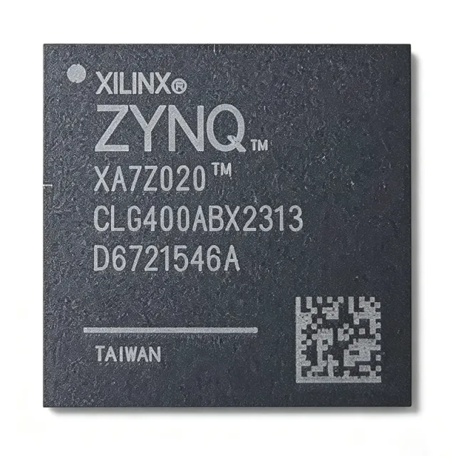
XC7Z020-2CLG484I - Zynq-7000 SoC 85K Logic Cells | AMD
XC7Z020-2CLG484I

XC7Z020-2CLG484I - Zynq-7000 SoC 85K Logic Cells | AMD

The AMD XC7Z020-2CLG484I is a Zynq-7000 All Programmable SoC (AP SoC) integrating a dual-core ARM Cortex-A9 MPCore processor with an Artix-7 class FPGA fabric in a single 484-ball CSPBGA (19x19 mm) package. The processor subsystem runs at up to 766 MHz with CoreSight debug, while the programmable logic provides 85,000 logic cells, 53,200 LUTs, 106,400 flip-flops, 220 DSP slices, and 4.9 Mb of block RAM. A System on Chip (SoC) is an integrated circuit that consolidates processor, memory controllers, peripherals, and programmable hardware on a single substrate. The Zynq-7000 family pairs an ARM-based processing system (PS) with programmable logic (PL) over high-bandwidth AXI interfaces, reducing board space, power, and system complexity versus discrete processor-plus-FPGA solutions. Key features include a DDR3/DDR3L memory controller with ECC, USB 2.0, Gigabit Ethernet, and support for I/O voltages of 1.2V, 1.5V, 1.8V, 2.5V, and 3.3V. The -2 speed grade supports up to 766 MHz PS operation and 200 MHz+ fabric clocking. The industrial temperature grade (-40C to +100C) targets harsh environments. Architecturally, the PS and PL are independent power domains with defined sequencing requirements (VCCINT, VCCAUX, VCCBRAM, VCCO). The device supports partial reconfiguration, allowing dynamic PL updates while the PS continues running. The memory controller delivers robust DDR3/DDR3L with ECC for industrial and automotive-class designs. Typical applications include motor control, industrial automation, software-defined radio, video processing, and embedded vision. The device suits real-time processing with hardware acceleration, such as machine vision and high-speed data acquisition. Design consideration: ensure correct power-rail sequencing and provide a configuration source (QSPI flash) and PS clock; refer to the Zynq-7000 TRM (UG585) for detailed guidance. Pricing from $60.07 (LCSC, as of 2026-08-29).

USD $49,00 En stock
XC8664FRIBEKXUMA1 - 8-bit XC800 MCU, 16KB Flash, 38-TSSOP | Infineon
XC8664FRIBEKXUMA1

XC8664FRIBEKXUMA1 - 8-bit XC800 MCU, 16KB Flash, 38-TSSOP | Infineon

The Infineon XC8664FRIBEKXUMA1 is an 8-bit microcontroller built around the XC800 family 8051-compatible CISC core, integrating 16 KB of on-chip Flash memory, 16 KB (16K x 8) program Flash, and 38-pin TSSOP packaging. It operates from a wide supply range of 2.5 V / 3.3 V / 5 V and runs the 8051 core up to 86 MHz (with peripheral domain scaling at 26.67 MHz per the Hotenda listing). According to the manufacturer datasheet, this IC is the first product of a new and advanced 8-bit uC family (XC8oo family), combining a high-performance 8051 core with on-chip Flash memory and powerful on-chip peripherals. An 8-bit microcontroller (MCU) is a single-chip computer that integrates a CPU, RAM, non-volatile program memory, and peripherals such as timers, ADC, and communication interfaces. The 8051 CISC architecture, originally introduced by Intel in 1980, remains one of the most widely deployed embedded cores worldwide and underpins the hypernym hierarchy 8051 -> 8-bit MCU -> microcontroller -> embedded processor -> semiconductor. The XC8664FRIBEKXUMA1 belongs to Infineon's XC866 sub-family, which is targeted at cost-sensitive industrial and automotive body applications requiring deterministic 8-bit performance. Key differentiating features include a TSSOP-38 footprint with gull-wing leads, automotive temperature grade, integrated 16 KB Flash that supports in-application programming, an on-chip ADC and Capture/Compare Unit (CCU6), and a MultiCAN node for automotive networking. The 86 MHz core clock enables high-throughput bit-manipulation routines typical of motor-control and sensor-interface code, while the wide 2.5 V to 5 V supply range simplifies integration into 3.3 V and 5 V mixed-rail systems without external level shifters. The architecture pairs the standard 8051 instruction set with an XC800-specific peripheral set, including the MultiCAN module, the CCU6 motor-control timer, and a 10-bit ADC with up to eight channels. The wide operating voltage window (2.5 V to 5 V) is a defining trait of the XC8oo family and removes the need for separate voltage regulators in many 3.3 V or 5 V designs. Internal PLL, oscillator, and brown-out circuitry further reduce the external BOM. Typical applications include automotive body electronics, sensor interface modules, low-end motor control, and industrial control. The on-chip MultiCAN node makes the part particularly attractive for in-cabin nodes communicating over a CAN bus at 100 kbit/s to 1 Mbit/s. Designers should note that this part is in the older XC8xx family; current Infineon 8-bit roadmaps have shifted to the XC2000 and AURIX families, so lifecycle planning is recommended before committing to long-life designs.

USD $2,05 En stock
XMC1301Q040F0008ABXUMA1 - 32MHz Cortex-M0 MCU, 8KB Flash | Infineon
XMC1301Q040F0008ABXUMA1

XMC1301Q040F0008ABXUMA1 - 32MHz Cortex-M0 MCU, 8KB Flash | Infineon

The Infineon XMC1301Q040F0008ABXUMA1 is a 32-bit ARM Cortex-M0 industrial microcontroller from the XMC1000 family, clocked at 32 MHz with 8 KB of Flash and 16 KB of SRAM, housed in a PG-VQFN-40-13 package (40-pin VQFN, 5x5 mm) with an exposed pad. It integrates the MATH co-processor (CCU6, two Capture/Compare Units) targeted at digital power conversion and industrial motor control, while retaining the ARM Cortex-M0 instruction set for software portability across the XMC family. An ARM Cortex-M0 microcontroller (MCU) is a 32-bit microprocessor core built around the von Neumann architecture with a Thumb-2 instruction set subset, optimized for minimal silicon area and ultra-low active power consumption. The XMC1000 family sits in Infineon's industrial MCU hierarchy: Cortex-M0 (XMC1000) -> Cortex-M3 (XMC4000) -> Cortex-M4F (XMC4500) -> 32-bit industrial microcontrollers, typically used where 8-bit legacy designs cannot deliver the required computational throughput, deterministic timing, or peripheral integration for power-electronic feedback loops. Key features include the CCU6 peripheral for PWM generation with dead-time insertion and emergency stop, a 12-bit A/D converter with up to 12 channels for current/voltage sensing, MATH coprocessor hardware divide, peripheral clock support up to 64 MHz, and a supply voltage range of 1.8 V to 5.5 V. The 32 MHz CPU frequency combined with the deterministic CCU6 timer cluster makes this device well-suited to the digital control loop bandwidth demanded by 100 kHz-class switch-mode power supplies (SMPS) and low-power field-oriented motor control. The architecture is a single-core Cortex-M0 with on-chip Flash, single-cycle multiplier (32-bit result), an AHB-APB peripheral bridge, and Infineon-specific peripherals including the HRPWM (high-resolution PWM) module and a hardware CRC engine. The MATH coprocessor accelerates 32-bit divide and saturation arithmetic for SMPS compensation networks and Clarke/Park transforms on small BLDC motors. Typical applications include digital power supply PFC and PFC+LLC controllers, low-end BLDC/PMSM sensorless fan pumps, LED lighting drivers, and consumer/industrial sensor conditioning. The wide operating voltage range and on-chip peripherals make it popular in 24V industrial sensor hubs and appliance sub-modules that previously relied on discrete 8-bit microcontrollers. When designing with the XMC1301Q040, ensure the exposed thermal pad is soldered to a ground copper pour of at least 50 mm² to meet the theta_JA specified in the datasheet. The CCU6 dead-time register must be loaded before enabling the PWM outputs to avoid shoot-through on a half-bridge. This page synthesizes distributor pricing from DigiKey/Mouser/LCSC, XAIPART partner dropshipping stock levels, and practical design notes that complement the manufacturer's 78-page datasheet with curated cross-references and lifecycle guidance.

USD $1,16 En stock