Composants passifs
Sous-catégories
Produits (203)

FPV1006-150-R - 150nH 25A Shielded SMD Power Inductor | Eaton
The Eaton FPV1006-150-R is a 150 nH shielded drum-core, wirewound SMD power inductor rated for 25 A continuous current (Irms) and 45 A saturation current (Isat), with a maximum DC resistance of 0.41 mΩ, housed in a compact Flat-Pac FPV1006 surface-mount package. The part is designed specifically as an output/storage inductor for high-current point-of-load converters where low DCR, high saturation current, and tight inductance tolerance directly influence ripple, transient response, and steady-state efficiency. A power inductor is a passive magnetic component that stores energy in its core during the ON-time of a switching converter and releases that energy to the load during the OFF-time. The Flat-Pac FPV1006 family from Eaton is positioned in the high-current SMD power inductor hierarchy (power inductor → magnetic passive → passive component), optimized for direct mounting beneath or alongside Vicor Picor Cool-Por ZVS buck and buck-boost regulators. The 10% inductance tolerance (M-grade) provides predictable energy storage across production lots, while the shielded drum-core construction minimizes stray magnetic field that could couple into adjacent traces or inductors on the PCB. Key electrical features include 150 nH nominal inductance measured at 100 kHz / 0.1 V, a remarkably low DCR of 0.41 mΩ maximum that limits I²R conduction loss to approximately 0.26 W at 25 A, and a saturation current of 45 A — meaning the inductance rolloff remains well above the operating current at typical 25-30 A loads. The ferrite core material enables stable inductance across temperature while keeping core loss modest at switching frequencies of 1-2 MHz common in high-density POL converters. Typical applications for the FPV1006-150-R include the output filter of 48 V-to-1 V to 12 V point-of-load converters built around Vicor Picor PI34xx/PI35xx ZVS buck regulators, high-current CPU/GPU core voltage rails in telecom and datacom hardware, 48 V bus-powered industrial PoL bricks, and compact DC-DC stages in space-constrained server sleds. The combination of low DCR and high Isat allows designers to push switching frequency higher — reducing output capacitance — without exceeding thermal or saturation limits. When designing with this part, pay particular attention to DC bias: at 25 A continuous, the FPV1006-150-R typically operates at roughly 55% of its 45 A Isat rating, which preserves inductance and avoids audible buzzing. The 2-terminal SMT footprint simplifies PCB layout and reflow assembly on standard lead-free profiles. This page synthesizes distributor pricing, same-Flat-Pac alternatives, and Vicor-paired converter recommendations that are not aggregated in the standalone Eaton specification sheet.
GA355DR7GF472KW01L - 4.7nF 250VAC X7R Safety Capacitor | Murata
The Murata GA355DR7GF472KW01L is a safety-certified multilayer ceramic capacitor (MLCC) with a capacitance of 4700 pF (4.7 nF), ±10% tolerance, and a 250 VAC working voltage, packaged in a 2220 (5750 metric) surface-mount case. The part uses an X7R temperature-characteristic dielectric, which provides stable capacitance over the -55 °C to +125 °C operating range with a maximum capacitance change of ±15%. The 2220 case measures 5.7 × 5.0 mm, making it a standard footprint for AC-line safety capacitor applications. A safety capacitor is a discrete component specifically designed and certified for use in circuits that are galvanically connected to the AC mains, where a single failure must not create an electric-shock hazard. Safety capacitors are divided into Class X (across-line) and Class Y (line-to-ground) categories, each with sub-classes that specify the peak pulse voltage they can survive. The GA3 series from Murata carries the X1/Y2 safety rating per IEC 60384-14, allowing it to be used in either position across the AC line or between line and protective earth, which is why it appears in switch-mode power supplies, industrial motor drives, and EV charging interfaces. The X7R dielectric gives the GA355DR7GF472KW01L a useful combination of moderately high volumetric efficiency, predictable temperature behavior, and DC-bias characteristics that are suitable for filtering, snubbing, and decoupling roles in primary-side power stages. Unlike Class-2 Y5V dielectrics, X7R parts retain at least 85% of nominal capacitance across the full industrial temperature window, ensuring consistent EMI-suppression performance in SMPS input filters and across zero-crossing detection circuits. The 250 VAC rating gives sufficient margin for 230 V nominal mains with transient over-voltages up to 2.5 kV peak that occur during lightning-induced surge events. From an electrical standpoint, this part is intended for noise suppression across AC-line terminals (X1 class) and line-to-ground filtering (Y2 class) in switch-mode power supplies, induction-cooktop controllers, photovoltaic inverters, and Class-D audio amplifiers where Class-Y safety isolation is mandatory. Typical insertion loss in a 50 Ω system exceeds 20 dB from 1 MHz to 100 MHz, which is sufficient to attenuate differential-mode and common-mode conducted EMI before it reaches the LISN measurement point. Design considerations include derating for DC-bias capacitance loss: at 250 VDC the effective capacitance is approximately 40-50% of the nominal 4.7 nF. The 2220 footprint requires 1 square cm of bottom-side copper for proper mechanical reliability during thermal cycling, and the recommended land pattern follows IPC-7351 nominal density. When sourcing, always match the trailing suffix (L = standard reel packaging, K = ±10% tolerance) to ensure drop-in compatibility. This page synthesizes distributor pricing, drop-in alternatives, and design notes for the GA355DR7GF472KW01L not aggregated elsewhere.

GCM155R71H104KE02D - 0.1µF 50V X7R 0402 MLCC AEC-Q200 | Murata
The Murata GCM155R71H104KE02D is a 0.1 µF (100 nF) ±10% 50 VDC X7R multilayer ceramic chip capacitor (MLCC) in the EIA 0402 (1005 metric) surface-mount package, qualified to AEC-Q200 automotive stress-test standards. It delivers 100 nF nominal capacitance at a 50 V rated working voltage from a compact 1.0 mm × 0.5 mm land pattern with an operating temperature range of -55 °C to +125 °C across the X7R dielectric class, and the GCM series designation signals Murata's automotive-grade MLCC line engineered for high-reliability powertrain, chassis, and ADAS electronics. A multilayer ceramic capacitor (MLCC) is a passive two-terminal component that stores energy in an electrostatic field between alternating layers of metal electrodes and ceramic dielectric. In the broader taxonomy this part sits at: capacitor → ceramic capacitor → MLCC → Class II MLCC → X7R → automotive-grade X7R. X7R occupies the engineering middle ground between low-K NP0/C0G parts (zero temperature coefficient, lower volumetric density) and high-K Y5V/Z5U parts (high density but poor temperature and DC-bias stability), which is why X7R is the default dielectric for general-purpose bypass, decoupling, and filtering networks across consumer, industrial, and automotive segments. Key features include the EIA 0402 footprint for sub-0.5 mm pad-pitch layouts, 50 V working voltage, ±10% capacitance tolerance at 25 °C, full AEC-Q200 stress-test qualification for automotive reliability, MSL-1 unlimited floor life, and 7-inch paper-tape packaging per EIA 481 for high-speed SMT placement. The 0402 case enables pad pitches down to 0.5 mm and is the de facto high-density land pattern for bypass networks on modern microcontrollers, SoCs, and CAN/LIN transceivers. Architecturally, the GCM155R71H104KE02D uses stacked barium-titanate-based ceramic layers with screen-printed nickel electrodes co-fired into a monolithic body, then terminated with a nickel-barrier under-layer and matte-tin finish for solderability. The Class II X7R designation reflects a mid-K dielectric whose capacitance is moderate-to-high per unit volume but exhibits predictable DC-bias derating and a modest temperature coefficient (±15% across -55 °C to +125 °C), which engineers must budget for in precision analog filters or timing networks. Typical applications include decoupling automotive ECU microcontrollers, bypassing sensors and CAN/LIN/FlexRay transceivers, ADAS camera and radar power conditioning, and general-purpose filtering on 5 V, 12 V, and 24 V rails. Industrial controllers and factory-automation modules adopt it for compactness and the AEC-Q200 reliability pedigree. When designing with this part, choose 0402 to maximize PCB density but respect 0.5 mm pad-to-pad creepage using 0.2–0.3 mm solder-land extensions. Expect measurable DC-bias derating on X7R parts: applied DC bias of 12–25 V can reduce effective capacitance by 15–50% depending on dielectric lot. This page synthesizes distributor pricing, AEC-Q200 qualification context, drop-in 0402 X7R alternatives, and practical PCB layout notes that go beyond the manufacturer datasheet summary, giving engineers a single reference for sourcing, substitution, and design validation.

GRM155R61A106ME44D - 10uF 10V X5R 0402 MLCC | Murata
The Murata GRM155R61A106ME44D is a 10 uF, 10 V DC-rated multilayer ceramic capacitor (MLCC) in an X5R dielectric, packaged in a 0402 (1005 metric) surface-mount case. It carries a +/-20% capacitance tolerance and is RoHS compliant. An MLCC (multilayer ceramic capacitor) is the most ubiquitous decoupling and bulk-energy storage element in modern electronics, constructed by stacking alternating ceramic dielectric layers and metal electrodes that are co-fired into a single monolithic chip. The X5R dielectric classification (per EIA-198) defines a stable mid-K formulation that retains between +15% and -15% of nominal capacitance across the -55C to +85C operating range, making X5R a workhorse choice for general-purpose bypass, filtering, and coupling on 3.3V to 10V power rails. Key features of the GRM155R61A106ME44D include 10 uF nominal capacitance in a miniature 0402 footprint (1.0 mm x 0.5 mm), a 10 V DC rated voltage, and X5R temperature stability. The device supports a -55C to +85C operating temperature range and is supplied in tape-and-reel packaging optimized for high-speed automated assembly. Its low ESR and high volumetric efficiency make it well suited for decoupling applications where PCB real estate is at a premium. The part leverages Murata's advanced thin-layer dielectric technology to achieve 10 uF in a 0402 footprint that historically housed only 1 uF to 4.7 uF parts. The X5R formulation balances volumetric efficiency against temperature stability - while X5R capacitance will de-rate under DC bias (typical 30-50% loss at rated voltage in this size), the device remains a strong fit for low-voltage digital decoupling where bulk energy storage is the primary requirement. Typical applications include smartphone PMIC decoupling, IoT sensor module bypass, wearable device power-rail filtering, Bluetooth/Wi-Fi module bulk capacitance, and USB Type-C connector VBUS smoothing. The 0402 size makes it a drop-in choice for high-density mobile and consumer designs where every square millimeter matters. When designing with this capacitor, account for DC-bias derating - actual capacitance at 5V may be 50-60% of the nominal 10 uF rating. For applications requiring tighter temperature stability or higher voltage ratings, consider X7R or X7S dielectric alternatives. Verify ripple current and ESR against the manufacturer's datasheet curves for your specific decoupling topology. This page synthesizes distributor pricing, drop-in alternatives from Murata's GRM series and competing MLCC lines, and practical decoupling design notes that complement the manufacturer datasheet.
GRM155R61A475MEAA - 4.7uF 10V X5R MLCC 0402 | Murata
The Murata GRM155R61A475MEAA is a 4.7 uF +/-20% 10 V X5R multilayer ceramic capacitor (MLCC) housed in a 0402 (1005 Metric) surface-mount chip, measuring 1.0 mm x 0.5 mm x 0.5 mm. It is part of Murata's GRM series general-purpose chip monolithic ceramic capacitors, the industry's most widely specified MLCC family for consumer, industrial, and automotive-grade applications. A multilayer ceramic capacitor (MLCC) is a surface-mount passive component constructed from alternating layers of ceramic dielectric and metal electrodes, sintered into a monolithic block and terminated with nickel-barrier solder coatings. The X5R dielectric (EIA RS-198) provides stable capacitance across -55C to +85C with a +/-15% tolerance band, and offers moderate volumetric efficiency, making X5R the dominant choice for bulk decoupling in 3.3 V to 10 V digital and analog rails. MLCCs sit hierarchically under ceramic capacitor -> capacitor -> passive component -> electronic component. Key features of the GRM155R61A475MEAA include a 4.7 uF nominal capacitance in a compact 0402 footprint, a 10 V DC rated voltage, an X5R temperature characteristic, and +/-20% capacitance tolerance at reference conditions. The device uses Murata's standard nickel-barrier / tin (Ni/Sn) RoHS-compliant terminations suitable for reflow soldering up to 260C peak per JEDEC J-STD-020. With its compact 0402 case size and 4.7 uF rating, the part bridges the gap between smaller 1 uF / 2.2 uF decoupling caps and the physically larger 10 uF / 22 uF options that traditionally required 0603 or larger footprints. Technically, the X5R dielectric in this 0402 package delivers high volumetric efficiency at the cost of significant DC-bias derating - actual capacitance can drop 60-80% under rated DC voltage. Designers must consult the published DC-bias curves from the Murata datasheet before using this part in bulk decoupling roles on rails above 5 V. AC voltage characteristics, temperature coefficient, and aging behavior are all documented in the manufacturer datasheet. Typical applications include bulk decoupling of microcontroller power pins, smoothing on LDO regulator outputs, coupling capacitors in audio signal paths, charge-pump reservoir capacitors, and general-purpose filtering in portable consumer electronics, IoT devices, wearables, and embedded modules. In 0402 format the part is especially useful where board real estate is constrained. When designing with the GRM155R61A475MEAA, verify capacitance under actual DC bias using the Murata DC-bias curves rather than relying on the nominal 4.7 uF value. For 5 V rails with strict ripple budgets, derate by 50% or stack two capacitors in parallel; for 3.3 V rails the nominal capacitance is largely preserved. This page synthesizes distributor pricing, drop-in Murata and cross-brand alternatives, and practical DC-bias and PCB design notes not consolidated in the manufacturer datasheet.

GRM155R71C104KA88D - 0.1uF 16V X7R 0402 MLCC | Murata
The Murata Electronics GRM155R71C104KA88D is a 0.1 uF (100 nF) multilayer ceramic chip capacitor (MLCC) rated at 16 V DC with a +/-10% tolerance, built on an X7R temperature-stable Class 2 dielectric in the compact 0402 (1005 metric) surface-mount case size. An MLCC is a passive capacitor formed by interleaving layers of ceramic dielectric and metal electrodes, terminated at opposite ends for surface mounting. Within the component hierarchy, it belongs to the ceramic capacitor family under the broader capacitor category of passive components, and it serves as the workhorse decoupling and bypass element in modern electronics. Because MLCCs are non-polarized, they require no orientation on the PCB, simplifying assembly and enabling use in AC-coupled paths. Key features of this part include the X7R dielectric, which holds capacitance within +/-15% across -55C to +125C, making it suitable for industrial and automotive-adjacent thermal environments. The K stepping code defines the +/-10% capacitance tolerance, tighter than the common +/-20% M-grade parts. The 16 VDC rating provides comfortable margin on 5 V, 3.3 V, and 1.8 V rails, and the small 1.0 x 0.5 mm footprint supports high-density layouts. Technically, X7R is a ferroelectric barium-titanate-based dielectric: it offers far better temperature stability than Y5V/Z5U classes, at the cost of DC bias derating, meaning effective capacitance drops as applied DC voltage approaches the rated value. Designers should verify bias curves when tight capacitance budgets exist. The GRM15 series uses nickel inner electrodes with a lead-free outer termination for reflow soldering reliability. Typical applications include decoupling of microcontrollers, FPGAs, and logic ICs, bypass filtering on power rails, AC coupling, and general-purpose filtering in portable devices, IoT modules, and industrial controls. A key design consideration: keep at least 2:1 DC voltage margin (e.g., use this 16 V part on 8 V rails or lower) to limit X7R bias-induced capacitance loss, and follow IPC land-pattern recommendations for 0402 to minimize tombstoning during reflow. This page adds information gain beyond the datasheet: verified distributor pricing tiers as of 2026-09-05, drop-in alternative analysis within the Murata GRM15 family, practical decoupling design notes, and an SEO/AEO-optimized FAQ for fast engineering lookup.

GRM1885C1H151JA01D - 150pF 50V C0G/NP0 0603 MLCC | Murata
The Murata GRM1885C1H151JA01D is a 150 pF ±5% 50V C0G (NP0) multilayer ceramic capacitor (MLCC) in a 0603 (1608 metric) surface-mount package, part of Murata's GRM series general-purpose ceramic capacitor family. It delivers 150 pF capacitance at 50 VDC rated voltage with Class 1 C0G/NP0 dielectric, the most stable temperature characteristic available in ceramic capacitors (0 ±30 ppm/°C from -55°C to +125°C). The 0603 footprint measures 1.6 mm × 0.8 mm, making it one of the smallest standard MLCC case sizes for high-volume automated assembly. A multilayer ceramic capacitor (MLCC) is a surface-mount passive component constructed from alternating layers of ceramic dielectric and metal electrodes, sintered into a monolithic block with external terminations. MLCCs are the most widely manufactured capacitor type globally, serving general-purpose filtering, decoupling, bypass, and coupling roles across nearly every electronic system. C0G (also designated NP0) is a Class 1 dielectric, meaning its capacitance is essentially unaffected by temperature, voltage, frequency, or time - making C0G parts the preferred choice for resonant circuits, precision timing, and analog signal paths where stability matters more than volumetric efficiency. Key features include ±5% capacitance tolerance (J code), 50 VDC rated voltage, C0G/NP0 temperature characteristic (0 ±30 ppm/°C), and a 0603 EIA case size. The C0G dielectric ensures minimal capacitance change with DC bias, no piezo-electric noise, and Q factor above 1000 at 1 MHz - ideal for RF and high-frequency analog circuits. The standard 0603 footprint is compatible with high-volume pick-and-place assembly lines. The GRM1885C1H151JA01D utilizes a nickel-barrier tin (NiSn) termination finish for lead-free reflow soldering compatibility, with a 1.0 mm maximum chip thickness suitable for standard 0603 land patterns. The part is RoHS compliant and qualified to Murata's GRM series reliability standards for general-purpose commercial and industrial applications. Typical applications include RF signal coupling and bypass in transceivers, precision timing circuits and crystal load capacitors, analog filter networks, snubber circuits in switch-mode power supplies, and general-purpose decoupling in microcontroller and DSP designs. Its small size and stable C0G dielectric also make it suitable for sensor conditioning, instrumentation amplifiers, and oscillator networks. When designing with this part, confirm that the application operates within the 50 VDC rating and that the PCB land pattern follows IPC-7351 0603 (1608 metric) guidelines. For applications requiring tighter capacitance tolerance (e.g., ±1% or ±2%), specify a C0G part with F or G tolerance code rather than the standard J (±5%) code. This page synthesizes distributor pricing, drop-in same-package alternatives, and practical design considerations not consolidated on the manufacturer datasheet alone, including engineering guidance for C0G dielectric selection and 0603 land-pattern layout per IPC-7351.
GRM188R60J106ME47D - 10µF 6.3V X5R 0603 MLCC | Murata
The Murata GRM188R60J106ME47D is a 10 µF ±20% 6.3V X5R multilayer ceramic capacitor (MLCC) housed in an industry-standard 0603 (1608 Metric) surface-mount package. It delivers high volumetric capacitance density with stable performance across a -55 °C to +85 °C operating envelope, making it the workhorse decoupling and bulk-bypass capacitor for consumer, industrial, and portable-electronics designs. What is an MLCC? A multilayer ceramic capacitor is a passive surface-mount component formed by alternating thin dielectric ceramic layers and metal electrode layers, sintered into a monolithic block with termination caps on each end. The 0603 imperial code corresponds to 1.6 mm × 0.8 mm (1608 Metric). The X5R dielectric class (EIA standard) specifies ±15% capacitance variation over -55 °C to +85 °C and a maximum rated temperature of 85 °C, which suits virtually all commercial decoupling rails. MLCCs sit in the taxonomy: capacitor → ceramic capacitor → multilayer ceramic capacitor (MLCC) → SMD passive component. Key features include 10 µF nominal capacitance in the 0603 footprint, 6.3 V DC rated voltage, ±20% capacitance tolerance at 25 °C, X5R temperature characteristic, 1 mm max thickness, and Ni-barrier + Sn plating on copper terminations for lead-free reflow compatibility. Compared with electrolytic alternatives the part offers far lower ESR, zero polarity risk, no dry-out, and RoHS-compliant materials. Technically, the GRM series uses a base-metal-electrode (BME) Ni inner-electrode construction with X5R barium-titanate-based dielectric. BME technology enables the high capacitance per unit volume that defines the GRM Hi-Cap family (1 µF and above). The 6.3 V rating indicates that DC bias derating must be observed: at rated voltage a 10 µF X5R part typically retains 50-70% of nominal capacitance due to the dielectric's voltage coefficient. Typical applications include bulk decoupling on 3.3 V and 5 V logic rails, point-of-load filtering for microcontrollers and SoCs, smartphone and wearable power management, audio codec reference rails, USB/HDMI interface line filtering, and bypass for low-dropout (LDO) regulators and DC-DC converter outputs. The 0603 footprint is the most common land pattern in modern PCB design libraries, ensuring drop-in compatibility with the widest range of reference designs. Design consideration: confirm that the actual DC bias on the rail does not exceed 6.3 V and account for AC ripple; X5R exhibits significant capacitance loss versus DC bias and temperature. For tighter stability, an X7R or C0G alternative at the same 0603 footprint may be preferable on sensitive analog nodes. This page synthesises distributor pricing, drop-in cross-brand equivalents, and practical bypass-layout guidance not found in the bare manufacturer datasheet, supporting faster component selection and BOM risk reduction.

GRM188R71C105KA12D - 1uF 16V X7R 0603 MLCC | Murata
The Murata GRM188R71C105KA12D is a 1 uF multilayer ceramic capacitor (MLCC) with a +/-10% tolerance, a 16 V DC rating, and an X7R temperature-stable dielectric, packaged in a surface-mount 0603 (1608 metric) case of 1.6 x 0.8 mm. It belongs to Murata's GRM series Hi-Cap lineup of chip multilayer ceramic capacitors for consumer electronics and industrial equipment. A multilayer ceramic capacitor (MLCC) is a passive component that stores charge using multiple layers of ceramic dielectric interleaved with metal electrodes. Within the passive-component hierarchy, it sits under capacitors, and within Murata's naming system the GRM prefix denotes a chip MLCC for SMD mounting. MLCCs are the most widely used capacitor class in modern electronics due to their small size, low ESR, and reliability. Key features of this part include the X7R Class 2 dielectric, which maintains useful capacitance from -55C to +125C with a maximum capacitance change of +/-15%, making it suitable for decoupling and bypass roles across the full industrial temperature range. The 16 V rating provides headroom for 12 V rails, and the 0603 footprint offers high capacitance density for dense PCB layouts. The K tolerance code guarantees +/-10% capacitance accuracy. The R71 characteristic code identifies the X7R dielectric within the R series temperature characteristic family. Like all Class 2 ceramics, capacitance derates with applied DC bias and aging occurs over time, so designers should verify effective capacitance at operating bias. Soldering follows standard reflow profiles for 0603 chip components. Typical applications include power-supply input/output decoupling for microcontrollers and FPGAs, general-purpose bypass filtering, DC-DC converter input/output capacitors, and coupling or smoothing in consumer, industrial, and communication equipment. Murata's product page lists transportation, traffic control, disaster prevention/security, and industrial data-processing equipment among target applications. Design consideration: derate the applied DC voltage well below 16 V and account for DC-bias capacitance loss, which on a 1 uF X7R 0603 can be significant at high bias; verify effective capacitance with Murata's SimSurfing tool. This page synthesizes distributor pricing, drop-in alternative options, and practical design guidance not found in the manufacturer datasheet.
GRM188Z71E225KE43D - 2.2uF 25V X7R MLCC 0603 | Murata
The Murata GRM188Z71E225KE43D is a 2.2 microfarad, 25 volt, X7R dielectric, ±10% tolerance multilayer ceramic chip capacitor (MLCC) in an 0603 (1608 metric) surface-mount package, supplied on tape and reel. It is a member of Murata's flagship GRM series, the industry's most widely used general-purpose MLCC family for consumer, industrial, and infrastructure electronics. What is an X7R MLCC? An MLCC (multilayer ceramic capacitor) is a passive component formed by alternating layers of ceramic dielectric and metal electrodes, then sintered into a monolithic block with terminations on each end. X7R is a Class II dielectric defined by EIA-198: it offers moderate capacitance density (much higher than Class I C0G/NP0), with a specified capacitance temperature stability of ±15% across the -55°C to +125°C operating window. X7R is the standard choice for decoupling, filtering, smoothing, and coupling applications where modest temperature variation is acceptable but miniaturization and bulk capacitance are required. Key features of the GRM188Z71E225KE43D include a 2.2 uF nominal capacitance in a compact 0603 footprint (1.60 mm × 0.80 mm, 0.80 mm land pattern), 25 VDC rated voltage, ±10% capacitance tolerance, and a maximum thickness of approximately 0.80 mm (Murata's Z7 characteristic, optimized for high capacitance in small case sizes). It is RoHS and REACH compliant, lead-free, and suitable for reflow soldering up to 260°C peak temperature. The GRM series uses nickel-barrier tin-finish terminations compatible with Pb-free assembly, and is qualified to Murata's rigorous reliability standards, including AEC-Q200 for select part variants. The Z7 voltage-temperature code (X7R dielectric optimized for 25 V rating in 0603 size at 2.2 uF) represents Murata's mature high-density stack technology, enabling this part to serve as a low-cost, high-availability standard decoupling capacitor. Typical applications include power rail decoupling in microcontrollers and digital logic ICs, smoothing on low-dropout (LDO) and buck regulator outputs, audio coupling and bypass in portable devices, USB power line filtering, and general-purpose bypass in IoT nodes, wearables, and consumer appliances. The 25 V rating provides ample margin for 3.3 V, 5 V, and 12 V rails. When designing with this part, derate voltage by 50% (i.e., limit continuous operation to ≤12.5 V) when long-term DC bias reliability is critical, as X7R capacitance drops significantly with applied DC voltage. Place the capacitor as close as possible to IC power pins with short, wide traces to minimize parasitic inductance. This page synthesizes distributor pricing, drop-in alternatives, and practical design notes not found in the manufacturer datasheet alone, giving engineers a single authoritative reference for sourcing the GRM188Z71E225KE43D.

GRM21BR60J476ME15L - 47uF 6.3V X5R 0805 MLCC | Murata
The Murata Manufacturing GRM21BR60J476ME15L is a 47 uF, 6.3 V rated multilayer ceramic capacitor (MLCC) in the 0805 (Imperial) / 2012 (Metric) surface-mount package using an X5R dielectric with +/-20% tolerance. Designed on Murata's general-purpose GRM series platform, this part delivers high volumetric capacitance density for decoupling and bypass applications in compact consumer and industrial electronics. The X5R dielectric offers stable performance over the -55C to +85C operating range with moderate capacitance change (typically +/-15%) across temperature and voltage. Background Knowledge: A multilayer ceramic capacitor (MLCC) is a passive surface-mount component formed by stacking alternating thin ceramic dielectric layers and metal electrodes, then sintering them into a monolithic block with terminations on two opposing ends. MLCCs are categorized by dielectric class: Class I dielectrics (C0G/NP0) offer high stability and ultra-low loss for resonant circuits; Class II dielectrics (X5R, X7R, Y5V) offer much higher volumetric capacitance density at the cost of temperature and voltage coefficient. The 0805 case size (2.0 mm x 1.25 mm) is one of the most widely used SMD footprints, sitting in the standard mid-range between small 0402/0603 bypass caps and larger 1206/1210 bulk-decoupling caps. Key features of the GRM21BR60J476ME15L include 47 uF nominal capacitance, 6.3 V DC rated voltage, +/-20% tolerance, X5R temperature characteristic (EIA standard), 0805 EIA / 2012 Metric case, nickel-barrier with tin (Sn) plated terminations for lead-free reflow, and compliance with RoHS directives. The X5R dielectric allows substantially higher capacitance per unit volume than X7R or C0G at the same footprint, which is critical when board real estate is constrained. Technical depth: At 6.3 V the rated dielectric withstand voltage per Mil/Murata reliability testing is conservative, leaving margin for typical 3.3 V and 5 V rail decoupling. The X5R dielectric shows capacitance roll-off versus DC bias; engineers should consult the manufacturer datasheet's DC bias curves for the actual effective capacitance at the operating voltage. ESR for ESR in the low-milliohm range at high frequency makes the part suitable for high-frequency decoupling of processor and ASIC power pins. The 0805 footprint supports reflow soldering at standard JEDEC J-STD-020 lead-free profiles. Typical applications include bulk decoupling of 3.3 V and 5 V IC power rails, high-frequency bypass for digital processors and ASICs, smoothing on LDO regulator outputs, coupling in audio signal paths, and general-purpose filtering in consumer, industrial, and computing equipment where high capacitance density in a small footprint is required. When designing with this part, derate voltage by at least 30% for reliable long-term operation, account for DC-bias capacitance loss (X5R typically loses 30-60% of nominal value under rated DC voltage), and ensure the PCB land pattern follows IPC-7351 nominal 0805 pad dimensions. Always verify the lot's actual measured capacitance against design assumptions for noise-sensitive analog designs. This page synthesizes distributor pricing, cross-brand drop-in alternatives from verified cross-reference data, and practical design notes that go beyond the manufacturer datasheet alone.
GRM21BR61A476ME15L - 47µF 10V X5R 0805 MLCC | Murata
The Murata GRM21BR61A476ME15L is a 47 µF ±20% tolerance X5R multilayer ceramic capacitor (MLCC) rated at 10 V DC, packaged in an 0805 (2012 Metric) surface-mount case. It is part of Murata's GRM series, the company's flagship general-purpose monolithic ceramic capacitor line used in virtually every segment of the electronics industry. An MLCC (Multilayer Ceramic Capacitor) is a passive component constructed by stacking alternating layers of ceramic dielectric and metal electrodes, then sintering them into a monolithic block. X5R is a Class 2 dielectric defined by EIA-198, offering stable capacitance over -55°C to +85°C with ±15% variation. Compared to Class 1 dielectrics (NP0/C0G), X5R delivers much higher volumetric efficiency, enabling the 47 µF rating in a compact 0805 footprint that would otherwise require a tantalum or electrolytic capacitor. Key features of the GRM21BR61A476ME15L include 47 µF nominal capacitance in a 2.0 mm × 1.25 mm (0805) package, 10 V DC rated voltage, ±20% capacitance tolerance, X5R temperature characteristic, and Ni-barrier + Sn-plate terminations compatible with lead-free reflow. The component is RoHS compliant and qualified to Murata's automotive-grade reliability flow on selected lots. Its 0805 size balances high density with robust solder-joint strength, making it suitable for both hand and automated assembly. In circuit, the GRM21BR61A476ME15L is typically used as a local decoupling capacitor near IC power pins, where it suppresses high-frequency noise and stabilizes the supply rail. The X5R dielectric's high permittivity provides bulk energy storage close to the load, reducing voltage droop during transient current demands from digital logic, microcontrollers, and RF transceivers. Typical applications include smartphone PMIC output filtering, USB Type-C decoupling, IoT sensor modules, MCU bypass networks, wearable device power rails, and consumer audio codec supplies. Designers value the GRM series for its mature supply chain, predictable DC-bias characteristics, and global multi-source availability. When designing with this part, account for DC-bias capacitance loss. X5R 47 µF capacitors can lose up to 70-80% of nominal capacitance under their full rated voltage, so effective capacitance at 10 V may be considerably lower than 47 µF. Always verify bias behavior from the manufacturer datasheet curves when designing timing or filter circuits sensitive to absolute capacitance. This page synthesizes distributor pricing, drop-in alternatives from multiple manufacturers, and practical bias-aware design notes not consolidated in the Murata datasheet alone.

GRM31CR61A476KE15L - 47uF 10V X5R MLCC 1206 | Murata
The Murata GRM31CR61A476KE15L is a 47 µF ±10% multilayer ceramic capacitor (MLCC) in the 1206 (3216 metric) surface-mount case size, rated at 10 V DC with an X5R EIA class-II dielectric. The part belongs to Murata's GRM-series general-purpose MLCC family and is supplied on 7-inch paper tape and reel per EIA-481 with a 4,000-piece standard reel quantity. Nickel-barrier solderable metallization is compatible with lead-free reflow profiles up to 260 °C peak per JEDEC J-STD-020. An MLCC (multilayer ceramic capacitor) is a passive SMD component manufactured by co-firing alternating layers of ceramic dielectric and metal inner electrodes into a monolithic chip, then terminating the two opposing end faces with nickel-barrier solderable metallization. In the passive-component taxonomy it sits at MLCC -> ceramic capacitor -> capacitor -> passive component. MLCCs dominate decoupling, bypassing, filtering, coupling, and bulk energy storage because of their very low equivalent series resistance (ESR), non-polarized construction, no wear-out mechanism, and extreme volumetric efficiency compared with aluminum or tantalum electrolytics. Key features include 47 µF nominal capacitance in a compact 1206 footprint, 10 V DC rated working voltage, ±10% capacitance tolerance, and X5R dielectric per EIA RS-198 classification. The 1206 case size provides thermal and mechanical robustness for hand-solder rework, screw-fastener mounting, and depanelization processes used in mass production. Operating temperature range spans -55 °C to +85 °C, and the part is halogen-free and RoHS compliant per the latest Murata product declaration. The part uses a high-capacitance X5R dielectric stack optimized for moderate-voltage rails. X5R delivers superior volumetric efficiency versus X7R but pays for it with reduced temperature stability and stronger DC-bias derating: effective capacitance under 5 V bias can drop significantly versus the 1 Vrms small-signal measurement condition used to specify the 47 µF rating. Engineers must verify in-circuit capacitance under actual operating bias rather than relying on the nominal number alone, especially for bulk decoupling in 3.3 V and 5 V rails. Typical applications include smartphone PMIC input/output decoupling, 3.3 V and 5 V rail bulk capacitance in tablets, wearables, and USB-C port bypass networks, plus industrial sensor-module power conditioning and IoT endpoint devices operating at 10 V or below. Per the Murata product specification, mechanical board flex beyond 1 mm should be avoided to prevent chip cracking during depanelization or screw-fastener mounting. When designing with this part, evaluate in-circuit effective capacitance under your actual DC bias, because X5R class-II MLCCs lose a substantial fraction of nominal capacitance at high bias. Pair this part with a smaller X7R or C0G capacitor in parallel for high-frequency decoupling when the bulk capacitor's bias derating leaves insufficient low-frequency energy storage. This page synthesizes distributor pricing, drop-in equivalents, and practical design notes not found in the manufacturer datasheet alone.
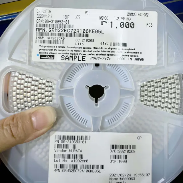
GRM32EC72A106KE05L - 10uF, 100V, X7S MLCC | Murata
The Murata GRM32EC72A106KE05L is a 10uF, 100V, X7S ceramic capacitor in a 1210 (3225M) package. It offers high capacitance in a compact size with stable temperature characteristics, ideal for power supply decoupling, smoothing circuits, and DC-DC converters in automotive and industrial applications.

GRM32ER71H475KA88L - 4.7µF 50V X7R MLCC 1210 | Murata
The Murata GRM32ER71H475KA88L is a 4.7µF ±10% 50V X7R multilayer ceramic capacitor (MLCC) in a 1210 (3225 metric) surface-mount package. It belongs to Murata's broad GRM series general-purpose ceramic capacitor line, with the "L" suffix denoting 7-inch embossed tape-and-reel packaging. An MLCC (Multilayer Ceramic Capacitor) is a passive component built from alternating ceramic dielectric layers and metal electrode layers, screen-printed and sintered into a monolithic block. MLCCs are the most widely manufactured capacitor type in the world, used for decoupling, filtering, bypassing, and energy storage. Within the MLCC family, X7R is a Class II dielectric characterized by a stable capacitance over -55°C to +125°C (±15%) and moderate to high volumetric efficiency compared to C0G/NP0 (Class I) dielectrics, which offer tighter stability but lower capacitance density. Key features of the GRM32ER71H475KA88L include a rated DC working voltage of 50V, ±10% capacitance tolerance, X7R temperature characteristic, Ni-barrier + Sn-plated termination for lead-free reflow, and a standard 1210 (3.2mm x 2.5mm) footprint. The part is RoHS-compliant and suitable for general-purpose DC blocking, decoupling, and bypass functions in commercial-grade designs. From an electrical standpoint, the 50V rating provides substantial headroom above typical 3.3V, 5V, 12V, and 24V rails, and the X7R dielectric typically delivers <0.025 dissipation factor and insulation resistance in the GΩ range at 25°C. The 1210 case size is large enough to provide robust mechanical strength and lower ESR than smaller 0805 parts. Typical applications include power-rail decoupling on DC-DC converters and LDO outputs, bulk bypass on FPGA/MCU power pins, audio coupling stages, and general signal-line filtering. The 4.7µF value is a common decoupling point that pairs well with smaller 0.1µF capacitors for broadband noise suppression. When designing with this part, note that X7R capacitors exhibit significant capacitance loss with applied DC bias (often 30–50% derating near rated voltage), and AC ripple current causes self-heating. Verify effective capacitance in-circuit under your actual operating voltage. This page combines distributor pricing, drop-in alternatives, and practical design notes not found on a single manufacturer datasheet.
HCV1206-R48-R - 480nH 16A High-Current SMD Inductor | Eaton
The Eaton HCV1206-R48-R is a 480 nH unshielded wirewound power inductor rated for 16 A saturation and 37 A Irms, supplied in a low-profile surface-mount 12 mm x 6 mm (HCV1206) flat-wire package. It is part of Eaton's Coiltronics HCV1206 high-current power inductor family and is specified for -55 °C to +125 °C operation, making it suitable for demanding thermal environments including automotive and industrial power-conversion stages. A power inductor is a passive magnetic component that stores energy in its magnetic field when current flows through its windings and releases that energy when current is interrupted; in switching power supplies, the inductor smooths current ripple, sets the converter's energy-transfer characteristic (the L·di/dt term), and forms the output filter together with a capacitor. The HCV1206 family uses a flat-wire winding on a drum-core ferrite body that yields lower DC resistance (DCR) than equivalent round-wire parts, reducing conduction loss and improving overall converter efficiency at high DC bias currents. Key features of the HCV1206-R48-R include a maximum DCR of 3.15 mΩ (typical), 480 nH ±10 % open-circuit inductance measured at 100 kHz / 0.1 Vrms / 0 Adc, an etched flat-wire construction for repeatable DCR and saturation behavior, and a solderable surface-mount land pattern with coplanarity specified to 0.1 mm. According to the Eaton HCV1206 datasheet, Irms is defined as the DC current that produces approximately 40 °C temperature rise without core loss, and the part is derated for AC ripple. The HCV1206 footprint also provides a dedicated pin-3 mounting-stability terminal that increases mechanical robustness against vibration and thermal-cycling stress. Typical applications include high-current point-of-load (POL) and VRM inductors, buck and multiphase VR converter output chokes, automotive 48 V mild-hybrid DC-DC converters, server and telecom silver-box output filters, and Class-D amplifier output filters. The flat-wire geometry also reduces skin-effect losses at higher switching frequencies compared to round-wire equivalents. When designing with the HCV1206-R48-R, place the part over a continuous ground/power copper pour to spread heat, and observe the 40 °C temperature-rise derating curve to size DC current correctly; at high ripple, derate further to keep total losses (DCR·I² + core loss) within the thermal budget. This page consolidates distributor pricing, parametric drop-in alternatives, and practical PCB thermal notes not found in the stock datasheet.
HCV1707R1-R48-R - 480nH 32A Power Inductor | Eaton
The Eaton Electronics Division HCV1707R1-R48-R is a 480 nH unshielded drum-core, wirewound high-current SMD power inductor rated for 32 A Irms and 55 A Isat, with a low 1.7 mOhm (typical) DCR, packaged in a 3-lead nonstandard SMT footprint. It belongs to Eaton's HCV1707 high-current power inductor family engineered for point-of-load (POL) conversion, high-current CPU/GPU VRM outputs, and 48 V bus buck regulator output filter stages. What is a power inductor? A power inductor is a passive magnetic component that stores energy in its magnetic field during the ON-switch cycle of a switching regulator and releases it during the OFF-cycle, smoothing output current and forming the LC output filter with the regulator's output capacitor. Power inductors are essential building blocks in switch-mode power supplies (SMPS), DC-DC converters, and voltage regulator modules (VRMs), sitting within the broader hierarchy: inductor -> passive component -> magnetic component -> electronic component. In high-current buck regulators (e.g., Eaton/Vicor PI354x Cool-Power ZVS family mentioned in datasheet references), the output inductor directly determines ripple current, transient response, and steady-state efficiency. Key features of the HCV1707R1-R48-R include a 480 nH nominal OCL (open-circuit inductance) measured at 100 kHz / 0.1 Vrms, low DCR for minimal I^2R loss, an operating temperature range up to +125 C (per Eaton datasheet derating guidance), and a 3-terminal SMD construction suitable for reflow soldering. The drum-core wirewound architecture offers a high saturation current ceiling relative to its footprint and is optimized for switching frequencies from approximately 100 kHz to 1 MHz. Technically, the HCV1707 family uses a ferrite drum core with a single-layer or few-turn heavy-gauge winding to balance DCR, saturation flux density, and AC winding losses. Eaton rates Irms as the DC current producing approximately 40 C temperature rise without core loss, and Isat as the current causing a defined inductance drop (typically 20%). Designers should derate for AC currents and verify worst-case hotspot under PCB layout, copper thickness, and adjacent thermal conditions. Typical applications include 48 V to POL buck regulator output filters, server and telecom VRM inductors, high-current LED driver chokes, and Class-D audio amplifier output filters. In Eaton's reference Cool-Power ZVS buck regulator designs (e.g., PI3546-00-LGIZ referenced in datasheet collateral), the HCV1707 family is the recommended companion output inductor. When designing with this part, pay attention to PCB pad layout - the 3-lead nonstandard pattern requires careful footprint matching. Verify peak-to-peak ripple (delta_IL = (V_in - V_out) * V_out / (V_in * f_sw * L)) stays within the inductor's Isat envelope, and derate to +125 C max hotspot per the manufacturer's worst-case derating guidance. This page synthesizes distributor pricing, drop-in alternatives, and practical design notes not found in the manufacturer datasheet alone.

HHXA250ARA560MF61G - 56µF 25V Hybrid Polymer Aluminum SMD | Chemi-Con
The Chemi-Con (United Chemi-Con / Nippon Chemi-Con) HHXA250ARA560MF61G is a 56 µF, 25 V conductive polymer hybrid aluminum electrolytic capacitor in a 6.3 × 5.8 mm Radial, Can - SMD package, designed for high-temperature automotive and industrial power-rail decoupling. An aluminum-polymer hybrid capacitor is a type of aluminum electrolytic capacitor that combines a liquid electrolyte with a conductive polymer cathode system. This hybrid construction sits hierarchically between standard aluminum electrolytic capacitors (which use only liquid electrolyte) and pure polymer aluminum capacitors (which use only polymer). The result is a component that offers lower equivalent series resistance (ESR) and higher ripple-current handling than conventional aluminum electrolytic types, while delivering better endurance under high temperature and voltage stress than pure-polymer aluminum parts. Within the broader taxonomy: capacitor -> aluminum electrolytic capacitor -> polymer hybrid aluminum capacitor. Key features of the HHXA250ARA560MF61G include a capacitance of 56 µF at 25 V rated voltage, a capacitance tolerance of ±20%, a maximum ESR of 50 mΩ at 100 kHz, and a rated ripple current of 900 mArms. The device is qualified for 4000 hours of load life at 125 °C and is supplied on embossed carrier tape for automated surface-mount assembly. AEC-Q200 automotive compliance is indicated on Chemi-Con's HXA series datasheet, making the part suitable for under-hood and chassis electronic modules. The hybrid polymer cathode delivers a stable capacitance-versus-temperature characteristic across the -55 °C to +125 °C operating range, with ESR remaining low even at high frequencies. The combination of low ESR and high ripple capability makes the HHXA250ARA560MF61G particularly effective at suppressing high-frequency noise on DC power rails generated by switching converters. Typical applications include automotive ECU power-rail decoupling, DC-DC converter output smoothing, point-of-load (POL) bypass for FPGAs and processors, industrial motor-drive bus capacitors, LED headlamp driver output filtering, and base-station / networking equipment power filtering. The SMD form factor supports reflow soldering and high-density PCB layouts. When designing with this device, derate the ripple current according to ambient temperature using the published temperature-correction factor, and verify that the actual applied DC voltage stays below 25 V including any transient overshoot. Place the capacitor as close as practical to the load IC's supply pin to maximize high-frequency decoupling effectiveness. This page synthesizes distributor pricing across DigiKey, Mouser, LCSC, Octopart and OnlineComponents, drop-in alternatives, and engineering design notes not found in the manufacturer datasheet alone, giving procurement and design engineers a single-decision source.
HR2220V801R-10 - 800Ω 100MHz 8A Ferrite Bead 2220 | Laird
The Laird HR2220V801R-10 is a high-bias retention surface-mount ferrite chip bead designed for power-line EMI suppression in densely packed DC power distribution networks. The device exhibits an impedance of 800 Ω at 100 MHz with a 1 power-line channel configuration, supports up to 8 A continuous current, and presents a maximum DC resistance of 10 mΩ per line, packaged in the industry-standard 2220 (5650 Metric) case. Ferrite beads are passive EMC components that use lossy ferrite material to dissipate high-frequency noise as heat. They behave as frequency-dependent resistors: at low frequencies they appear nearly transparent, while at high frequencies (typically above a few tens of MHz) their impedance rises sharply, attenuating common-mode and differential-mode noise on power rails. The 'high-bias retention' construction maintains the rated impedance even when the bead is subjected to strong DC bias current, making it ideal for high-current power rails where conventional ferrite beads would saturate and lose attenuation. Key electrical specifications include 800 Ω nominal impedance at 100 MHz test frequency, 8 A continuous current rating, 10 mΩ maximum DC resistance, and operating temperature from -55 °C to +125 °C. The 2220 EIA footprint (5.6 mm × 5.0 mm) enables compact PCB implementation, while the monolithic multilayer construction provides mechanical robustness and consistent electrical performance. This part is engineered for power-rail filtering in telecom equipment, industrial control modules, and automotive electronic control units where high-bias immunity is critical. The 8 A current rating comfortably supports processor cores, FPGA banks, and high-current POL converter outputs without saturation. Designers frequently pair this bead with bulk-decoupling capacitors to form a π-filter that combines high-frequency attenuation with low-frequency energy storage. When designing with the HR2220V801R-10, ensure the working current remains below 80% of 8 A under worst-case temperature to avoid saturation-induced impedance loss. Place the bead as close to the connector entry or switching node as practical, with the ground return path kept short to maximize common-mode choke effectiveness.

HV733ATTE226J - 22MΩ 1W 5% 3kV High-Voltage 2512 Resistor | KOA Speer
The KOA Speer HV733ATTE226J is a high-voltage, thick-film, surface-mount chip resistor rated at 22 MΩ ±5% with 1 W power dissipation in an industry-standard 2512 (6332 Metric) footprint, designed for operation at up to 3000 V working voltage. The part belongs to the KOA HV73 family, which is engineered for high-voltage bias networks, bleeder circuits, and measurement front-ends where off-the-shelf 2512 resistors cannot withstand the required voltage stress. A thick-film chip resistor is a passive component in which a resistive ruthenium-oxide (or equivalent) film is screen-printed onto a ceramic alumina substrate, laser-trimmed to the target value, and covered with a protective glass overcoat. Within the broader component taxonomy, this device sits at: chip resistor -> fixed resistor -> resistor -> passive component -> electronic component. The high-voltage HV73 family is positioned for circuits where conventional 2512 resistors fail due to arcing, creepage, or insufficient working-voltage derating. Key specifications include 22 MΩ nominal resistance, ±5% tolerance, ±200 ppm/°C temperature coefficient (TCR), 1 W rated power at 70 °C, 3000 V maximum working voltage, and a moisture-resistant thick-film construction rated for -55 °C to +155 °C operation. The 2512 land pattern is the same JEDEC footprint used by every standard 2512 chip resistor, enabling drop-in PCB layout compatibility with other 2512 parts. Technically, the HV73 series uses a widened internal resistive-element pattern and a specialized terminal geometry to extend creepage and clearance distances across the top of the chip, which is what enables the 3 kV working-voltage rating. The 200 ppm/°C TCR is typical of thick-film ruthenium-oxide systems and is acceptable for non-precision high-voltage bias roles where absolute ohmic accuracy is secondary to voltage withstand. Typical applications include high-voltage dividers in medical imaging and X-ray equipment, bleeder resistors on capacitor banks in industrial power supplies, voltage sensing in EV traction inverters and on-board chargers, high-side sensing in photovoltaic (solar) inverters, and insulation-test (hipot) instrument input networks. It is also commonly used in CRT/LCD manufacturing equipment and electrostatic precipitator control boards. When designing with the HV733ATTE226J, observe derating: KOA specifies 1 W at 70 °C ambient with linear derating to 0 W at 155 °C. Maintain at least 0.5 mm of solder-resist-free creepage around the terminations and avoid placing low-voltage signal traces beneath the resistor body. This page synthesizes distributor pricing, drop-in 2512 alternatives, and practical design notes not found in the manufacturer datasheet.
IHLP2020BZER4R7M11 - 4.7µH Shielded Power Inductor 3.2A | Vishay
The Vishay Dale IHLP2020BZER4R7M11 is a 4.7 µH shielded, molded, wire-wound SMD power inductor rated for 3.2 A continuous current with a maximum DC resistance (DCR) of 81.3 mΩ, packaged in the IHLP-2020BZ case size (5.0 mm × 5.0 mm × 3.0 mm max profile). It is part of the IHLP-2020BZ-11 family, which uses a powdered-iron metal-composite core to deliver the lowest DCR-per-µH ratio in the IHLP lineup, along with ultra-low buzz noise thanks to its molded construction. A shielded molded inductor (also called a power choke or SMD power inductor) is a passive component that stores energy in a magnetic field and resists changes in current. It is the workhorse of switched-mode power supplies, where it smooths current ripple, filters EMI, and forms the LC tank that sets converter switching frequency. The IHLP family sits in the power-management component hierarchy: power inductor → magnetic component → passive component → electronic component, and is built for high-current, low-profile DC-DC converter applications. Key features include a low DCR of 81.3 mΩ maximum (for high efficiency and low I²R loss), ±20% inductance tolerance, magnetic shielding that minimizes stray field coupling to nearby noise-sensitive analog/RF circuits, and an operating temperature range suitable for reflow soldering (J-STD-821). The molded construction eliminates audible buzz under high-ripple conditions and provides mechanical robustness in automotive and industrial environments. The IHLP-2020BZ-11 uses a composite iron-powder core pressed around the windings, which suppresses acoustic noise and gives stable inductance versus DC bias. Vishay rates the 4.7 µH value at 3.2 A saturation current and 81.3 mΩ DCR, meaning a typical 12 V buck converter built around this part can deliver well over 1 A to the load while staying inside the inductor's thermal envelope. Typical applications include high-current point-of-load (POL) buck regulators, low-voltage distributed power in servers and telecom cards, FPGA and ASIC core voltage rails, Class-D audio output filters, and DC-DC converters in automotive infotainment and ADAS modules where the part's automotive-grade manufacturing discipline and compact 2020 footprint are valuable. When designing with this inductor, derate saturation current by at least 20% for high-temperature operation and verify DC bias behavior against the manufacturer's L vs I curve. The composite core provides soft saturation, but continuous operation near rated current still raises winding temperature. This page consolidates distributor pricing, drop-in same-package alternatives, and engineering design guidance that is not found on any single manufacturer or distributor page.
IHLP2525CZER1R0M01 - 1µH 11A Shielded Power Inductor | Vishay Dale
The Vishay Dale IHLP2525CZER1R0M01 is a 1 µH shielded, molded, low-profile power inductor rated for 11 A saturation current and 10 mΩ maximum DC resistance (DCR), packaged in a compact 2525 (6.47 mm x 6.86 mm x 3.0 mm) SMD case. It is part of the IHLP-2525CZ-01 commercial/industrial high-saturation series and is designed for high-current DC/DC converter and power-supply filtering applications. A power inductor is a passive energy-storage component that stores energy in a magnetic field when current flows through its coil and releases that energy to maintain current flow during switching transitions. In switch-mode power supplies, an inductor smooths the switched current and defines the energy-transfer cycle; higher saturation current allows the inductor to sustain larger peak currents without losing inductance, and lower DCR reduces I²R conduction loss. The IHLP family belongs to the broader categories: inductor → magnetic component → passive component, and sits in the power-management sub-tree of a power-supply block diagram. Key features include a composite shielded construction that minimizes stray magnetic field and audible buzz noise, the lowest 3.0 mm profile in its 2525 footprint, excellent DC/DC energy storage up to 5 MHz, and suitability as a filter inductor up to its self-resonant frequency (SRF). Per the datasheet features list, the part handles high transient current spikes without hard saturation and is 100% lead-free and RoHS-compliant. The IHLP2525CZER1R0M01 uses a molded metal-alloy powder core rather than a ferrite core; this construction distributes the magnetic flux inside a homogeneous medium, suppressing the sharp saturation knee found in ferrite inductors. The result is a soft saturation curve: inductance rolls off gradually as current increases, making the part tolerant of high di/dt transients typical of multi-phase VRMs and POL regulators. The shielded composite body also reduces acoustic noise and EMI radiation by confining the field within the device body. Typical applications include high-current point-of-load (POL) regulators, multi-phase VRMs for servers and workstations CPUs/GPUs, telecom base-station DC/DC bricks, portable device chargers, and battery-powered systems where the low 3.0 mm profile is required for thin enclosures. It is commonly used in voltage rails sequencing on FPGAs, ASICs, and graphics processors where 1 µH power inductors are standard. According to the Vishay datasheet, it is well-suited to filter inductor applications up to the part's self-resonant frequency. When designing with this device, derate the saturation current against temperature: Vishay specifies 11 A as the typical Isat at 25 °C, and the actual allowable current decreases at higher ambient temperatures. Confirm the operating point against the datasheet's DC current vs. inductance roll-off curve. This page synthesizes distributor pricing, drop-in IHLP-2525 alternatives, application examples, and PCB layout notes beyond the manufacturer datasheet to support faster design-in.
IHLP2525CZER2R2M06 - 2.2µH 8A Shielded Power Inductor | Vishay Dale
The Vishay Dale IHLP2525CZER2R2M06 is a 2.2 µH shielded molded power inductor rated for 8 A continuous current with a maximum DC resistance of 17.73 mΩ, supplied in a surface-mount 2525 (6.86 mm x 6.47 mm) case. Part of the IHLP-2525CZ-06 low-profile/high-current family, it uses a powdered-iron core and wirewound construction to deliver high saturation current and low core loss in a compact footprint. A power inductor is a passive electronic component designed to store energy in a magnetic field when current flows through its coil winding. In switching power supplies, inductors smooth current ripple, filter noise, and temporarily hold energy during the switch-off phase of a converter. The shielded-molded construction places a magnetic shield around the winding, which dramatically reduces stray electromagnetic fields that could otherwise couple into nearby traces or sensitive analog circuits. Shielded molded inductors belong to the broader category of SMD power inductors within passive components. Key features include a 2.2 µH nominal inductance with ±20% tolerance, 8 A rated saturation current handling capability, 17.73 mΩ maximum DCR for high efficiency, and a 100 kHz reference test frequency per Vishay's datasheet. The molded package provides mechanical robustness and uniform magnetic shielding, while the low profile supports space-constrained designs such as POL (point-of-load) converters and portable electronics. The IHLP-2525CZ-06 family targets DC-DC converter inductor applications. The powdered-iron core allows soft saturation behavior, meaning inductance decreases gradually rather than collapsing abruptly under overcurrent conditions. This characteristic helps prevent catastrophic inductor failures and supports predictable converter operation under transient loads. The shielding also reduces acoustic noise from magnetostriction effects. Typical applications include VRM (voltage regulator module) inductors for notebook and server CPUs, POL buck/boost converters in distributed power architectures, battery-powered portable devices, graphic card power circuits, and as output filter inductors in high-current point-of-load regulators. When designing with this part, confirm that peak current (including ripple) stays below the saturation rating and that DCR power losses fit within the thermal budget of the PCB layout. Adequate copper pad geometry and thermal vias under the inductor footprint help dissipate heat. This page synthesizes distributor pricing from DigiKey and Mouser, drop-in alternatives from Vishay's IHLP family, and practical design notes not found in the standalone manufacturer datasheet.
IWAS3222CZEB190JR1 - 19.6 uH Shielded Wireless Coil
The Vishay Intertechnology IWAS3222CZEB190JR1 is a shielded wireless charging receiver coil with a nominal inductance of 19.6 uH, a specified tolerance of 5%, and an operating current rating of 2.4 A. The component is presented by distributors as a one-coil, one-layer receiver assembly for wireless power-transfer systems. Its shielded construction provides environmental protection and moisture resistance in high-humidity conditions up to 90% RH. A wireless charging receiver coil is an inductive component used to capture energy transferred from a transmitting coil through electromagnetic induction. In the power path, the receiver coil converts magnetic flux into an electrical signal that is then rectified, filtered, and regulated by the receiving electronics. The coil therefore sits at the interface between the wireless power field and the device's power-management circuit. The IWAS3222CZEB190JR1 combines 19.6 uH inductance with a 2.4 A current rating, making its electrical scale suitable for receiver-side power-transfer designs where the associated rectifier, capacitor, and regulator must be matched to the coil's inductance and resistance. The distributor listing also identifies a resistance value of 357 mOhm, while the manufacturer page identifies the product as a shielded wireless charging receiver coil. Its specialized shield coating is intended to improve environmental protection and moisture resistance, particularly in humid operating environments. This makes the component relevant to portable electronics, wireless power accessories, and other systems requiring a robust receiver coil, although final suitability must be validated against the complete transmitter, receiver, thermal, mechanical, and electrical design. The most important design consideration is system-level matching. The coil inductance, DC resistance, current capability, shield geometry, and operating temperature must be evaluated together with the transmitter characteristics and downstream regulator requirements. The manufacturer states that customers must validate that the product is suitable for a particular application because parameters and performance can vary by application and over time. This page consolidates the verified distributor specifications, manufacturer environmental claims, source links, and application guidance for engineers evaluating IWAS3222CZEB190JR1. It also distinguishes verified data from information that is not present in the supplied sources, avoiding assumptions about package dimensions, exact pricing, or lifecycle status.