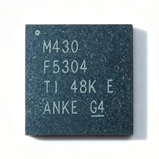
TMS320F28027FPTT - 60MHz C2000 MCU 64KB Flash | Texas Instruments
Référence : F28027FPTT ✓ Actif| Qté | Prix unitaire | Total |
|---|---|---|
| 1 | $2.55 | $2,55 |
| 10 | $2.3 | $23,00 |
| 100 | $2.05 | $205,00 |
| 500 | $1.85 | $925,00 |
| 1 000 | $1.65 | $1 650,00 |
F28027FPTT Présentation
A microcontroller (MCU) is a compact integrated circuit designed to govern a specific operation in an embedded system. It contains a processor core, memory, and programmable input/output peripherals. The C2000 family is a specialized line of MCUs optimized for real-time control, combining the C28x DSP core with control peripherals like PWM, ADC, and quadrature encoder interfaces. This makes them ideal for motor control, digital power conversion, and industrial automation.
Key features of the TMS320F28027FPTT include a 60 MHz C28x CPU, 64 KB flash, 12-bit ADC with up to 16 channels, multiple PWM modules, and a variety of communication interfaces such as SPI, SCI (UART), and I2C. The device operates from a single 3.3V supply thanks to an internal voltage regulator, simplifying power design. It also includes a hardware floating-point unit (FPU) for faster math operations.
Technically, the C28x core is a 32-bit fixed-point architecture with a Harvard bus structure, enabling simultaneous instruction and data fetches. The device supports up to 60 MHz operation with a 3.3V supply, and includes a 128-bit security key to protect proprietary code. The integrated analog-to-digital converter (ADC) offers 12-bit resolution with a conversion time of 216 ns, suitable for high-speed control loops.
Typical applications include motor control for appliances and industrial drives, digital power supplies, solar inverters, and automotive systems. The device's high-performance PWM and ADC make it ideal for closed-loop control algorithms. Its low pin count and integrated peripherals reduce system cost and board space.
When designing with this MCU, ensure proper decoupling of the 3.3V supply and use the internal voltage regulator's output for the core. The device supports JTAG debugging and programming, and the InstaSPIN-FOC library is available for sensorless motor control. Careful layout of the analog and digital grounds is recommended for optimal ADC performance.
Alternatives de remplacement direct pour F28027FPTT — même boîtier, compatible broche à broche. Les références à boîtier différent nécessitant une retouche du PCB sont exclues.
Variantes de cette série
Modèles de la même série directement compatibles avec F28027FPTT (même facteur de forme et même empreinte) — différant par Supply Voltage, Code Compatibility, Core, Flash Memory, SRAM.
Outil de comparaison rapide — sélectionnez des références alternatives pour une comparaison côte à côte :
TMS320F28027PTT
✅ Remplacement direct✓ En stock
$2.68 / unité
Voir la fiche technique →TMS320F28026FPTT
✅ Remplacement direct ⚠️ Spécifications non vérifiées📋 Alternative de référence (hors catalogue)
TMS320F28023FPTT
✅ Remplacement direct ⚠️ Spécifications non vérifiées📋 Alternative de référence (hors catalogue)
TMS320F28027FPTQR
✅ Remplacement direct ⚠️ Spécifications non vérifiées📋 Alternative de référence (hors catalogue)
TMS320F28027FPTT
✅ Remplacement direct✓ En stock
$1 / unité
Voir la fiche technique →F28027FPTT Valeurs maximales et caractéristiques électriques
| Core | C28x (32-bit) |
| Fréquence d'horloge maximale | 60 MHz |
| Program Memory Size | 64 KB (32K x 16) |
| Largeur du bus de données | 32 bit |
| ADC Resolution | 12-bit |
| Communication Interfaces | SPI, SCI (UART), I2C |
| Tension d'alimentation | 3.3V (single rail) |
| Plage de température de fonctionnement | -40°C to +105°C |
| Boîtier | 48-LQFP (7x7 mm) |
| Type de montage | Surface Mount |
| Statut RoHS | Compliant |
| InstaSPIN-FOC | Yes (in ROM) |
Configuration des broches de F28027FPTT
| Broche 1 | VDDIO — I/O supply voltage (3.3V) |
| Broche 2 | VSS — Ground |
| Broche 3 | GPIO0 — General purpose I/O / PWM |
| Broche 4 | GPIO1 — General purpose I/O / PWM |
| Broche 5 | GPIO2 — General purpose I/O / PWM |
| Broche 6 | GPIO3 — General purpose I/O / PWM |
| Broche 7 | GPIO4 — General purpose I/O / PWM |
| Broche 8 | GPIO5 — General purpose I/O / PWM |
| Broche 9 | GPIO6 — General purpose I/O / PWM |
| Broche 10 | GPIO7 — General purpose I/O / PWM |
| Broche 11 | VDD — Core supply (1.8V internal) |
| Broche 12 | VSS — Ground |
| Broche 13 | GPIO8 — General purpose I/O / PWM |
| Broche 14 | GPIO9 — General purpose I/O / PWM |
| Broche 15 | GPIO10 — General purpose I/O / PWM |
| Broche 16 | GPIO11 — General purpose I/O / PWM |
| Broche 17 | GPIO12 — General purpose I/O / PWM |
| Broche 18 | GPIO13 — General purpose I/O / PWM |
| Broche 19 | GPIO14 — General purpose I/O / PWM |
| Broche 20 | GPIO15 — General purpose I/O / PWM |
| Broche 21 | VDDIO — I/O supply voltage (3.3V) |
| Broche 22 | VSS — Ground |
| Broche 23 | GPIO16 — General purpose I/O / PWM |
| Broche 24 | GPIO17 — General purpose I/O / PWM |
| Broche 25 | GPIO18 — General purpose I/O / PWM |
| Broche 26 | GPIO19 — General purpose I/O / PWM |
| Broche 27 | GPIO20 — General purpose I/O / PWM |
| Broche 28 | GPIO21 — General purpose I/O / PWM |
| Broche 29 | GPIO22 — General purpose I/O / PWM |
| Broche 30 | GPIO23 — General purpose I/O / PWM |
| Broche 31 | VDD — Core supply (1.8V internal) |
| Broche 32 | VSS — Ground |
| Broche 33 | GPIO24 — General purpose I/O / PWM |
| Broche 34 | GPIO25 — General purpose I/O / PWM |
| Broche 35 | GPIO26 — General purpose I/O / PWM |
| Broche 36 | GPIO27 — General purpose I/O / PWM |
| Broche 37 | GPIO28 — General purpose I/O / PWM |
| Broche 38 | GPIO29 — General purpose I/O / PWM |
| Broche 39 | GPIO30 — General purpose I/O / PWM |
| Broche 40 | GPIO31 — General purpose I/O / PWM |
| Broche 41 | VDDIO — I/O supply voltage (3.3V) |
| Broche 42 | VSS — Ground |
| Broche 43 | XCLKIN — External clock input |
| Broche 44 | X1 — Crystal oscillator input |
| Broche 45 | X2 — Crystal oscillator output |
| Broche 46 | VDD — Core supply (1.8V internal) |
| Broche 47 | VSS — Ground |
| Broche 48 | TRST — JTAG test reset |
Applications typiques
F28027FPTT convient pour 6 applications: Motor Control, Digital Power Conversion, Solar Inverters, Industrial Automation, Automotive Systems, Home Appliances.
Motor Control
The TMS320F28027FPTT is ideal for motor control applications such as variable speed drives, pumps, and fans. Its 60 MHz C28x core with FPU enables high-speed FOC algorithms, and the integrated PWM and ADC provide precise control. The InstaSPIN-FOC library simplifies sensorless control, reducing development time. With 12-bit ADC and multiple PWM channels, it can handle complex control loops with minimal external components.
Recommandé
Digital Power Conversion
The TMS320F28027FPTT excels in digital power supplies, including AC-DC and DC-DC converters. Its high-speed ADC and PWM modules enable digital control loops with high bandwidth. The 60 MHz core can execute complex algorithms like PID and predictive control. The device's integrated analog comparators and trip zones enhance protection. This makes it suitable for server power supplies, telecom rectifiers, and solar inverters.
Recommandé
Solar Inverters
In solar inverters, the TMS320F28027FPTT manages MPPT (Maximum Power Point Tracking) and grid-tie control. Its 12-bit ADC samples voltage and current from solar panels, while PWM generates switching signals for the inverter bridge. The C28x core's math capabilities handle complex algorithms like perturb-and-observe MPPT. The device's robust peripherals ensure reliable operation in harsh environments.
Recommandé
Industrial Automation
The TMS320F28027FPTT is used in industrial automation for PLCs, robotics, and process control. Its multiple communication interfaces (SPI, SCI, I2C) allow easy integration with sensors and actuators. The device's real-time control capabilities enable precise motion control and monitoring. The 48-pin LQFP package is compact, suitable for space-constrained industrial modules.
Recommandé
Automotive Systems
The TMS320F28027FPTT is suitable for automotive applications like engine control, transmission control, and electric power steering. Its high-temperature rating (-40°C to +105°C) and robust peripherals meet automotive requirements. The device's PWM and ADC are used for sensor feedback and actuator control. While not AEC-Q100 qualified, it is often used in non-safety-critical automotive modules.
Recommandé
Home Appliances
The TMS320F28027FPTT is used in home appliances such as washing machines, refrigerators, and air conditioners for motor control and user interface. Its low cost and integrated peripherals reduce system complexity. The device's energy-efficient operation helps meet energy standards. The InstaSPIN-FOC library enables quiet and efficient motor operation, improving appliance performance.
Recommandé
Récapitulatif des produits recommandés
Données de référence d'ingénierie pour F28027FPTT — comparaison, recommandations de conception et informations de conformité.
Guide de sélection
Comparaison avec les alternatives
| Paramètre | Ce produit | TMS320F28027PTT | TMS320F28026FPTT | TMS320F28023FPTT |
|---|---|---|---|---|
| Package | 48-LQFP (7x7 mm) | 48-LQFP (7x7 mm) | 48-LQFP (7x7 mm) | 48-LQFP (7x7 mm) |
| Brand | Texas Instruments | Texas Instruments | Texas Instruments | Texas Instruments |
| Core | C28x (32-bit) | C28x (32-bit) | C28x (32-bit) | C28x (32-bit) |
| Max Clock Frequency | 60 MHz | 60 MHz | 60 MHz | 60 MHz |
| Flash Memory | 64 KB | 64 KB | 32 KB | 32 KB |
| InstaSPIN-FOC | Yes | No | Yes | Yes |
| ADC Resolution | 12-bit | 12-bit | 12-bit | 12-bit |
| Supply Voltage | 3.3V | 3.3V | 3.3V | 3.3V |
Principaux différenciateurs
- Integrated InstaSPIN-FOC in ROM (vs TMS320F28027PTT)
- Higher flash memory (64 KB) (vs TMS320F28026FPTT)
- Pin-to-pin compatibility with non-'F' variant (vs TMS320F28027PTT)
Notes de conception
The TMS320F28027FPTT operates from a single 3.3V supply, with an internal voltage regulator generating the 1.8V core voltage. Ensure the 3.3V supply is clean and well-regulated, with a 10uF and 0.1uF decoupling capacitor placed close to the VDDIO pins. The internal regulator requires a 1.2uF capacitor on the VREG output pin for stability.
For optimal ADC performance, separate analog and digital ground planes and connect them at a single point. Place the ADC reference decoupling capacitors close to the ADC pins. Keep high-speed digital traces away from analog input traces to minimize noise coupling. Use a solid ground plane under the device.
Do not exceed the absolute maximum ratings for VDDIO (3.6V) or VDD (2.1V). Ensure the JTAG pins are properly terminated to avoid unintended programming issues. When using the internal oscillator, place the crystal and load capacitors close to the X1/X2 pins. Also, ensure the boot mode pins are set correctly for the desired boot source.
Informations de conformité
RoHS compliant per TI product page. Not AEC-Q100 qualified; for automotive use, consider TI's Q1 versions.