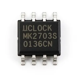
LM555CMX - 100kHz Single Timer | Texas Instruments | 8-SOIC
Référence : LM555CMX ✓ ActifLM555CMX Présentation
A 555 timer is a programmable timing integrated circuit that determines an output transition from the charging and discharging of an external timing capacitor. In the broader semiconductor hierarchy, the LM555 belongs to the timer and oscillator family, within clock and timing integrated circuits and power-management-adjacent signal-control devices. Its internal comparators and flip-flop allow an external resistor-capacitor network to establish delay, repetition rate, or pulse width without digital programming.
The LM555CMX supports three principal operating modes. In monostable operation, a trigger pulse creates one timed output pulse. In astable operation, the output oscillates continuously and can produce a duty cycle below 50% when the discharge path is used. In Schmitt-trigger operation, the internal thresholds generate a clean output transition from a slowly changing analog voltage. These functions make the timer useful for pulse generation, delay circuits, missing-pulse detection, tone generation, and simple power-control timing.
Its internal architecture is based on three comparators that monitor the timing-capacitor voltage, the trigger voltage, and the reset input. The flip-flop records comparator decisions, while separate bipolar output transistors provide a standard output and a higher-current discharge path. The 100 kHz operating limit establishes the upper end of the usable timing-frequency range, while the exact minimum and maximum timing values depend on the selected external resistance and capacitance.
Typical applications include industrial control timers, LED flashers, audio tone generators, delayed relay activation, pulse-width shaping, and oscillator-based clocking for small embedded systems. The SOIC-8 package supports compact surface-mount assembly while preserving the familiar eight-pin 555 interface. A timing capacitor and associated resistors remain external, allowing the circuit designer to select timing values rather than relying on a fixed internal delay.
The primary design consideration is preserving adequate timing-capacitor headroom for the trigger and threshold limits while keeping the discharge and control-node waveforms valid. Use the manufacturer's recommended resistor and capacitor ranges, account for component tolerances, and decouple the supply pin close to the device. Because this is a bipolar timer rather than a low-power CMOS timer, verify output-drive, supply-current, and timing requirements when operating from a constrained power source.
This page combines the LM555CMX timing characteristics and package information with practical mode-selection guidance, pin-assignment context, drop-in alternatives, and design notes intended to accelerate schematic review, PCB planning, sourcing, and legacy-maintenance work.
Alternatives de remplacement direct pour LM555CMX — même boîtier, compatible broche à broche. Les références à boîtier différent nécessitant une retouche du PCB sont exclues.
Variantes de cette série
Modèles de la même série directement compatibles avec LM555CMX (même facteur de forme et même empreinte) — différant par Package, Timer Type.
LM555CM
✅ Remplacement directContactez-nous pour le prix
Voir la fiche technique →LM555CMX
✅ Remplacement directContactez-nous pour le prix
Voir la fiche technique →LM555CMX
✅ Remplacement directContactez-nous pour le prix
Voir la fiche technique →TLC555IDR
✅ Remplacement direct📋 Alternative de référence (hors catalogue)
LMC555CM
✅ Remplacement direct📋 Alternative de référence (hors catalogue)
SE555D
✅ Remplacement direct📋 Alternative de référence (hors catalogue)
LM555CMX Spécifications
| Timer Type | 555 Type, single timer/oscillator |
| Maximum Timing Frequency | 100 kHz |
| Plage de température de fonctionnement | 0°C to 70°C |
| Boîtier | 8-SOIC |
| Nombre de broches | 8 pins |
| Type de montage | Surface mount |
| Timing Modes | Astable, monostable, and Schmitt trigger |
Configuration des broches de LM555CMX
| Broche 1 | GND — Ground reference |
| Broche 2 | TRIG — Trigger input; a low-going pulse initiates the timing cycle |
| Broche 3 | OUT — Timer output |
| Broche 4 | RESET — Reset input; a low level resets the timer |
| Broche 5 | CTRL — Control-voltage input for threshold adjustment |
| Broche 6 | DIS — Discharge output for the external timing capacitor |
| Broche 7 | THR — Threshold input that monitors the timing-capacitor voltage |
| Broche 8 | VCC — Positive supply connection |
Applications typiques
LM555CMX convient pour 7 applications: Industrial Delay and Relay Control, Astable LED Flashing, Audio Tone Generation, Pulse-Width Shaping and Conditioning, Long-Period Repetitive Timing, Clocked Oscillator for Control Systems, Threshold and Missing-Pulse Detection.
Industrial Delay and Relay Control
The LM555CMX fits delay and relay-control circuits because its monostable mode converts a trigger into a defined output interval. The device operates in the 0°C to 70°C range and is available in an 8-SOIC package, allowing a compact implementation beside a controller. Use the trigger and threshold inputs with the external timing network to establish the delay, then drive the relay through a suitable interface stage rather than exceeding the timer output-current limit. Component tolerances should be included when the relay must not operate outside its permitted timing window.
Recommandé
Astable LED Flashing
An LM555CMX configured as an astable oscillator can flash an LED at a repetition rate below its 100 kHz upper limit. The threshold and discharge pins charge and discharge the external capacitor, while the output supplies a timed drive signal. This configuration is useful in indicator, beacon, and low-speed visual-alarm circuits where a simple resistor-and-capacitor timing network is preferable to programmed timing. Select the resistor and capacitor within the datasheet limits, and add a transistor when the LED current exceeds the timer output capability.
Audio Tone Generation
The LM555CMX can generate an audible tone in astable mode by setting the timing network for the desired frequency and adding an output stage for speaker drive. Its 100 kHz maximum timing frequency provides ample margin for ordinary audio tones, while the output transistor supports a simple load interface. Use the control-node bypass capacitor to stabilize the timing circuit and keep the timing network away from noisy switching paths. A transistor or amplifier is necessary when the required speaker current exceeds the timer's output rating.
Pulse-Width Shaping and Conditioning
The LM555CMX is useful for shaping irregular pulses into a predictable monostable interval. A trigger initiates the timing cycle, and the internal flip-flop converts the capacitor-voltage decision into a clean digital output transition. The 8-SOIC package supports dense control boards, while the 0°C to 70°C commercial range covers many industrial and instrumentation environments. Validate pulse amplitude and polarity before applying the trigger, and use the reset input when immediate termination or fault shutdown is required.
Long-Period Repetitive Timing
For long or repetitive timing intervals, the LM555CMX can use a larger timing resistor and capacitor in monostable or astable configuration. The manufacturer describes the timer family as supporting timing from microseconds through hours. The device therefore suits maintenance timers, sampling intervals, and repeated test-cycle triggers without digital programming. Account for electrolytic-capacitor tolerance, leakage, temperature drift, and resistor tolerance because these practical characteristics can dominate long timing intervals even when the timer itself is operating correctly.
Clocked Oscillator for Control Systems
The LM555CMX can act as a clock source for small control or monitoring systems where a repeatable low-frequency square wave is sufficient. Its 100 kHz maximum frequency and eight-pin SOIC footprint support both astable and monostable timer arrangements. The output can synchronize sampling, trigger a counter, or periodically enable another circuit. Maintain short supply bypass connections and isolate the timing node from high-current switching paths to avoid period shifts. Confirm output rise and fall behavior in the intended logic system.
Recommandé
Threshold and Missing-Pulse Detection
Using the threshold, trigger, and output functions, an LM555CMX can support simple event-detection and missing-pulse logic in legacy equipment. The timing capacitor establishes a reference interval, and deviations from the expected input sequence produce a defined output state. This makes the timer suitable for supervisory circuits where complexity must remain low and repairability matters. Because the device is a bipolar 100 kHz timer in an 8-SOIC package, verify input thresholds against the original system logic and include supply filtering for long monitoring intervals.
Recommandé
Données de référence d'ingénierie pour LM555CMX — comparaison, recommandations de conception et informations de conformité.
Guide de sélection
Comparaison avec les alternatives
| Paramètre | Ce produit | LM555CM | LM555CMX | LM555CMX | TLC555IDR | LMC555CM |
|---|---|---|---|---|---|---|
| Brand | Texas Instruments | Texas Instruments | onsemi | Rochester Electronics | Texas Instruments | Texas Instruments |
| Package | 8-SOIC | 8-SOIC | 8-SOIC | 8-SOIC | SOIC-8 | 8-SOIC |
| Timer Type | 555 Type, single timer/oscillator | 555 Type, single timer/oscillator | 555 Type, single timer/oscillator | 555 Type, single timer/oscillator | Single CMOS timer/oscillator | Single CMOS timer/oscillator |
| Number of Pins | 8 pins | 8 pins | 8 pins | 8 pins | 8 pins | 8 pins |
Principaux différenciateurs
- Direct 100 kHz bipolar 555 positioning (vs TLC555IDR)
- Eight-pin package compatibility (vs LMC555CM)
- Commercial-temperature timer in a compact surface-mount package (vs LM555CM)
Notes de conception
Place the timing capacitor and its associated resistors close to the threshold, trigger, and discharge pins to minimize parasitic capacitance and resistive interference. The 8-SOIC footprint provides easy access to all eight functions, but long timing-node traces can act as additional capacitance and alter the calculated interval. Keep the control-node bypass capacitor close to its pin and route it away from output and discharge switching nodes.
Decouple the supply pin locally and provide a low-impedance ground return for output and discharge current. Although the LM555CMX is specified for a 100 kHz maximum frequency, the switching transitions at the discharge and output stages can create transient supply current even at low repetition rates. Place the manufacturer-recommended bypass capacitor adjacent to the IC and avoid sharing a narrow supply trace with relays, motors, or other high-current loads.
Do not assume that every 8-pin 555-family device is an equivalent substitute. TLC555IDR and LMC555-family parts use CMOS characteristics, including different input impedance, supply current, output behavior, and timing tolerances. For an existing LM555CMX design, compare the supply range, trigger and threshold levels, output source and sink current, maximum frequency, reset behavior, and timing equations before approving a replacement.
Include timing-component tolerances, temperature drift, leakage, and capacitor type in the interval-error budget. This is particularly important for long delays and precision monostable pulses, where electrolytic or film-capacitor variation can dominate the nominal calculation. For astable operation, verify both frequency and duty cycle because the conventional discharge-diode topology can modify the ratio from the ideal 50% result.
Informations de conformité
No specific RoHS, REACH, lead-free, halogen-free, or conflict-minerals statement was identified for this exact ordering option. The operating temperature of 0°C to 70°C indicates a commercial-temperature grade rather than an AEC-Q100 automotive qualification.