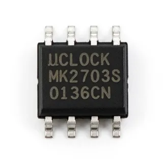
MC1455BD - 5V Programmable Timer/Oscillator | onsemi
Référence : MC1455BD ✓ ActifMC1455BD Présentation
A 555 timer is a type of programmable timer and oscillator within the broader clock and timing IC hierarchy. Its internal comparators, flip-flop, and discharge transistor allow a simple external RC network to determine delay time or oscillation frequency. Compared with a mechanical or discrete timing arrangement, the MC1455BD provides a compact and repeatable implementation for pulse generation, delay, flashing, and periodic control functions.
Key features include support for both monostable and astable operating modes, externally adjustable timing through one resistor and one capacitor in monostable operation, and separate trigger and reset terminals. The verified distributor information identifies the device as a 5 V, 555 Type, Timer/Oscillator (Single) IC in an 8-SOIC package. The onsemi datasheet also describes additional terminals for triggering or resetting when required.
The MC1455 architecture provides two useful operating behaviors. In monostable mode, a trigger pulse causes the output to enter a defined high state for a duration set primarily by the external timing resistor and capacitor. In astable mode, the output repeatedly switches between high and low states, with the external resistor-capacitor network setting the operating frequency and duty cycle. This makes one device suitable for both one-shot event timing and continuous pulse generation.
Typical applications include industrial control timers, LED flashers, pulse generators, delay circuits, repetitive switching circuits, and general-purpose timing modules. Its 8-pin SOIC package supports compact surface-mount PCB layouts, while the external RC components allow timing values to be selected for the particular load and system requirements. The device is also useful as the timing element in educational and prototype circuits where both monostable and astable configurations may be exercised.
Designers should select resistor and capacitor values that keep the timing network within the operating limits stated by the manufacturer datasheet and should account for component tolerance when precise timing is required. The trigger and reset pins must be driven only to valid logic levels, and unused or unused-at-a-time inputs should be handled according to the datasheet rather than left floating. PCB layout should keep timing-node connections short and provide an adequate ground return.
This page combines verified manufacturer and distributor information, package and pin references, commercial availability, and qualified drop-in alternatives. It also provides application guidance and parameter-level comparison information intended to make timer selection and PCB reuse easier than a raw datasheet summary alone.
Alternatives de remplacement direct pour MC1455BD — même boîtier, compatible broche à broche. Les références à boîtier différent nécessitant une retouche du PCB sont exclues.
ICM7555CBAZ
✅ Remplacement direct📋 Alternative de référence (hors catalogue)
MC1455BD Spécifications
| Product Type | 555 Type Timer/Oscillator (Single) |
| Tension d'alimentation | 5 V |
| Operating Modes | Monostable and astable |
| Timing Control | One external resistor and one external capacitor in time-delay mode |
| Oscillator Frequency Control | Externally controlled by resistor-capacitor network |
| Trigger Input | Available |
| Reset Input | Available |
| Output | Single timer output |
| Boîtier | 8-SOIC |
| Nombre de broches | 8 pins |
| Type de montage | Surface mount |
| Technology | Monolithic timing circuit |
Configuration des broches de MC1455BD
| Broche 1 | GND — Ground reference |
| Broche 2 | TRIG — Trigger input |
| Broche 3 | OUT — Timer output |
| Broche 4 | RESET — Reset input |
| Broche 5 | VCC — Positive supply input |
| Broche 6 | DIS — Discharge terminal for the external timing network |
| Broche 7 | THRES — Threshold input |
| Broche 8 | NC — Not connected |
Applications typiques
MC1455BD convient pour 6 applications: LED Flasher and Warning Circuit, Monostable One-Shot Delay, Industrial Pulse and Relay Driver, Audio Tone and Audible Alert Generator, Automated Test Fixture Trigger, General-Purpose Timing Module.
LED Flasher and Warning Circuit
The MC1455BD fits an LED flasher because the onsemi datasheet confirms astable operation, in which the output repeatedly changes state and drives the external timing network. The MC1455BD operates at 5 V, matching the supply level identified in the verified distributor listing, while its 8-SOIC package supports compact surface-mount construction. A series resistor limits LED current, while the resistor-capacitor network establishes the flash rate and duty cycle. The timing nodes should remain short to reduce noise pickup, and the LED current should be checked against both the LED rating and the MC1455BD output limits before layout release.
Recommandé
Monostable One-Shot Delay
The MC1455BD is appropriate for a one-shot delay because its trigger terminal can initiate a timed output pulse and its reset terminal provides additional control. According to the onsemi datasheet, time-delay operation is controlled by one external resistor and one capacitor, allowing the pulse duration to be scaled to the system requirement. This architecture is useful for actuator triggering, sampling windows, and event qualification. Because the verified results do not provide the complete timing tolerance or trigger-threshold tables, engineers must use the manufacturer datasheet to establish logic levels and tolerance limits before qualification.
Recommandé
Industrial Pulse and Relay Driver
The MC1455BD can generate repeatable control pulses for industrial sequencing, test fixtures, and relay-driver logic. Its verified 5 V operation and 8-SOIC package allow it to be placed close to the controlled circuitry, reducing trace length on timing-sensitive nodes. The output can initiate a downstream driver stage rather than directly driving a high-current relay unless its output limits are verified. Trigger and reset inputs provide deterministic start and abort behavior, while the external timing network should be selected with tolerance and temperature considerations appropriate to the required timing accuracy.
Recommandé
Audio Tone and Audible Alert Generator
The MC1455BD can support a simple audible alert or tone generator when operated as an astable oscillator and connected to an appropriate sound-producing load. The onsemi documentation confirms that free-running frequency and duty-cycle behavior can be established with external timing components, making the device suitable for repetitive audible patterns. A 5 V-compatible drive stage or speaker interface should be selected according to the verified output-current requirements. Keep the oscillator loop compact, provide low-impedance decoupling, and avoid directly overloading the timer output with an unverified loudspeaker connection.
Recommandé
Automated Test Fixture Trigger
The MC1455BD is useful in automated test fixtures as a triggerable pulse source for sequencing measurements, relay contacts, or acquisition equipment. Its monostable behavior provides a defined output interval after an external trigger, while the reset input permits the sequence to be aborted. The 8-SOIC package reduces board area compared with larger through-hole timer packages and can simplify assembly. For measurement accuracy, verify the trigger thresholds and output rise or fall behavior from the onsemi datasheet, and avoid introducing long traces between the timing capacitor, threshold node, and trigger node.
Recommandé
General-Purpose Timing Module
The MC1455BD works as a general-purpose timing module in prototypes, educational circuits, and control boards that need either one-shot or repetitive behavior from the same device. Its verified 8-SOIC package is compatible with standard surface-mount assembly, and the onsemi datasheet confirms externally adjustable timing through resistors and capacitors. Designers can select component values to establish the required interval and use the trigger and reset inputs for external coordination. Before committing to production, check supply-current, output-drive, timing-tolerance, and temperature specifications in the manufacturer datasheet because those values were not included in the supplied search snippets.
Recommandé
Données de référence d'ingénierie pour MC1455BD — comparaison, recommandations de conception et informations de conformité.
Guide de sélection
Comparaison avec les alternatives
| Paramètre | Ce produit | ICM7555CBAZ |
|---|---|---|
| Brand | onsemi | Renesas Electronics |
| Package | 8-SOIC | 8-SOIC |
| Product Type | 555 Type Timer/Oscillator (Single) | 555 Type Timer/Oscillator (Single) |
| Operating Modes | Monostable and astable | Monostable and astable |
| Pin Count | 8 pins | 8 pins |
| Mounting Type | Surface mount | Surface mount |
Principaux différenciateurs
- Verified onsemi 5 V timer sourcing (vs ICM7555CBAZ)
- Direct manufacturer family support (vs ICM7555CBAZ)
- Single timer footprint with external timing control (vs ICM7555CBAZ)
Notes de conception
Do not substitute a generic 555 solely because its output function appears equivalent. Confirm the SOIC-8 package dimensions, pin orientation, trigger and reset thresholds, output-current capability, discharge-transistor limits, supply-voltage range, and timing limits. The supplied cross-reference results identify comparable timer devices, but they do not provide a complete electrical-equivalence table, so a schematic-compatible footprint alone does not establish production equivalence.
Keep the timing capacitor, threshold pin, trigger pin, and discharge path compact to reduce parasitic capacitance and noise pickup. Place the timing components near pins 2, 6, and 7, route the discharge output directly to the timing resistor, and avoid sharing long sensitive timing traces with switching nodes. Provide a low-impedance ground plane connection and decouple the 5 V supply near the device according to the manufacturer datasheet.
The discharge output must sink the current associated with the external timing capacitor and resistor, while the output pin must remain within its verified voltage and current limits. Confirm output-drive capability before driving a logic gate, relay driver, lamp, or other load directly. If the load current is uncertain, use an external transistor or driver stage and preserve the MC1455BD's timing function with an appropriate interface circuit.
Informations de conformité
The supplied manufacturer and distributor snippets do not explicitly state RoHS, REACH, lead-free, halogen-free, or conflict-minerals status. AEC-Q100 is not applicable because MC1455BD is listed as a general-purpose timer rather than an automotive-qualified variant.