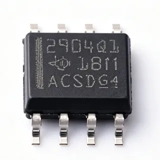
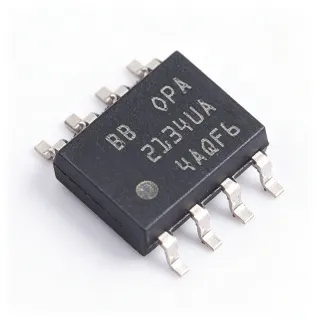
OPA2192IDR - 36V Precision RRIO Dual Op Amp e-Trim | TI
Référence : OPA2192IDR ✓ Actif| Qté | Prix unitaire | Total |
|---|---|---|
| 1 | $1.25 | $1,25 |
| 10 | $1.12 | $11,20 |
| 100 | $0.95 | $95,00 |
| 500 | $0.88 | $440,00 |
| 1 000 | $0.82 | $820,00 |
OPA2192IDR Présentation
A precision operational amplifier is a type of analog amplifier IC designed to amplify small differential signals with minimal error, positioned within the hierarchy of op amps > precision amplifiers > analog front-end ICs > linear ICs. Unlike general-purpose op amps, precision amplifiers minimize input offset voltage, bias current, and drift so sensor and measurement signal chains remain accurate without external trimming.
Key features include operation from 4.5V to 36V single supply (or +/-2.25V to +/-18V dual supply), a 10MHz gain-bandwidth product, and a 20V/us slew rate - a rare combination of DC precision and AC performance. The e-trim architecture achieves very low offset voltage without system-level trimming, while rail-to-rail inputs allow the common-mode range to extend to both supplies and rail-to-rail output maximizes dynamic range on low-voltage rails.
Architecturally, the OPA2192 uses an input stage that seamlessly transitions between two differential pairs to maintain rail-to-rail common-mode operation, with e-trim calibration performed at wafer test to null residual offset. The low input bias current suits high-impedance sources, and low total harmonic distortion supports precision AC signal chains.
Typical applications include industrial data acquisition front ends, transimpedance and sensor signal conditioning, precision active filters, and single-supply battery-powered instrumentation. The wide 36V supply rating also allows direct connection to industrial 24V rails with simple headroom management.
Design tip: reference the input common-mode near mid-supply to minimize crossover distortion inherent in dual-pair input stages, and verify AC behavior near the rails in high-precision designs.
Alternatives de remplacement direct pour OPA2192IDR — même boîtier, compatible broche à broche. Les références à boîtier différent nécessitant une retouche du PCB sont exclues.
Variantes de cette série
Modèles de la même série directement compatibles avec OPA2192IDR (même facteur de forme et même empreinte) — différant par Package, Input Bias Current, Input Offset Voltage, Input Voltage Noise Density, Slew Rate.
Outil de comparaison rapide — sélectionnez des références alternatives pour une comparaison côte à côte :
OPA2172IDR
✅ Remplacement direct📋 Alternative de référence (hors catalogue)
OPA2187IDR
✅ Remplacement direct ⚠️ Spécifications non vérifiées📋 Alternative de référence (hors catalogue)
OPA2171IDR
✅ Remplacement direct ⚠️ Spécifications non vérifiées📋 Alternative de référence (hors catalogue)
OPA2188IDR
✅ Remplacement direct ⚠️ Spécifications non vérifiées📋 Alternative de référence (hors catalogue)
LTC2051CMS8#PBF
✅ Remplacement direct📋 Alternative de référence (hors catalogue)
AD8659ARMZ
✅ Remplacement direct ⚠️ Spécifications non vérifiées📋 Alternative de référence (hors catalogue)
OPA2192IDR Valeurs maximales et caractéristiques électriques
| Number of Channels | 2 |
| Supply Voltage Range (Single) | 4.5 V to 36 V |
| Supply Voltage Range (Dual) | +/-2.25 V to +/-18 V |
| Gain-Bandwidth Product | 10 MHz |
| Slew Rate | 20 V/us |
| Input Offset Voltage | +/-25 uV (max) with e-trim |
| Input Bias Current | 5 pA (typical) |
| Input Voltage Noise Density | 8.8 nV/sqrt(Hz) at 1 kHz |
| Input/Output Type | Rail-to-Rail Input and Output (RRIO) |
| Courant de repos | 470 uA per amplifier |
| Température de fonctionnement | -40C to +125C |
| Boîtier | SOIC-8 (D) |
| Type de montage | Surface Mount |
| Niveau MSL | 2 (260C, 1 year) |
| Statut RoHS | Compliant |
| Output Current | 65 mA (per LCSC listed feature) |
Configuration des broches de OPA2192IDR
| Broche 1 | OUT A — Channel A output |
| Broche 2 | -IN A — Channel A inverting input |
| Broche 3 | +IN A — Channel A non-inverting input |
| Broche 4 | V- — Negative supply |
| Broche 5 | +IN B — Channel B non-inverting input |
| Broche 6 | -IN B — Channel B inverting input |
| Broche 7 | OUT B — Channel B output |
| Broche 8 | V+ — Positive supply |
Applications typiques
OPA2192IDR convient pour 6 applications: Industrial Data Acquisition Front End, Transimpedance Photodiode Amplifier, Sensor Signal Conditioning, Precision Active Filters, Battery-Powered Portable Instrumentation, Motor Control and Feedback Signal Chain.
Industrial Data Acquisition Front End
The OPA2192IDR fits industrial DAQ front ends because its 36V supply rating tolerates industrial rails while its +/-25uV max offset and 5pA bias current preserve measurement accuracy from millivolt-level sensors. Used as a buffer or gain stage ahead of an ADC such as the ADS131M08, it drives sampling inputs from its rail-to-rail output with low distortion. The 10MHz bandwidth settles quickly between multiplexed channels, so scan rates stay high without accuracy trade-offs.
Recommandé
Transimpedance Photodiode Amplifier
In photodiode TIA circuits, the OPA2192IDR 5pA typical bias current keeps dark-current error negligible even with megaohm feedback resistors, while 8.8 nV/sqrt(Hz) input noise limits output noise at the TIA output. The 10MHz gain-bandwidth supports feedback resistors in the hundreds of kiloohms to megaohm range while retaining useful signal bandwidth, and the rail-to-rail input allows operation very close to ground in single-supply optical sensing modules.
Recommandé
Sensor Signal Conditioning
Bridge and low-impedance sensors such as pressure and load cells benefit from the OPA2192IDR low offset and e-trim calibration, which remove the need for costly system-level trimming. Configured as a two-amp or three-amp instrumentation topology, its 10MHz bandwidth and 20V/us slew rate support dynamic load measurements, while RRIO operation maximizes output swing on 5V or 24V supplies. Gain-setting resistors with 0.1% tolerance preserve the amplifier intrinsic precision.
Recommandé
Precision Active Filters
The OPA2192IDR 10MHz gain-bandwidth gives a factor of more than 100 over filter corner frequencies up to about 100kHz, holding filter Q and corner accuracy close to the passive-component-determined values. Its low offset keeps DC bias points in Sallen-Key and multiple-feedback topologies centered, and RRIO output allows large swings on single supplies. This makes it well suited to anti-aliasing filters in industrial and test equipment analog front ends.
Recommandé
Battery-Powered Portable Instrumentation
At 470uA per amplifier quiescent current, the dual-channel OPA2192IDR balances precision against battery budget in portable instruments. Rail-to-rail input and output maximize usable signal range as the supply sags, and operation down to 4.5V supports multi-cell lithium or alkaline packs. The low bias current allows high-impedance electrodes and sensors to be read directly, and the -40C to +125C rating covers outdoor and field-use environments.
Recommandé
Motor Control and Feedback Signal Chain
In 24V industrial drive systems, the OPA2192IDR conditions position, current, and back-EMF feedback signals directly from high-voltage rails without extra level shifting. Its 20V/us slew rate tracks fast PWM-referred signals, and the 36V rating gives headroom above nominal 24V supplies. Paired with TI C2000 ADC inputs, its rail-to-rail output uses the full converter range, improving effective resolution of the control loop.
Recommandé
Récapitulatif des produits recommandés
Données de référence d'ingénierie pour OPA2192IDR — comparaison, recommandations de conception et informations de conformité.
Guide de sélection
Comparaison avec les alternatives
| Paramètre | Ce produit | OPA2172IDR | OPA2187IDR | LTC2051CMS8#PBF |
|---|---|---|---|---|
| Package | SOIC-8 (D) | SOIC-8 (D) - same | SOIC-8 (D) - same | SOIC-8 - same |
| Brand | Texas Instruments | Texas Instruments | Texas Instruments | Analog Devices |
| Channels | 2 | 2 | 2 | 2 |
| Max Offset Voltage | +/-25 uV (e-trim) | 100 uV (typ) | 5 uV (zero-drift) | 1 uV (zero-drift) |
| Supply Range | 4.5 V to 36 V | 4.5 V to 36 V | 4.5 V to 36 V | 2.7 V to 5.5 V |
| Architecture | e-trim precision | General purpose | Zero-drift | Zero-drift chopper |
Principaux différenciateurs
- Combines 10MHz bandwidth with precision offset (vs OPA2172IDR)
- Wide 36V supply with low noise (vs LTC2051CMS8#PBF)
- Broadband precision vs zero-drift chopping (vs OPA2187IDR)
Notes de conception
The rail-to-rail input uses two differential pairs that hand off near mid-supply, producing a small offset transition across the crossover region. In high-gain DC circuits, avoid input common-mode sweeps that cross this region, or characterize offset across the full common-mode range using the curves in the TI datasheet before committing to a design.
Place 100nF ceramic decoupling capacitors within 2mm of pins 4 (V-) and 8 (V+), with a 10uF bulk capacitor per supply rail nearby. Keep feedback resistors close to the inverting inputs to minimize stray capacitance at summing nodes, which can erode phase margin, especially in transimpedance configurations with large feedback resistors.
In single-supply rail-to-rail output operation, output swing headroom varies with load current. For signals approaching the rails within 100mV, limit load to at least 10k ohm to preserve linearity. When driving capacitive loads directly (ADC inputs, cable), use an isolation resistor of 10-50 ohm or an RC network to maintain stability.
Informations de conformité
RoHS and REACH compliant per PartGenie compliance notes and TI product data. MSL level 2 (260C, 1 year).