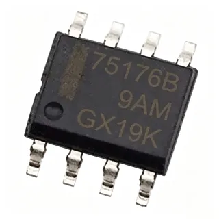
SP720ABTG - 14-Input 30V ESD TVS Array | Littelfuse
Référence : SP720ABTG ✓ Actif| Qté | Prix unitaire | Total |
|---|---|---|
| 1 | $1.2947 | $1,29 |
| 10 | $1.2947 | $12,95 |
| 100 | $1.2947 | $129,47 |
| 500 | $1.2947 | $647,35 |
| 1 000 | $1.2947 | $1 294,70 |
SP720ABTG Présentation
A TVS diode array is a circuit-protection device that diverts transient current to a supply or ground rail while limiting voltage at a sensitive interface. The SP720 belongs to the transient-voltage-suppressor, mixed-technology, ESD-protection, and circuit-protection hierarchy. It is intended for systems in which exposed conductors or connectors can receive electrostatic discharge before reaching a protected logic, data, control, or communication circuit.
The verified product data identifies 14 protection circuits in a surface-mount 16-SOIC package. Its 3 pF capacitance is particularly relevant to high-speed interfaces because parasitic capacitance can reduce signal rise time and disturb data timing. The 30 V and 1 A values characterize the protection device for design selection, but engineers should verify the complete datasheet limits, pulse conditions, and application configuration before relying on any rating.
The SP720 architecture uses fast SCR structures together with diode protection paths. Littelfuse positions this family for general-purpose logic protection, data-bus protection, industrial process equipment, and systems requiring transient protection across many external lines. The array consolidates fourteen protected inputs into one package, reducing the number of discrete protection devices required when many connector pins need common ESD handling.
Typical applications include industrial control interfaces, communication ports, instrumentation, data acquisition, embedded systems, and general-purpose connector protection. Protection is most effective when the protected traces are routed close to the connector, the array is connected to the appropriate supply or ground reference, and the signal integrity budget accounts for the array's capacitance. The part should not be treated as a substitute for surge-protection coordination outside the transient conditions covered by its manufacturer documentation.
Designers should compare capacitance, protected-line count, voltage limits, current ratings, package dimensions, and exact pin mapping against the protected interface. For a data bus, the 3 pF capacitance must be checked against edge rate and receiver timing. For industrial equipment, the manufacturer’s IEC electromagnetic-compatibility guidance should be reviewed, while the exact applicable standard, system test level, and installation conditions remain design-specific and are not established by the supplied snippets.
This page consolidates the verified manufacturer and distributor information, distinguishes the 14-input protection architecture from generic discrete TVS diodes, and provides practical selection and placement guidance. It does not infer unprovided production tolerances, temperature grades, surge endurance, or cross-manufacturer pin compatibility.
Alternatives de remplacement direct pour SP720ABTG — même boîtier, compatible broche à broche. Les références à boîtier différent nécessitant une retouche du PCB sont exclues.
Variantes de cette série
Modèles de la même série directement compatibles avec SP720ABTG (même facteur de forme et même empreinte).
Outil de comparaison rapide — sélectionnez des références alternatives pour une comparaison côte à côte :
SP720ABG
✅ Remplacement direct📋 Alternative de référence (hors catalogue)
SP720AB
✅ Remplacement direct📋 Alternative de référence (hors catalogue)
SP720ABT
✅ Remplacement direct📋 Alternative de référence (hors catalogue)
SP720AP
✅ Remplacement direct📋 Alternative de référence (hors catalogue)
SP720ABTG
✅ Remplacement direct✓ En stock
$1.2947 / unité
Voir la fiche technique →SP720ABTG Spécifications
| Product Type | TVS diode array |
| Protection Topology | Mixed-technology SCR/diode bipolar structures |
| Number of Protected Inputs | 14 inputs |
| Rated Voltage | 30 V |
| Rated Current | 1 A |
| Capacitance | 3 pF |
| Protection Reference Pin | Pin 8, V+ or V- |
| Protected Input Pins | Pins 1-7 and 9-15 |
| Device Classification | Mixed technology |
| Circuit Count | 14 circuits |
| Boîtier | 16-SOIC |
| Type de montage | Surface mount |
| Protection Function | ESD and over-voltage protection |
| Applications | General logic protection and data-bus protection |
| Manufacturer Series | SP720 Lead-Free/Green Series |
Configuration des broches de SP720ABTG
| Broche 1 | IN — Protected input 1 |
| Broche 2 | IN — Protected input 2 |
| Broche 3 | IN — Protected input 3 |
| Broche 4 | IN — Protected input 4 |
| Broche 5 | IN — Protected input 5 |
| Broche 6 | IN — Protected input 6 |
| Broche 7 | IN — Protected input 7 |
| Broche 8 | V+ or V- — Protection reference or supply connection |
| Broche 9 | IN — Protected input 9 |
| Broche 10 | IN — Protected input 10 |
| Broche 11 | IN — Protected input 11 |
| Broche 12 | IN — Protected input 12 |
| Broche 13 | IN — Protected input 13 |
| Broche 14 | IN — Protected input 14 |
| Broche 15 | IN — Protected input 15 |
| Broche 16 | [DATA_NEEDED: pin 16 name] — [DATA_NEEDED: pin 16 function and connection] |
Applications typiques
SP720ABTG convient pour 6 applications: Industrial Control Interfaces, Data-Bus Protection, General Logic Protection, Embedded System Connectors, Instrumentation and Data Acquisition, Communication Port Protection.
Industrial Control Interfaces
The SP720ABTG fits exposed industrial control, instrumentation, and process-measurement interfaces that can receive ESD transients through field wiring. Its 14 protected inputs allow one array to cover many connector conductors, while the 3 pF capacitance helps limit loading on moderate-speed control signals. Place the device near the connector entry, connect pin 8 to the applicable protection reference, and verify the manufacturer’s transient and EMC guidance for the final enclosure and cable environment.
Recommandé
Data-Bus Protection
The Littelfuse SP720ABTG can protect up to 14 external signal or bus lines from ESD and over-voltage events. Its 3 pF capacitance should be checked against bus edge rate, line length, receiver loading, and timing margin before placement. Route protected lines from the connector through the array’s input pins and keep the pin 8 V+ or V- reference connection short and low-impedance to provide a nearby transient-current path.
Recommandé
General Logic Protection
The SP720ABTG is appropriate for sensitive logic inputs that reach a board edge through wires, connectors, or user-accessible controls. Fourteen protected lines in a 16-SOIC package reduce the component count compared with a comparable collection of discrete protection devices. The protection device must be placed close to the entry point, with the protected logic and sensitive traces kept behind the array so that the transient is diverted before it reaches the receiver.
Recommandé
Embedded System Connectors
The 14-input SP720ABTG array can protect multiple connector pins on an embedded controller or data-acquisition board without requiring a separate protector for every line. The 30 V and 1 A values provide an initial protection-class selection point, while the 3 pF capacitance is the key signal-integrity check. Designers should maintain a short, direct path to the protection reference and confirm that the selected footprint and pin numbering match the exact Littelfuse package drawing.
Recommandé
Instrumentation and Data Acquisition
The SP720ABTG can protect external measurement and acquisition lines exposed to operator contact, short cables, or industrial transients. Its multi-line array architecture makes it suitable when a connector carries several related signals and the design needs common protection placement. Check the 3 pF capacitance against source impedance, sampling rate, analog bandwidth, and settling time; protection that is electrically safe can still degrade measurement accuracy if it adds excessive loading.
Recommandé
Communication Port Protection
The SP720ABTG is suitable for communication ports where multiple conductors enter through an exposed connector and transient suppression must be centralized near that entry. The manufacturer describes protection from the input pins to V+ or V-, and the array provides a 3 pF capacitance that may be suitable for many control or moderate-speed links. For high-speed protocols, perform a complete signal-integrity simulation or measurement because the supplied data does not provide a maximum data rate.
Recommandé
Récapitulatif des produits recommandés
Données de référence d'ingénierie pour SP720ABTG — comparaison, recommandations de conception et informations de conformité.
Guide de sélection
Comparaison avec les alternatives
| Paramètre | Ce produit | SP720ABG | SP720AB | SP720ABT | SP720AP |
|---|---|---|---|---|---|
| Brand | Littelfuse | Littelfuse | Littelfuse | Littelfuse | Littelfuse |
| Package | 16-SOIC | 16-SOIC | 16-SOIC | 16-SOIC | 16-SOIC |
| Application Category | General-purpose ESD and data-bus protection | Related SP720 series | Related SP720 series | Related SP720 series | Related SP720 series |
Principaux différenciateurs
- Fourteen protected external inputs in one array (vs SP720ABG)
- Mixed SCR/diode protection architecture (vs SP720AB)
- Documented pin-8 protection reference (vs SP720AP)
- Verified 3 pF capacitance for signal-integrity planning (vs SP720ABT)
Notes de conception
Place the SP720ABTG immediately adjacent to the connector or board entry point so the transient current is intercepted before it reaches protected logic. Route each exposed conductor through a designated IN pin, keep the connector-side traces short, and provide a low-impedance path from pin 8 to the selected V+ or V- reference. Do not rely on a distant array or a long unprotected stub to suppress an ESD event.
The verified 3 pF capacitance must be included in the input loading budget. For a digital interface, compare the added capacitance with the driver output impedance, receiver input capacitance, trace capacitance, target edge rate, and setup/hold timing. For an analog or acquisition node, check capacitive settling, source impedance, bandwidth, and measurement accuracy before placing the array beside the signal path.
Do not approve a related SP720AB, SP720ABG, SP720ABT, or SP720AP part as a drop-in substitute solely because the family name matches. Verify the complete datasheet pinout, protected-line count, reference connection, voltage and current ratings, capacitance, package dimensions, and pulse performance. Also verify the 16-SOIC land pattern and pin 1 orientation against the exact manufacturer drawing before fabrication.
The supplied search data does not provide the SP720ABTG transient power derating, operating temperature range, or pulse-duration curves. Consequently, no thermal calculation is supportable from the verified values. Review the complete Littelfuse datasheet for maximum pulse conditions, repetitive-event limits, and ambient-temperature derating, then ensure the PCB land and copper area match the manufacturer’s package guidance before production release.
Informations de conformité
The Littelfuse product family is identified as Lead-Free/Green, but the supplied verified excerpts do not explicitly establish the requested RoHS, REACH, halogen-free, or conflict-minerals statuses. AEC-Q100 is not applicable to this discrete protection device unless a specific automotive qualification is documented.