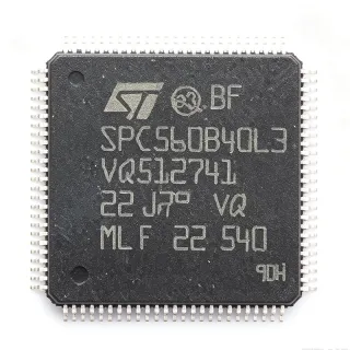
SPC560P40L3 - 32-bit MCU, 512KB Flash, 64MHz | STMicroelectronics
Référence : SPC560P40L3 ✓ Actif| Qté | Prix unitaire | Total |
|---|---|---|
| 1 | $12.5 | $12,50 |
| 10 | $11.25 | $112,50 |
| 100 | $10 | $1 000,00 |
| 500 | $9 | $4 500,00 |
| 1 000 | $8.1 | $8 100,00 |
SPC560P40L3 Présentation
A microcontroller (MCU) is a compact integrated circuit designed to govern a specific operation in an embedded system. It contains a processor core, memory (flash and RAM), and programmable input/output peripherals. The SPC560P40L3 belongs to the category of 32-bit automotive microcontrollers, which are optimized for real-time control, safety-critical functions, and harsh environments. These MCUs are part of the broader power management and control hierarchy, often used in engine control units (ECUs), body control modules, and industrial automation systems.
Key features of the SPC560P40L3 include a 64 MHz e200z0h core with single-precision floating-point unit (FPU), 512 KB flash with ECC, 48 KB SRAM, and a rich set of peripherals: 2x eSCI (UART), 2x DSPI (SPI), 1x FlexCAN, 1x eMIOS (timer), 1x ADC with 16 channels, and up to 64 GPIO pins. It supports a supply voltage range of 3.3V to 5V, with an operating temperature range of -40°C to +125°C, making it suitable for automotive under-hood applications. The device is AEC-Q100 qualified and RoHS compliant.
Technically, the SPC560P40L3 is built on a 90nm flash process, offering a balance of performance and power efficiency. The e200z0h core is a Power Architecture v1.1 compliant core with variable-length encoding (VLE) for code density, reducing memory footprint. The MCU includes a memory protection unit (MPU), a cyclic redundancy check (CRC) unit, and a fail-safe protection module, enhancing reliability for safety-critical systems. The FlexCAN module supports CAN 2.0B with up to 32 message buffers, enabling robust communication in automotive networks.
Typical applications include automotive body control modules (BCMs), engine management systems, transmission control units, and industrial motor control. The SPC560P40L3's combination of high-speed processing, extensive peripherals, and automotive-grade reliability makes it ideal for real-time control loops and communication-intensive tasks. For example, in a BCM, it manages lighting, door locks, and window lifts, while communicating over CAN bus.
When designing with this device, ensure proper decoupling of the power supply pins with 100nF capacitors close to each VDD pin, and a 10uF bulk capacitor. The device requires a stable clock source; an external 8-40 MHz crystal can be used with the on-chip oscillator. For safety-critical applications, use the built-in self-test (BIST) and CRC modules to meet ISO 26262 requirements. Also, consider the thermal dissipation: the LQFP-100 package has a thermal resistance of 45°C/W, so adequate PCB copper area is needed for high ambient temperatures.
Alternatives de remplacement direct pour SPC560P40L3 — même boîtier, compatible broche à broche. Les références à boîtier différent nécessitant une retouche du PCB sont exclues.
Outil de comparaison rapide — sélectionnez des références alternatives pour une comparaison côte à côte :
SPC560P40L3CEFAR
✅ Remplacement direct📋 Alternative de référence (hors catalogue)
SPC560P40L3CEAAY
✅ Remplacement direct📋 Alternative de référence (hors catalogue)
SPC560P40L3CEFA
✅ Remplacement direct📋 Alternative de référence (hors catalogue)
SPC560P40L1
✅ Remplacement direct ⚠️ Spécifications non vérifiées📋 Alternative de référence (hors catalogue)
SPC560P34L3
✅ Remplacement direct ⚠️ Spécifications non vérifiées📋 Alternative de référence (hors catalogue)
SPC560P40L3 Valeurs maximales et caractéristiques électriques
| Core | e200z0h (Power Architecture) |
| Maximum Frequency | 64 MHz |
| Flash Memory | 512 KB |
| RAM | 48 KB |
| Boîtier | LQFP-100 (14x14 mm) |
| Tension d'alimentation | 3.3V to 5V |
| Température de fonctionnement | -40°C to +125°C |
| AEC-Q100 | Qualified |
| RoHS | Compliant |
| ADC Channels | 16 |
| GPIO Pins | 64 |
| FlexCAN | 1 (CAN 2.0B, 32 message buffers) |
| eSCI (UART) | 2 |
| DSPI (SPI) | 2 |
| eMIOS (Timer) | 1 |
| Floating Point Unit | Single-precision |
| Process Technology | 90nm flash |
| Résistance thermique | 45°C/W |
Configuration des broches de SPC560P40L3
| Broche 1 | VDD — Digital power supply |
| Broche 2 | VSS — Digital ground |
| Broche 3 | P0[0] — GPIO / eSCI0_TX |
| Broche 4 | P0[1] — GPIO / eSCI0_RX |
| Broche 5 | P0[2] — GPIO / DSPI0_SCK |
| Broche 6 | P0[3] — GPIO / DSPI0_SIN |
| Broche 7 | P0[4] — GPIO / DSPI0_SOUT |
| Broche 8 | P0[5] — GPIO / DSPI0_CS0 |
| Broche 9 | VDD_HV — High-voltage power supply |
| Broche 10 | VSS_HV — High-voltage ground |
| Broche 11 | P1[0] — GPIO / ADC0_CH0 |
| Broche 12 | P1[1] — GPIO / ADC0_CH1 |
| Broche 13 | P1[2] — GPIO / ADC0_CH2 |
| Broche 14 | P1[3] — GPIO / ADC0_CH3 |
| Broche 15 | P1[4] — GPIO / ADC0_CH4 |
| Broche 16 | P1[5] — GPIO / ADC0_CH5 |
| Broche 17 | P1[6] — GPIO / ADC0_CH6 |
| Broche 18 | P1[7] — GPIO / ADC0_CH7 |
| Broche 19 | VDD — Digital power supply |
| Broche 20 | VSS — Digital ground |
| Broche 21 | P2[0] — GPIO / eMIOS0_CH0 |
| Broche 22 | P2[1] — GPIO / eMIOS0_CH1 |
| Broche 23 | P2[2] — GPIO / eMIOS0_CH2 |
| Broche 24 | P2[3] — GPIO / eMIOS0_CH3 |
| Broche 25 | P2[4] — GPIO / eMIOS0_CH4 |
| Broche 26 | P2[5] — GPIO / eMIOS0_CH5 |
| Broche 27 | P2[6] — GPIO / eMIOS0_CH6 |
| Broche 28 | P2[7] — GPIO / eMIOS0_CH7 |
| Broche 29 | VDD — Digital power supply |
| Broche 30 | VSS — Digital ground |
| Broche 31 | P3[0] — GPIO / FlexCAN0_TX |
| Broche 32 | P3[1] — GPIO / FlexCAN0_RX |
| Broche 33 | P3[2] — GPIO / eSCI1_TX |
| Broche 34 | P3[3] — GPIO / eSCI1_RX |
| Broche 35 | P3[4] — GPIO / DSPI1_SCK |
| Broche 36 | P3[5] — GPIO / DSPI1_SIN |
| Broche 37 | P3[6] — GPIO / DSPI1_SOUT |
| Broche 38 | P3[7] — GPIO / DSPI1_CS0 |
| Broche 39 | VDD_HV — High-voltage power supply |
| Broche 40 | VSS_HV — High-voltage ground |
| Broche 41 | P4[0] — GPIO / ADC0_CH8 |
| Broche 42 | P4[1] — GPIO / ADC0_CH9 |
| Broche 43 | P4[2] — GPIO / ADC0_CH10 |
| Broche 44 | P4[3] — GPIO / ADC0_CH11 |
| Broche 45 | P4[4] — GPIO / ADC0_CH12 |
| Broche 46 | P4[5] — GPIO / ADC0_CH13 |
| Broche 47 | P4[6] — GPIO / ADC0_CH14 |
| Broche 48 | P4[7] — GPIO / ADC0_CH15 |
| Broche 49 | VDD — Digital power supply |
| Broche 50 | VSS — Digital ground |
| Broche 51 | P5[0] — GPIO / JTAG_TMS |
| Broche 52 | P5[1] — GPIO / JTAG_TCK |
| Broche 53 | P5[2] — GPIO / JTAG_TDI |
| Broche 54 | P5[3] — GPIO / JTAG_TDO |
| Broche 55 | P5[4] — GPIO / RESET |
| Broche 56 | P5[5] — GPIO / EXTAL |
| Broche 57 | P5[6] — GPIO / XTAL |
| Broche 58 | P5[7] — GPIO / TEST |
| Broche 59 | VDD — Digital power supply |
| Broche 60 | VSS — Digital ground |
| Broche 61 | P6[0] — GPIO / eMIOS0_CH8 |
| Broche 62 | P6[1] — GPIO / eMIOS0_CH9 |
| Broche 63 | P6[2] — GPIO / eMIOS0_CH10 |
| Broche 64 | P6[3] — GPIO / eMIOS0_CH11 |
| Broche 65 | P6[4] — GPIO / eMIOS0_CH12 |
| Broche 66 | P6[5] — GPIO / eMIOS0_CH13 |
| Broche 67 | P6[6] — GPIO / eMIOS0_CH14 |
| Broche 68 | P6[7] — GPIO / eMIOS0_CH15 |
| Broche 69 | VDD_HV — High-voltage power supply |
| Broche 70 | VSS_HV — High-voltage ground |
| Broche 71 | P7[0] — GPIO / DSPI1_CS1 |
| Broche 72 | P7[1] — GPIO / DSPI1_CS2 |
| Broche 73 | P7[2] — GPIO / DSPI1_CS3 |
| Broche 74 | P7[3] — GPIO / eSCI0_CTS |
| Broche 75 | P7[4] — GPIO / eSCI0_RTS |
| Broche 76 | P7[5] — GPIO / eSCI1_CTS |
| Broche 77 | P7[6] — GPIO / eSCI1_RTS |
| Broche 78 | P7[7] — GPIO / FlexCAN0_STBY |
| Broche 79 | VDD — Digital power supply |
| Broche 80 | VSS — Digital ground |
| Broche 81 | P8[0] — GPIO / ADC0_CH16 |
| Broche 82 | P8[1] — GPIO / ADC0_CH17 |
| Broche 83 | P8[2] — GPIO / ADC0_CH18 |
| Broche 84 | P8[3] — GPIO / ADC0_CH19 |
| Broche 85 | P8[4] — GPIO / ADC0_CH20 |
| Broche 86 | P8[5] — GPIO / ADC0_CH21 |
| Broche 87 | P8[6] — GPIO / ADC0_CH22 |
| Broche 88 | P8[7] — GPIO / ADC0_CH23 |
| Broche 89 | VDD — Digital power supply |
| Broche 90 | VSS — Digital ground |
| Broche 91 | P9[0] — GPIO / eMIOS0_CH16 |
| Broche 92 | P9[1] — GPIO / eMIOS0_CH17 |
| Broche 93 | P9[2] — GPIO / eMIOS0_CH18 |
| Broche 94 | P9[3] — GPIO / eMIOS0_CH19 |
| Broche 95 | P9[4] — GPIO / eMIOS0_CH20 |
| Broche 96 | P9[5] — GPIO / eMIOS0_CH21 |
| Broche 97 | P9[6] — GPIO / eMIOS0_CH22 |
| Broche 98 | P9[7] — GPIO / eMIOS0_CH23 |
| Broche 99 | VDD — Digital power supply |
| Broche 100 | VSS — Digital ground |
Applications typiques
SPC560P40L3 convient pour 6 applications: Automotive Body Control Module, Engine Management System, Transmission Control Unit, Industrial Motor Control, Automotive Safety Systems, Industrial Automation.
Automotive Body Control Module
The SPC560P40L3 is ideal for body control modules (BCMs) due to its 64 MHz e200z0h core, 512 KB flash, and robust CAN communication. It manages lighting, door locks, window lifts, and other body functions. The FlexCAN module with 32 message buffers ensures reliable communication with other ECUs. Its AEC-Q100 qualification and -40°C to +125°C range make it suitable for under-hood and cabin environments. The 16-channel ADC allows monitoring of analog sensors, while the eMIOS timer handles PWM for motor control. With 64 GPIO pins, it can interface with numerous switches and actuators. The device's low power consumption and high reliability are critical for always-on BCM applications. Designers can use the built-in self-test (BIST) and CRC modules to meet ISO 26262 safety requirements. The LQFP-100 package with 45°C/W thermal resistance requires adequate PCB copper for heat dissipation in high-temperature environments.
Recommandé
Engine Management System
In engine management systems, the SPC560P40L3 provides real-time control of fuel injection, ignition timing, and emissions. Its 64 MHz core and single-precision FPU handle complex algorithms for engine control. The 16-channel ADC reads sensors like throttle position, temperature, and oxygen sensors. The eMIOS timer generates precise PWM signals for injectors and ignition coils. FlexCAN communicates with other ECUs in the vehicle network. The 512 KB flash stores calibration data and control algorithms. The device's AEC-Q100 qualification ensures reliability under extreme temperatures and vibration. The MPU and CRC modules enhance safety for critical functions. Designers must ensure proper decoupling and a stable clock source, as described in the datasheet. The LQFP-100 package is suitable for engine control unit PCBs, but thermal management is essential due to high ambient temperatures.
Recommandé
Transmission Control Unit
The SPC560P40L3 is well-suited for transmission control units (TCUs) that require precise control of solenoids and valves. Its 64 MHz core and eMIOS timer provide accurate PWM generation for hydraulic control. The FlexCAN module enables communication with the engine ECU and other modules. The 512 KB flash stores complex shift algorithms, and the 48 KB RAM handles real-time data. The device's operating temperature range of -40°C to +125°C is essential for transmission environments. The ADC monitors pressure and temperature sensors. The MPU and CRC modules support safety-critical functions. The LQFP-100 package is compact enough for TCU PCBs. Designers should follow the datasheet's recommendations for power supply decoupling and clock configuration. The device's AEC-Q100 qualification ensures long-term reliability in harsh conditions.
Recommandé
Industrial Motor Control
The SPC560P40L3 is used in industrial motor control applications such as variable frequency drives and servo controllers. Its 64 MHz core and FPU handle complex control algorithms like FOC (Field-Oriented Control). The eMIOS timer generates PWM signals for inverter stages. The 16-channel ADC samples motor currents and voltages. The DSPI interfaces with external encoders and sensors. The device's wide supply voltage range (3.3V to 5V) simplifies interface with industrial logic. The operating temperature range of -40°C to +125°C suits harsh industrial environments. The FlexCAN module enables communication in factory automation networks. The 512 KB flash stores control firmware, and the 48 KB RAM handles real-time data. The MPU and CRC modules enhance safety for machinery. The LQFP-100 package is suitable for industrial PCBs, but thermal management is critical for high-power applications.
Recommandé
Automotive Safety Systems
The SPC560P40L3 is designed for automotive safety systems such as airbag control units and electronic stability control. Its AEC-Q100 qualification and built-in self-test (BIST) features support ISO 26262 compliance. The 64 MHz core provides fast processing for safety algorithms. The FlexCAN module enables communication with sensors and other ECUs. The 512 KB flash stores safety-critical firmware, and the 48 KB RAM handles real-time data. The device's operating temperature range of -40°C to +125°C is essential for safety systems. The MPU and CRC modules enhance data integrity. The 16-channel ADC monitors crash sensors. The eMIOS timer generates precise timing for actuator control. The LQFP-100 package is suitable for safety system PCBs. Designers must follow strict design guidelines for safety-critical applications, including proper decoupling and clock redundancy.
Recommandé
Industrial Automation
The SPC560P40L3 is used in industrial automation for PLCs, robotics, and process control. Its 64 MHz core and FPU handle complex control algorithms. The FlexCAN module enables communication in industrial networks. The 16-channel ADC interfaces with sensors, and the eMIOS timer generates PWM for actuators. The device's wide supply voltage range (3.3V to 5V) simplifies integration with industrial logic. The operating temperature range of -40°C to +125°C suits harsh factory environments. The 512 KB flash stores control programs, and the 48 KB RAM handles real-time data. The MPU and CRC modules enhance reliability. The LQFP-100 package is suitable for industrial PCBs. Designers should ensure proper decoupling and a stable clock source. The device's AEC-Q100 qualification ensures long-term reliability in demanding applications.
Recommandé
Récapitulatif des produits recommandés
Données de référence d'ingénierie pour SPC560P40L3 — comparaison, recommandations de conception et informations de conformité.
Guide de sélection
Comparaison avec les alternatives
| Paramètre | Ce produit | SPC560P40L3CEFAR | SPC560P40L3CEAAY | SPC560P40L3CEFA | SPC560P40L1 | SPC560P34L3 |
|---|---|---|---|---|---|---|
| Package | LQFP-100 | LQFP-100 | LQFP-100 | LQFP-100 | LQFP-100 | LQFP-100 |
| Brand | STMicroelectronics | STMicroelectronics | STMicroelectronics | STMicroelectronics | STMicroelectronics | STMicroelectronics |
| Core | e200z0h | e200z0h | e200z0h | e200z0h | e200z0h | e200z0h |
| Maximum Frequency | 64 MHz | 64 MHz | 64 MHz | 64 MHz | 64 MHz | 64 MHz |
| Flash Memory | 512 KB | 512 KB | 512 KB | 512 KB | 256 KB | 384 KB |
| RAM | 48 KB | 48 KB | 48 KB | 48 KB | 20 KB | 32 KB |
| ADC Channels | 16 | 16 | 16 | 16 | 16 | 16 |
| FlexCAN | 1 (32 buffers) | 1 (32 buffers) | 1 (32 buffers) | 1 (32 buffers) | 1 (32 buffers) | 1 (32 buffers) |
| AEC-Q100 | Qualified | Qualified | Qualified | Qualified | Qualified | Qualified |
Principaux différenciateurs
- Higher memory capacity (vs SPC560P40L1)
- Automotive-grade reliability (vs SPC560P40L1)
- Pin-compatible family (vs SPC560P34L3)
Notes de conception
Ensure proper decoupling of the power supply pins. Place a 100nF ceramic capacitor close to each VDD pin and a 10uF bulk capacitor near the power input. The SPC560P40L3 supports 3.3V to 5V supply, so verify the voltage regulator output is stable and within this range. For automotive applications, consider using a battery-backed supply with reverse polarity protection.
The LQFP-100 package has a thermal resistance of 45°C/W. For high ambient temperatures (up to 125°C), ensure adequate PCB copper area for heat dissipation. Calculate the power dissipation based on the core frequency and peripheral usage. If the junction temperature exceeds the maximum rating, consider adding a heatsink or improving airflow. In under-hood applications, thermal management is critical for reliability.
Follow the layout guidelines in the ST datasheet. Keep high-speed signals (e.g., FlexCAN, DSPI) away from analog inputs to minimize noise. Use a solid ground plane and separate analog and digital ground areas if necessary. Place the crystal oscillator close to the EXTAL/XTAL pins with proper load capacitors. For EMC compliance, add series resistors or ferrite beads on communication lines.
Informations de conformité
AEC-Q100 qualified per ST product page. RoHS compliant. REACH compliance assumed based on ST's environmental policy, but not explicitly stated in the provided data.