Produk (38.000+)

SN74AUP1T34QDCKRQ1 - AEC-Q100 1-Bit Level Translator | TI
SN74AUP1T34QDCKRQ1

SN74AUP1T34QDCKRQ1 - AEC-Q100 1-Bit Level Translator | TI

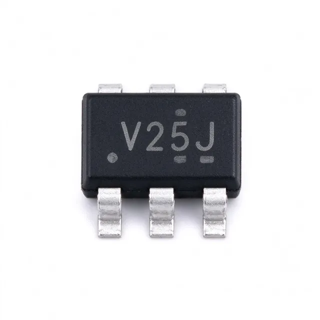
The Texas Instruments SN74AUP1T34QDCKRQ1 is an AEC-Q100 qualified 1-bit unidirectional non-inverting voltage-level translator with dual configurable power-supply rails supporting VCCA and VCCB from 0.9V to 3.6V each, housed in a 5-pin SC-70 (DCK) surface-mount package rated from -40C to +125C. A voltage-level translator (also called a level shifter) is a logic IC that interfaces digital signals between circuits operating at different supply voltages, for example connecting a 1.8V microcontroller output to a 3.3V peripheral input. Level translators sit within the broader logic IC family (buffers, translators, transceivers) and are essential wherever mixed-voltage domains coexist, which is nearly every modern embedded system. Key features include two independent supply rails (VCCA and VCCB) that can each be set anywhere from 0.9V to 3.6V, allowing any-to-any translation between common logic levels such as 1.2V, 1.5V, 1.8V, 2.5V and 3.3V. The push-pull (non-inverting) output drives the signal actively in both directions, eliminating the need for external pull-up resistors required by open-drain solutions. The AUP (Advanced Ultra-low-Power) silicon technology delivers low dynamic power consumption, making the device attractive for battery-powered automotive and portable designs. Architecturally, pin A is referenced to VCCA and receives the input signal, while pin B is referenced to VCCB and transmits the level-shifted output. Because both supplies support the same 0.9V to 3.6V range, the translator is direction-agnostic in voltage terms: it can translate low-to-high or high-to-low. TI controls the data sheet SN74AUP1T34-Q1, and the -Q1 suffix denotes AEC-Q100 automotive qualification including extended -40C to +125C operation. Typical applications include automotive body electronics and ADAS sensor interfaces, I2C/SPI/UART signal translation between mixed-voltage ICs, GPIO level conversion in battery-powered portable equipment, and general-purpose 1-bit buffering in industrial control modules. Design consideration: both VCCA and VCCB must be decoupled with 0.1uF ceramic capacitors placed close to pins 4 and 5, and the unused input should never be left floating since the AUP family inputs must be tied high or low. This page adds value beyond the TI datasheet by synthesizing distributor pricing as of 2026-09-04, drop-in alternative analysis, and practical layout notes in one place.

Permintaan RFG Kontak
SN74AUP2G126YZPR - Dual Bus Buffer 3-State 8-DSBGA | TI
SN74AUP2G126YZPR

SN74AUP2G126YZPR - Dual Bus Buffer 3-State 8-DSBGA | TI

The Texas Instruments SN74AUP2G126YZPR is a low-power dual bus buffer gate with 3-state outputs, offered in an 8-bump DSBGA (YZP) package. Each of its two channels is a non-inverting buffer with an independent output-enable input, allowing designers to place individual channels in a high-impedance state for bus-isolation or multiplexing duties. The AUP logic family targets battery-powered portable applications where dynamic and static current draw both matter. A bus buffer (or line driver) is a digital circuit element that reproduces a logic input at its output while providing higher drive strength, level translation, or bus-isolation capability. Within the broader taxonomy, a bus buffer belongs to the logic ICs category (sub-family: buffers/drivers/receivers) and falls under the CMOS logic umbrella alongside gates, inverters, and transceivers. Buffers are functionally distinct from transceivers: a buffer is unidirectional, while a transceiver is bidirectional and typically includes bus-side termination. The AUP family is TI's premier low-power CMOS sub-family, designed for sub-1 GHz edge rates and sub-microamp quiescent current budgets, sitting between the AUC (1.8-V optimized) and LVC (general-purpose) families in TI's logic-portfolio positioning. Key features include an operating voltage range of 0.8 V to 3.6 V across VCC, partial-power-down support via Ioff (live-insertion safe), 3.6-V tolerant inputs when VCC is at 3.3 V, low static and dynamic power consumption characteristic of AUP logic, and a maximum quiescent current in the microamp range. Each output stage uses TI's standard 3-state architecture, with an active-high output enable (OE) per channel. The 8-ball DSBGA package keeps the footprint extremely small - approximately 0.9 mm x 0.9 mm - making the part suitable for space-constrained wearables and handhelds. Architecturally, the SN74AUP2G126 uses TI's AUP silicon-gate CMOS process with industry-standard Schmitt-trigger inputs (partial), low-drive-strength CMOS outputs, and the Ioff feature that prevents back-feeding current into a powered-down output pin. Inputs are tolerant up to 3.6 V regardless of VCC, providing robust interface to 1.8 V, 2.5 V, and 3.3 V domain signals without external protection. Typical applications include smartphones and wearables, IoT sensor nodes, low-power portable instrumentation, voltage-level shifting between 1.2 V microcontrollers and 3.3 V peripherals, and any system needing bus multiplexing or isolation with minimal quiescent power. The 3-state outputs allow direct bus sharing with other drivers under careful OE arbitration. Designers should note that the DSBGA package requires reflow soldering with appropriate profile and that the small land pattern demands careful PCB layout and precise stencil design to avoid defects. When designing with this part, ensure that the OE pins are properly managed during power-up to prevent bus contention; pull OE to a defined logic level at startup rather than leaving them floating.

Permintaan RFG Kontak
SN74AVC2T245RSWR - 2-Bit Dual-Supply Level Shifter | Texas Instruments
SN74AVC2T245RSWR

SN74AVC2T245RSWR - 2-Bit Dual-Supply Level Shifter | Texas Instruments

The Texas Instruments SN74AVC2T245RSWR is a dual-bit, dual-supply noninverting bus transceiver with configurable voltage translation and 3-state outputs, housed in a 10-pin UQFN (RSW) package measuring just 1.8 mm x 1.4 mm. It operates from two independent supply rails (VCCA and VCCB) of 1.2 V to 3.6 V, enabling bidirectional logic-level translation between any two voltage domains. A dual-supply bus transceiver is a logic device that transfers data bidirectionally between two ICs operating at different logic levels, such as a 1.8 V microcontroller and a 3.3 V peripheral. It belongs to the broader hierarchy of voltage translators within interface logic ICs, and the SN74AVC2T245 is a member of TI's AVC (Advanced Very-low-voltage CMOS) family, optimized for high speed and low static power. Key features include independent direction control for each channel (DIR1 and DIR2), an output-enable (OE) pin for 3-state bus isolation, and a VCC isolation feature that forces all I/O ports to high impedance when either supply is at GND. The device achieves data rates up to 380 Mbps with a typical propagation delay of 2.4 ns and delivers 12 mA output drive at 3.3 V. The AVC architecture uses configurable level shifting: output levels are set automatically by VCCA and VCCB with no direction-strapping constraints. Ioff circuitry supports partial power-down operation by blocking backflow current when either rail collapses, and quiescent current is approximately 20 uA for battery-friendly designs. Typical applications include level shifting for I2C, SPI, UART, and GPIO buses in personal electronics, industrial control, and networking equipment. The 1.8 mm x 1.4 mm UQFN footprint suits space-constrained portable and wearable designs. Design consideration: keep both supplies within 1.2 V to 3.6 V at all times, and use the OE pin with a pull-down so the bus stays tri-stated during power-up to avoid contention.

Permintaan RFG Kontak
SN74AVC4T234 - 4-Bit Dual-Supply Level Translator | TI
SN74AVC4T234

SN74AVC4T234 - 4-Bit Dual-Supply Level Translator | TI

The SN74AVC4T234 is a 4-bit, dual-supply noninverting voltage level translation device from Texas Instruments. It is designed to facilitate asynchronous communication between B-port inputs and A-port outputs, with each port referenced to its own supply rail (VCCB and VCCA). The device operates across a wide VCC range of 0.9 V to 3.6 V, making it suitable for low-power, battery-powered portable applications where both static and dynamic power consumption must be minimized. A voltage level translator, also known as a level shifter, is a type of logic IC that allows digital signals to be transferred between circuits operating at different voltage levels. It is essential in mixed-voltage systems, such as interfacing a 1.8V microcontroller with a 3.3V peripheral. The SN74AVC4T234 belongs to the AVC family of advanced very-low-voltage CMOS logic, which is optimized for high-speed operation with minimal power consumption. Key features of the SN74AVC4T234 include its dual-supply configuration, which provides independent power rails for each port, ensuring proper voltage translation without signal distortion. The device maintains excellent signal integrity across the entire VCC range, and its low static and dynamic power consumption extends battery life in portable devices. The noninverting architecture preserves signal polarity, simplifying system design. Technically, the SN74AVC4T234 uses a configurable voltage translation scheme that automatically adjusts output drive strength based on the supply voltage. This ensures reliable operation even with varying supply levels. The device is available in a small package, making it ideal for space-constrained applications. Its propagation delay is minimal, supporting high-speed data transfer. Typical applications include interfacing between different voltage domains in smartphones, tablets, and other portable electronics, as well as in industrial control systems where sensors and microcontrollers operate at different voltages. The device is also used in networking equipment and data communication systems. When designing with the SN74AVC4T234, ensure that both VCCA and VCCB are powered and within the specified range. Proper decoupling capacitors should be placed near the supply pins to maintain stable operation. The device supports bidirectional level translation, but the direction is controlled by the DIR pin, which must be set correctly for the desired data flow.

Permintaan RFG Kontak
SN74AVC4T245PWR - 4-Bit Dual-Supply Level Shifter | TI
SN74AVC4T245PWR

SN74AVC4T245PWR - 4-Bit Dual-Supply Level Shifter | TI

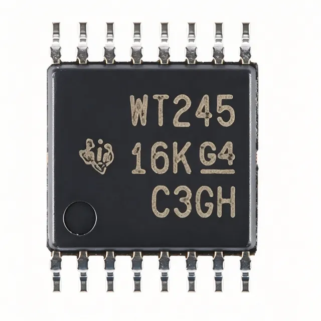
The Texas Instruments SN74AVC4T245PWR is a 4-bit dual-supply bus transceiver with configurable voltage translation and 3-state outputs, supplied in a 16-pin TSSOP (PW) package. It operates from two independent supply rails, VCCA and VCCB, each ranging from 0.8V to 3.6V, enabling bidirectional level shifting between mixed voltage domains such as 1.2V, 1.5V, 1.8V, 2.5V, and 3.3V. A bus transceiver is a digital integrated circuit that transfers data bidirectionally between two buses, using direction-control and output-enable inputs plus 3-state outputs so multiple devices can share a common bus. The SN74AVC4T245 belongs to the voltage translator (level shifter) family within the broader logic IC and interface IC hierarchy, and it is essential in mixed-voltage systems where MCUs, FPGAs, sensors, and memory operate at different logic levels. Key features include configurable voltage translation on both ports, control inputs (1DIR, 2DIR, 1OE, 2OE) referenced to VCCA for simplified control logic, and Ioff partial-power-down circuitry that disables outputs and prevents damaging backflow current when either rail is at GND. A VCC isolation feature places all I/O in high-impedance if either supply is absent. Technically, the device supports asynchronous communication between two data buses at data rates up to 380 Mbps with a typical propagation delay around 2.5 ns, suiting high-speed SPI, parallel bus, and GPIO interfaces. The TSSOP-16 package has a 4.4mm body width and 0.65mm pin pitch for space-constrained PCBs. Typical applications include level shifting for SPI, UART, I2C-adjacent GPIO expansion, and FPGA or ASIC interconnects in industrial control, portable battery-powered electronics, and automotive modules where multiple voltage domains coexist. Design tip: keep the DIR and OE pins driven from VCCA-domain logic and place 0.1uF decoupling capacitors close to both VCCA and VCCB pins; avoid bus contention by sequencing direction changes with a brief high-impedance interval.

Permintaan RFG Kontak
SN74AVC4T245PWR - 4-Bit Dual-Supply Level Shifter | TI
SN74AVC4T245PWR

SN74AVC4T245PWR - 4-Bit Dual-Supply Level Shifter | TI

The Texas Instruments SN74AVC4T245PWR is a 4-bit dual-supply bus transceiver with configurable voltage translation and 3-state outputs, supplied in a 16-pin TSSOP (PW) package. It operates from two independent supply rails, VCCA and VCCB, each ranging from 0.8V to 3.6V, enabling bidirectional level shifting between mixed voltage domains such as 1.2V, 1.5V, 1.8V, 2.5V, and 3.3V. A bus transceiver is a digital integrated circuit that transfers data bidirectionally between two buses, using direction-control and output-enable inputs plus 3-state outputs so multiple devices can share a common bus. The SN74AVC4T245 belongs to the voltage translator (level shifter) family within the broader logic IC and interface IC hierarchy, and it is essential in mixed-voltage systems where MCUs, FPGAs, sensors, and memory operate at different logic levels. Key features include configurable voltage translation on both ports, control inputs (1DIR, 2DIR, 1OE, 2OE) referenced to VCCA for simplified control logic, and Ioff partial-power-down circuitry that disables outputs and prevents damaging backflow current when either rail is at GND. A VCC isolation feature places all I/O in high-impedance if either supply is absent. Technically, the device supports asynchronous communication between two data buses at data rates up to 380 Mbps with a typical propagation delay around 2.5 ns, suiting high-speed SPI, parallel bus, and GPIO interfaces. The TSSOP-16 package has a 4.4mm body width and 0.65mm pin pitch for space-constrained PCBs. Typical applications include level shifting for SPI, UART, I2C-adjacent GPIO expansion, and FPGA or ASIC interconnects in industrial control, portable battery-powered electronics, and automotive modules where multiple voltage domains coexist. Design tip: keep the DIR and OE pins driven from VCCA-domain logic and place 0.1uF decoupling capacitors close to both VCCA and VCCB pins; avoid bus contention by sequencing direction changes with a brief high-impedance interval. This page synthesizes distributor pricing, drop-in alternatives, and practical design notes not found in the manufacturer datasheet.

USD $0,38 Kontak
SN74AVC8T245DGVR - 8-Bit Dual-Supply Bus Transceiver | TI
SN74AVC8T245DGVR

SN74AVC8T245DGVR - 8-Bit Dual-Supply Bus Transceiver | TI

The Texas Instruments SN74AVC8T245DGVR is an 8-bit dual-supply bus transceiver with configurable voltage-level shifting and 3-state outputs, housed in a 24-pin TVSOP (DGV) package. It supports data translation between two independently configurable voltage rails from 1.2 V to 3.6 V on VCCA and 1.2 V to 3.6 V on VCCB, with direction control via the DIR pin and output enable via the active-low OE pin. The device delivers high-speed signal transmission with typical propagation delay of approximately 2.5 ns at 3.3 V and ±12 mA output drive strength. A dual-supply bus transceiver is a logic IC that bridges two voltage domains in a digital system, allowing a microcontroller or ASIC on one rail (for example 1.8 V) to communicate with peripherals or memory on another rail (for example 3.3 V). The 'dual-supply' architecture uses two independent VCC pins (VCCA and VCCB) so each side of the transceiver references its own rail. Within the broader product taxonomy, this part belongs to the level shifter / voltage translation transceiver family, which sits under interface ICs and ultimately under integrated circuits. Key features of the SN74AVC8T245 include Ioff partial-power-down support for live insertion and hot-swap scenarios, VCC isolation that forces all I/O into high-impedance when either supply is at GND, and bus-hold circuitry on the data I/Os to eliminate the need for external pull-up or pull-down resistors. The DIR pin controls signal direction (A-to-B or B-to-A), and OE disables the outputs when high. The wide 1.2 V to 3.6 V operating range covers all common logic standards including 1.2 V, 1.5 V, 1.8 V, 2.5 V, 3.3 V, and lower-voltage CMOS. Architecturally, the device uses TI's AVC (Advanced Very-low-voltage CMOS) process technology, which combines low static power consumption with high drive strength and fast edge rates. The integrated bus-hold cells use weak feedback transistors to retain the last driven logic state on floating lines, eliminating external bias resistors. Ioff circuitry blocks the internal parasitic diode paths when VCC is removed, so the part can be safely inserted or removed from a powered backplane. Typical applications include level shifting between a 1.8 V host processor and 3.3 V peripherals, I2C or general-purpose GPIO expansion, SD-card or SIM-card interfaces, and translating logic between FPGAs and DDR memory rails. The wide voltage range makes it useful in industrial, consumer, and portable battery-powered designs. When designing with this part, place a 0.1 µF decoupling capacitor on each VCC pin and route the DIR and OE pins directly to a GPIO of the controlling host. Avoid leaving either VCC pin floating; unused VCC must be tied to its corresponding rail or to GND to ensure proper high-impedance behavior. This page synthesizes distributor pricing, drop-in alternatives, and practical design notes that go beyond the manufacturer datasheet, helping engineers select and source the part efficiently.

Permintaan RFG Kontak
SN74AVCB164245GR - 16-Bit Dual-Supply Level Translator | Texas Instruments
SN74AVCB164245GR

SN74AVCB164245GR - 16-Bit Dual-Supply Level Translator | Texas Instruments

The Texas Instruments SN74AVCB164245GR is a 16-bit dual-supply bus transceiver with configurable voltage translation and 3-state outputs, housed in a 48-pin TSSOP (DGG) package. It supports bidirectional level translation between two supply rails from 1.4 V to 3.6 V on the A-port and 1.4 V to 3.6 V on the B-port, with separate VCCA and VCCB power pins per port group enabling asymmetric voltage domains. A bidirectional level translator (also called a voltage level shifter) is an integrated circuit that safely bridges two subsystems operating at different logic-voltage rails. The SN74AVCB164245 belongs to the widebus transceiver family and provides 16 channels split into two 8-bit groups, each with its own direction-control pin. This device class is essential in mixed-voltage systems where modern processors operate at 1.8 V or 1.2 V while legacy peripherals, memories, or bus interfaces remain at 2.5 V or 3.3 V. Key features include a typical propagation delay of 3.7 ns (VDD = 3.3 V), ±12 mA drive strength per channel, 3.5 ns maximum output skew, and partial-power-down capability through Ioff circuitry that prevents damaging backflow current when the device is unpowered. The DIR inputs set the direction of data flow per 8-bit bank, while the OE pins place outputs in high impedance for bus isolation. The SN74AVCB164245 uses TI's DOC (Dynamic Output Control) circuitry, which dynamically switches output impedance to reduce line-noise transients without external damping components. This active damping eliminates the typical ringing seen on heavily loaded memory buses, which improves signal integrity at high data rates. Typical applications include memory-card interfaces between SoCs and DDR/LPDDR memories, GPIO expansion between low-voltage MCUs and 3.3 V peripherals, FPGA-to-MCU bridge logic in industrial controllers, I2C/SPI/UART bridge isolation, and smartphone baseband-to-application-processor interconnects. The dual-supply design is particularly suited to portable electronics where minimizing both voltage drop and leakage current is critical. When designing with this device, ensure VCCA and VCCB rails are decoupled with 0.1 uF ceramic capacitors placed within 5 mm of the supply pins. The OE and DIR logic thresholds are referenced to their respective supply rails, so control signals must be level-shifted into the appropriate domain. Avoid leaving OE floating; tie through a 10 kohm resistor to the high-side supply rail of the controlling port. This page synthesizes distributor pricing, parametric alternatives, and practical design notes not found in the manufacturer datasheet. Pricing references are stated as of 2026-10-04.

Permintaan RFG Kontak
SN74AXC4T774BQBR - 4-Bit Dual-Supply Bus Transceiver | Texas Instruments
SN74AXC4T774BQBR

SN74AXC4T774BQBR - 4-Bit Dual-Supply Bus Transceiver | Texas Instruments

The Texas Instruments SN74AXC4T774BQBR is a 4-bit dual-supply bus transceiver with configurable voltage translation, independent direction control inputs, and 3-state outputs, housed in a 16-pin WQFN package (2.5 mm x 3.5 mm). It supports an input voltage range of 0.65 V to 3.6 V on the A-port and 0.65 V to 3.6 V on the B-port, allowing seamless level shifting between any two voltage nodes from 0.65 V up to 3.6 V without external direction-control logic. The SN74AXC4T774 belongs to the bus transceiver / level shifter category (a sub-family of voltage level translators within interface ICs / logic ICs). Level translators are interface ICs that allow digital signals to pass between two parts of a system that operate at different supply voltages. They are an essential building block in mixed-voltage designs where low-voltage processors and ASICs must communicate with legacy 1.8 V, 2.5 V, or 3.3 V peripherals, and they enable designers to maintain backwards compatibility while taking advantage of new low-voltage cores. Key features of the SN74AXC4T774 include a typical data rate of 110 Mbps, 4.4 ns typical propagation delay, partial-power-down support via Ioff, and a control-pin reference (DIR and OE) tied to VCCA for simple GPIO-driven control. The AXC family offers the industry's lowest static power consumption in this class, helping portable and battery-powered designs extend runtime without sacrificing throughput. The internal architecture uses TI's AXC CMOS technology with one-shot edge accelerators that detect rising or falling edges on the I/O pins and briefly speed up the output drivers to achieve high data rates with low dynamic power. The DIR pin determines signal direction, while OE enables a high-impedance output mode for bus isolation. Both A and B ports support 3.6-V tolerant I/O on the lower-voltage side, simplifying board design. Typical applications include I2C / SPI / UART bridging between low-voltage SoCs and 3.3 V peripherals, MIPI / camera-serializer voltage translation, SD-card level shifting, and general-purpose GPIO expansion in industrial controllers, wearables, and portable IoT endpoints. A key design consideration is to always tie the OE pin to VCCA through a pull-up resistor (or to a dedicated GPIO) so that the I/Os enter high-impedance during power-up or power-down, preventing bus contention and back-powering. This page synthesizes distributor pricing, same-brand and cross-brand drop-in alternatives in the WQFN-16 footprint, and practical design notes not collated in the manufacturer datasheet alone.

Permintaan RFG Kontak
SN74AXC8T245RJWR - 8-Bit Dual-Supply Bus Transceiver | Texas Instruments
SN74AXC8T245RJWR

SN74AXC8T245RJWR - 8-Bit Dual-Supply Bus Transceiver | Texas Instruments

The Texas Instruments SN74AXC8T245RJWR is an 8-bit non-inverting, bidirectional dual-supply bus transceiver with configurable voltage translation and 3-state outputs, housed in a 24-pin UQFN (RJW, 4x2 mm) package. It supports independent power-supply rails on each port from 0.65 V to 3.6 V, output drive current of 12 mA, and is fully specified for partial-power-down applications using Ioff. The device operates over an industrial -40C to +125C temperature range. A bus transceiver is a digital logic IC that bridges two buses operating at different voltage levels, allowing data to flow in either direction while protecting each side from incompatible logic levels. The SN74AXC8T245 belongs to TI's AXC family of voltage-level translators, which sit in the broader hierarchy: level translator -> bus transceiver -> logic IC -> semiconductor. The AXC series extends the older AVC and LVC families to lower supply nodes (0.7 V, 0.8 V, 0.9 V) used in modern ASICs, FPGAs, and processors while remaining backward-compatible with industry-standard 1.8 V, 2.5 V, and 3.3 V nodes. Key features include configurable direction control per direction (DIR pin), an active-low output-enable (OE) input that disables both ports to a high-impedance state, 12 mA balanced output drive strength, and ±24 mA DC latch-up protection. The Ioff circuitry disables the outputs when either VCC rail is powered down, preventing backflow current into a partially powered system - a critical requirement for hot-swap and multi-rail designs. Technical depth: the AXC architecture uses TI's advanced CMOS process with internal edge-rate accelerators that limit output rise/fall times to reduce EMI while preserving sufficient bandwidth for RGMII and similar multi-hundred-MHz interfaces. The dual-rail design means the DIR and OE control pins are always referenced to VCCA, simplifying control logic on the lower-voltage side. Typical applications include RGMII level shifting between an SoC and a PHY, I2C/SPI/UART bridging in mixed-voltage embedded systems, memory-bus isolation, and processor-to-peripheral translation in industrial and consumer designs. The 24-pin UQFN (4x2 mm) footprint keeps board area minimal. Design consideration: always populate both VCCA and VCCB decoupling capacitors (0.1 uF ceramic) within 2 mm of the respective pins, and ensure OE is held low until both rails have ramped to valid levels to avoid bus contention at startup. This page synthesizes distributor pricing, drop-in alternatives, and practical design notes not found in the manufacturer datasheet.

Permintaan RFG Kontak
SN74BCT574 - Octal D-Type Flip-Flop 3-State | Texas Instruments
SN74BCT574

SN74BCT574 - Octal D-Type Flip-Flop 3-State | Texas Instruments

The Texas Instruments SN74BCT574 is an octal D-type edge-triggered flip-flop with 3-state outputs, built on a state-of-the-art BiCMOS process and designed to drive highly capacitive or relatively low-impedance loads in high-speed bus-oriented systems. It operates from a 4.5 V to 5.5 V supply and is offered in DB (SSOP), DW (SOIC), N (PDIP), and NS (SOP) packages. An octal D-type flip-flop is a digital logic register that stores eight bits of data, capturing the logic level present on each D input at the rising edge of a common clock and presenting it on the corresponding Q outputs. In the broader logic-IC hierarchy, it belongs to the flip-flop and register family of sequential logic, a core building block of microprocessor bus interfaces. Its 3-state outputs can be disabled via an active-low output-enable (OE) pin, allowing multiple devices to share a common data bus without contention. Key features include the BiCMOS design that significantly reduces ICCZ (high-impedance supply current), full parallel access for loading all eight bits on one clock edge, and strong bipolar output drive for heavy capacitive bus loads. According to TI datasheet SCBS074C, the edge-triggered architecture guarantees that data is captured only on the rising clock edge, giving predictable setup and hold behavior in synchronous systems. Technical depth: the BCT (BiCMOS) technology combines TTL-compatible input thresholds with bipolar totem-pole output stages, delivering low dynamic supply current at high clock frequencies and high output current capability, making it superior to pure CMOS ABT/ACT predecessors for heavily loaded 5 V buses. Typical applications include buffer registers, I/O ports, bidirectional bus drivers, working registers in microprocessor systems, memory address/data latching, industrial control, and communication interfaces where reliable latching plus high bus drive are required. Design tip: control OE properly to avoid bus contention (OE low enables outputs, high forces high-Z), decouple VCC close to the pins with 0.1 uF ceramic capacitors, and drive the clock with a clean edge to avoid metastability.

Permintaan RFG Kontak
SN74CBT16209ADGV - 18-Bit FET Bus-Exchange Switch | Texas Instruments
SN74CBT16209ADGV

SN74CBT16209ADGV - 18-Bit FET Bus-Exchange Switch | Texas Instruments

The Texas Instruments SN74CBT16209ADGV is an 18-bit FET bus-exchange switch from the Widebus family, delivering high-speed TTL-compatible bus switching or exchanging in a 48-pin TVSOP (DGV) package. It functions as a 9 x 2:2 crosspoint/exchange switch capable of data exchange between four signal ports via three data-select (S0, S1, S2) terminals, making it suitable for high-performance digital systems requiring flexible signal routing. Background: a FET bus switch is a digital interface IC that uses MOSFET pass transistors to connect or isolate buses with minimal propagation delay and very low on-state resistance. Unlike analog muxes, FET bus switches are unidirectional signal paths optimized for 5V TTL logic levels. They sit in the hierarchy of digital logic ICs (TTL/CMOS logic -> bus interface -> bus switch -> FET bus-exchange switch), serving as the building blocks for memory interleaving, card-edge bus switching, and bus arbitration in backplane designs. Key specifications include 5V nominal VCC operation, TTL-compatible input levels on the select control pins, low on-state resistance for minimal propagation delay, and an approximate propagation delay of 0.35 ns as listed by distributors. The device provides five switch connection modes between two ports, allowing engineers to route 9-bit data slices between four signal ports. A low rON enables clean high-speed switching without driving large currents through the internal pass-FETs. Architecturally, the SN74CBT16209A uses N-channel MOSFET pass gates driven by TTL-compatible level shifters, with the S0-S2 select lines decoded to one of five switch configurations. The exchange/crosspoint topology (9 x 2:2) means the part can connect any one of two buses on each side of an exchange switch to either of two buses on the opposite side, providing bidirectional bus steering in a single IC. The Widebus footprint integrates all 18 bits in one package to minimize board space. Typical applications include high-speed memory bus switching, board-to-board data routing, server backplanes, bus isolation in hot-swap systems, and graphics-card memory interface multiplexing. The 48-pin TVSOP package is well-suited for high-density card-edge designs where fine-pitch surface-mount parts are required. Design consideration: the SN74CBT16209A requires a clean 5V supply with adequate decoupling (0.1uF ceramic close to VCC pins); unused inputs must be tied to VCC through a pull-up resistor to avoid floating-select states. When migrating between the DGG, DGV, DL, and WD package variants, verify pinout compatibility because the package options differ in pitch (TVSOP vs SSOP vs ceramic flat). Unique value: this page consolidates the SN74CBT16209ADGV datasheet parameters, alternative TVSOP-48 drop-in options, and proven PCB layout tips that go beyond the TI datasheet application notes.

Permintaan RFG Kontak
SN74CBT3245ADWR - Octal FET Bus Switch 5V SOIC-20 | TI
SN74CBT3245ADWR

SN74CBT3245ADWR - Octal FET Bus Switch 5V SOIC-20 | TI

The Texas Instruments SN74CBT3245ADWR is an octal FET bus switch providing eight bits of high-speed TTL-compatible bus switching in a 20-pin SOIC (DW) package with the standard 245-type pinout. Operating from a 4.5V to 5.5V supply, the device is organized as a single 8-bit switch with one output enable (OE) control input; when OE is low, the switch connects the two 8-bit ports bidirectionally. A FET bus switch is a type of analog switch that uses N-channel MOSFET pass transistors to connect or disconnect signal paths between two ports. Within the signal-routing hierarchy, bus switches sit between logic buffers and analog multiplexers: unlike buffers they add negligible propagation delay, and unlike analog MUXes they are optimized for high-bandwidth digital bus isolation. The SN74CBT3245A belongs to the CBT (CrossBar Technology) family, optimized for low on-state capacitance and high bandwidth. Key features include a low on-state resistance of typically 5 ohms, propagation delay of less than 250 ps, and near-zero added jitter because signals pass through an analog FET path rather than a buffered logic stage. The switch supports bidirectional data flow and 5-V level handling, suited to signal switching rather than power delivery. Technically, the device is fabricated in a CMOS process achieving low static power consumption. The internal FET switch presents a low-capacitance, low-resistance path that minimizes signal distortion, and the 245-type pinout matches industry-standard octal transceiver footprints across SOIC, SSOP, TSSOP, and TVSOP package options. Typical applications include bus isolation in microprocessor systems, hot-swap and power-down isolation on backplanes, memory bus switching, and signal routing in networking and telecommunications equipment where high-speed data buses must be connected or isolated under logic control. A key design consideration: control the OE pin properly to avoid bus contention, and note this part is EOL per TI.com - plan the drop-in alternatives listed on this page for new designs.

Permintaan RFG Kontak
SN74CBTLV1G125DBVR - 3.3V Single FET Bus Switch SOT-23-5 | TI
SN74CBTLV1G125DBVR

SN74CBTLV1G125DBVR - 3.3V Single FET Bus Switch SOT-23-5 | TI

The Texas Instruments SN74CBTLV1G125DBVR is a 3.3-V, single-channel, 1:1 (SPST) FET bus switch housed in a 5-pin SOT-23 (DBV) package. It provides a 5-ohm (typ) on-state resistance rail-to-rail switch path between two ports, with an active-low output enable (OE) input and Ioff support for partial-power-down mode operation. A bus switch (also called a FET switch or pass-gate switch) is a digital building block that replaces mechanical relays and discrete MOSFET switches in CMOS logic designs. The CBTLV family uses parallel n-channel and p-channel MOSFETs to provide a low-resistance bidirectional connection when enabled, achieving propagation delays under 0.25 ns. Bus switches sit within the logic-IC hierarchy as signal switches, above multiplexers and below general-purpose logic gates, and are essential for level shifting, signal multiplexing, and isolating subsystems on shared digital buses. Key features include 5-ohm typ on-resistance (ron) measured at VCC = 3.3 V, rail-to-rail switching on data I/O ports, low quiescent current of 10 uA max, and 5.5 V tolerant I/O when VCC = 0 V thanks to the Ioff isolation. The SN74CBTLV1G125 is one of the smallest 1-channel bus switches available, making it ideal for space-constrained mobile and portable designs where a single high-speed line must be routed or isolated. Architecturally, the device uses a parallel NMOS/PMOS pass gate controlled by a single OE-bar input. When OE-bar is low, both FETs turn on, creating a low-resistance channel between pin A (input) and pin Y (output); when OE-bar is high, the channel opens and the switch enters a high-impedance state. The Ioff circuitry prevents backfeeding through the switch when VCC is removed, eliminating parasitic current paths in partial-power-down or hot-swap scenarios. Typical applications include USB type-C signal routing and protection, I2C/UART bus isolation in battery-powered devices, SD card muxing, GPIO expansion, and reset signal gating in microcontroller-based designs. The SOT-23-5 footprint makes the part convenient for hand-rework on prototype boards. When designing with this device, place a 1 nF to 10 nF decoupling capacitor as close as possible to the VCC pin and observe ESD precautions when handling the small-outline package. Pull-up on OE-bar ensures defined behavior during power-up sequencing in microcontrollers with high-impedance control pins. This page synthesizes distributor pricing, drop-in alternatives, and practical design notes not found in the manufacturer datasheet alone.

USD $0,26 Kontak
SN74CBTLV3257PWR - 4-Bit 2:1 FET Mux 5Ω | TI
SN74CBTLV3257PWR

SN74CBTLV3257PWR - 4-Bit 2:1 FET Mux 5Ω | TI

The Texas Instruments SN74CBTLV3257PWR is a low-voltage 4-bit 1-of-2 FET multiplexer/demultiplexer designed for 3.3-V operation. It provides four independent 2:1 (SPDT) analog switch channels in a compact 16-pin TSSOP (PW) package, enabling high-speed signal routing with minimal propagation delay and low ON-state resistance. A multiplexer/demultiplexer is a signal-routing switch that directs one of several inputs to a common output, or vice versa. Within the logic and signal-switching hierarchy, the SN74CBTLV3257 belongs to the CBTLV family of bus (FET) switches, which sit between simple logic gates and full analog multiplexer ICs, optimized for low capacitance and low ON-resistance to preserve signal integrity. Key features include a typical ON-state resistance of 5 ohms, an operating supply range of 2.3 V to 3.6 V, and a partial-power-down mode that places I/Os in high impedance when VCC is 0 V. I/Os are over-voltage tolerant to 5 V, allowing mixed-voltage signaling. The 16-pin TSSOP package measures 5 mm x 6.4 mm with a 0.65-mm pitch for space-constrained PCBs. The device uses a pass-gate (FET) architecture that is fully bidirectional, with typical propagation delay of 0.25 ns and low channel-to-channel crosstalk. An output-enable (OE) pin drives all outputs to high impedance when low, supporting bus isolation, while the select (S) pin routes each channel between its A and B ports. Typical applications include high-speed signal routing in networking equipment, data acquisition systems, test instrumentation, and mixed-voltage bus switching in computing platforms. Low ON-resistance suits clock and data distribution where edge fidelity matters. Design tip: tie OE to VCC through a pull-up resistor to guarantee high-impedance OFF-state during power-up and power-down, per the TI/NXP datasheet, preventing bus contention during multi-rail power sequencing. Pricing as of 2026-08-30 starts near $0.27 per unit at volume.

Permintaan RFG Kontak
SN74F27 - Triple 3-Input NOR Gate | Texas Instruments
SN74F27

SN74F27 - Triple 3-Input NOR Gate | Texas Instruments

The SN74F27 is a triple 3-input positive-NOR gate from Texas Instruments, part of the 74F family of bipolar logic devices. It operates from a 4.5-V to 5.5-V supply and is characterized for operation from 0°C to 70°C. The device contains three independent 3-input NOR gates that perform the Boolean function Y = A + B + C in positive logic. Available in multiple package options including SOIC, PDIP, and ceramic DIPs, the SN74F27 is designed for high-speed logic applications where propagation delay and output drive are critical. A NOR gate is a digital logic gate that outputs a HIGH signal only when all of its inputs are LOW. In the context of logic families, the 74F series is a high-speed bipolar family that offers a balance between speed and power consumption, making it suitable for applications that require fast switching without the higher power of ECL. The SN74F27 is a fundamental building block in digital systems, used to implement logic functions, combinational circuits, and as a component in larger integrated systems. Key features of the SN74F27 include a typical propagation delay of 5.5 ns, which enables high-speed operation in clocked systems. The device provides a standard TTL-compatible output that can drive up to 20 mA, allowing direct connection to other TTL logic or LEDs. The wide operating voltage range of 4.5 V to 5.5 V ensures compatibility with 5-V logic systems, and the device is available in industry-standard packages such as SOIC-14 and PDIP-14, facilitating easy PCB integration. Technically, the SN74F27 uses a bipolar junction transistor (BJT) process, which provides high output drive capability and fast edge rates. The device features a totem-pole output stage that can source and sink current, ensuring robust signal integrity in noisy environments. The input structure includes clamping diodes for ESD protection, and the device is designed to meet the JEDEC standard for TTL logic levels, ensuring interoperability with other 74-series logic. Typical applications for the SN74F27 include address decoding in memory systems, logic function generation in control units, and as a building block in arithmetic logic units (ALUs). Its high speed makes it suitable for data path logic in processors and digital signal processing circuits. The device is also used in test and measurement equipment where precise timing is required. When designing with the SN74F27, it is important to ensure proper decoupling of the power supply with a 0.1-µF capacitor placed close to the VCC pin. Unused inputs should be tied to a defined logic level, either VCC or GND, to prevent floating inputs that can cause excessive power consumption and unpredictable behavior. The device's output can drive up to 20 mA, but for higher current loads, a buffer or driver should be used.

Permintaan RFG Kontak
SN74HC109 - Dual J-K Flip-Flop with Clear/Preset | TI
SN74HC109

SN74HC109 - Dual J-K Flip-Flop with Clear/Preset | TI

The SN74HC109 is a dual J-K positive-edge-triggered flip-flop with clear and preset, manufactured by Texas Instruments. It operates over a wide voltage range of 2V to 6V, features low input current of 1 µA max, and can drive up to 10 LSTTL loads. Available in multiple packages including 16-pin DIP (N), SOIC (D), and SOP (NS). A J-K flip-flop is a sequential logic device that toggles its output based on the J and K inputs at the rising edge of the clock. It is a fundamental building block in digital electronics, used for counters, registers, and state machines. The SN74HC109 belongs to the 74HC family of high-speed CMOS logic, which combines the speed of LSTTL with the low power consumption of CMOS. Key features include two independent flip-flops with preset (PRE) and clear (CLR) inputs, positive-edge triggering, and a typical propagation delay of 12 ns. The device operates from 2V to 6V, with a maximum quiescent current of 40 µA, making it suitable for battery-powered applications. The outputs can drive up to 10 LSTTL loads, ensuring compatibility with TTL logic. The SN74HC109 uses high-speed CMOS technology, providing a balanced combination of speed and power efficiency. The positive-edge-triggered design ensures predictable timing behavior, while the asynchronous PRE and CLR inputs allow immediate setting or resetting of outputs regardless of clock state. This makes it ideal for applications requiring reliable state control. Typical applications include digital counters, frequency dividers, shift registers, and control logic in industrial automation, consumer electronics, and communication systems. Its wide voltage range and low power consumption make it suitable for portable and battery-operated devices. When designing with the SN74HC109, ensure proper decoupling of the power supply with a 0.1 µF capacitor near the VCC pin. Unused inputs should be tied to VCC or GND to avoid floating states. The setup and hold times must be respected to guarantee reliable operation.

Permintaan RFG Kontak
SN74HC126QPWRQ1 - Quad 3-State Buffer AEC-Q100 | Texas Instruments
SN74HC126QPWRQ1

SN74HC126QPWRQ1 - Quad 3-State Buffer AEC-Q100 | Texas Instruments

The Texas Instruments SN74HC126QPWRQ1 is an AEC-Q100 qualified quadruple bus buffer gate with 3-state outputs, containing four independent non-inverting buffers with individual active-high output-enable (OE) pins, housed in a 14-pin TSSOP (PW) package. The device operates from a 2 V to 6 V single supply and provides CMOS-logic-compatible buffering for bus driving, line driving, and signal isolation in automotive electronic systems. A buffer with 3-state outputs is a digital logic element that passes its input level to the output when enabled and presents a high-impedance (Hi-Z) state when disabled, allowing multiple devices to share a common bus. Within the logic hierarchy, it belongs to the buffer/line-driver family of high-speed CMOS (HC) logic, itself a branch of the broader CMOS voltage-regulated logic category used in nearly every digital system. Key features include four independent 1-bit buffers with separate OE control per channel, active-high enable inputs (the OE low state disables the output), and automotive qualification per AEC-Q100 for operation in harsh environments. The HC CMOS process delivers low static power consumption and balanced drive characteristics across the 2 V to 6 V operating range, with TTL-friendly noise margins at 5 V. The 74HC126 architecture derives from the industry-standard 74126 pinout: each gate passes input A to output Y when OE is high; when OE is low the output enters Hi-Z. TI recommends tying OE to GND through a pull-down resistor during power-up and power-down to guarantee the high-impedance state, preventing bus contention in shared-bus systems such as microcontroller data buses and memory interfaces. Typical applications include automotive body electronics and infotainment bus isolation, industrial PLC I/O line driving, and microcontroller GPIO buffering where tri-state control prevents driver conflicts. The TSSOP-14 package suits space-constrained automotive modules. Design consideration: keep unused inputs (especially OE) tied to a defined logic level through a pull resistor; floating enables can cause unpredictable bus contention and increased supply current. This page synthesizes distributor pricing, drop-in alternatives including Schmitt-trigger and AHC variants, and practical design notes not found in the manufacturer datasheet. Pricing data is as of 2026-09-10.

Permintaan RFG Kontak
SN74HC165PW - 8-Bit Parallel-Load Shift Register | Texas Instruments
SN74HC165PW

SN74HC165PW - 8-Bit Parallel-Load Shift Register | Texas Instruments

The Texas Instruments SN74HC165PW is an 8-bit parallel-load shift register from the SN74HC series, housed in a 16-pin TSSOP (PW) package. Operating across a wide 2V to 6V VCC range with complementary QH and QH-bar serial outputs, it converts parallel inputs to a serial stream and is rated for ±4 mA output drive at 5 V. According to the TI datasheet for the SN74HC165 family, the device supports asynchronous parallel loading via a low SH/LD-bar pulse followed by synchronous serial shifting on the CLK rising edge. A parallel-load shift register is a sequential logic device that captures multi-bit data simultaneously and then releases that data one bit per clock cycle on a serial output. These devices fall under the hierarchy of digital logic ICs -> shift registers -> parallel-in/serial-out (PISO) converters -> signal conditioning and I/O expansion. They are essential building blocks in the broader landscape of CMOS logic, including counters, multiplexers, and decoders, where GPIO counts are limited but multiple input signals must be read efficiently by a microcontroller. Key features include gated clock inputs (CLK and CLK INHIBIT), a serial-in (SER) input for cascading, direct overriding parallel data inputs (A through H), and CMOS-compatible low-power consumption with 80 µA maximum ICC. The device is also specified for a typical propagation delay of around 13 ns at 5 V and tolerates 10 LSTTL loads, giving significant drive margin. Its TSSOP-16 footprint is a popular surface-mount choice for compact designs. Typical applications include expanding microcontroller input ports for reading multiple pushbuttons, keypad scanning, DIP-switch polling, and reading multi-channel sensor arrays (e.g., 8-channel temperature or switch-contact inputs) using only two or three GPIO pins. The wide operating voltage and CMOS-friendly thresholds make it useful in 3.3 V and 5 V mixed-signal boards. When designing with the SN74HC165PW, debounce mechanical inputs at the source or via software filtering because the shift register has no built-in debounce. The complementary outputs (QH and QH-bar) are useful for differential signalling or chained-shift cascading across multiple devices without extra glue logic.

Permintaan RFG Kontak
SN74HC165PWR - 8-Bit Parallel-Load Shift Register | TI | TSSOP-16
SN74HC165PWR

SN74HC165PWR - 8-Bit Parallel-Load Shift Register | TI | TSSOP-16

The Texas Instruments SN74HC165PWR is an 8-bit parallel-load shift register in a 16-pin TSSOP (PW) package, providing wide operating voltage range of 2V to 6V with typical tpd of 13 ns at 5V. It features complementary serial outputs (Q7 and Q7-bar) and gated clock enable, making it a workhorse for parallel-to-serial expansion in microcontroller-based designs. A shift register is a sequential logic device that converts between parallel and serial data formats, falling within the broader categories of sequential logic, digital logic IC, and finally semiconductor. The HC family (High-speed CMOS) operates at CMOS logic levels with TTL-compatible thresholds, providing low power consumption (80 uA max Icc) and balanced output drive. The '165 implements a parallel-in/serial-out (PISO) architecture: eight data inputs (A-H) are loaded asynchronously, then serially clocked out on the QH pin. This conversion allows a microcontroller with limited GPIO pins to read many switches, sensors, or buttons using only two or three pins. Key specifications include a wide 2V-6V operating voltage range, typical propagation delay of 13 ns at 5V, ±4-mA output drive at 5V, low input current of 1 uA max, and the ability to drive up to 10 LSTTL loads. The device also features complementary outputs (Q7 and Q7-bar), direct overriding load data inputs, and a gated clock enable pin for hardware-level clock gating. The SN74HC165 uses a master-slave flip-flop architecture with eight D-type latches feeding an internal shift register. The asynchronous load feature (active-low SH/LD-bar) overrides clocking, allowing immediate parallel capture. This dual-mode operation makes it equally suitable for capturing transient input states (button presses) and streaming serial data (sensor daisy chains). The wide VCC range supports both 3.3V and 5V systems, with TTL-compatible inputs simplifying connection to legacy logic. Typical applications include multi-button input scanning (keypads), input expansion for microcontrollers with limited GPIO, LED matrix driving, industrial control panel scanning, and serial data daisy-chaining for sensor arrays. The cascadable serial output allows multiple '165 devices to be chained, expanding input capacity without additional microcontroller pins. When designing with this part, consider the SH/LD-bar timing: data must be stable before SH/LD-bar returns high to avoid metastable propagation. Place a 0.1 uF decoupling capacitor close to VCC pin, and use series termination resistors on long clock lines to limit ringing. This page synthesizes TI datasheet specifications, current distributor pricing, verified drop-in alternatives, and practical design notes beyond what a single manufacturer datasheet provides.

Permintaan RFG Kontak
SN74HC21-Q1 - Dual 4-Input AND Gate, 2-6V | TI
SN74HC21-Q1

SN74HC21-Q1 - Dual 4-Input AND Gate, 2-6V | TI

The Texas Instruments SN74HC21-Q1 is an automotive-qualified dual 4-input positive-AND gate in the HC (High-Speed CMOS) logic family, operating from a wide 2 V to 6 V supply with 5.2 mA output drive strength. The device contains two independent 4-input AND gates performing the Boolean function Y = A • B • C • D in positive logic, and is AEC-Q100 qualified for automotive applications. A logic gate is the fundamental building block of digital circuits, performing a Boolean operation on one or more binary inputs to produce a single binary output. Within the logic IC hierarchy, the AND gate family, the 74HC High-Speed CMOS series, and the broader CMOS logic category place this device among the most widely standardized components in electronics. The HC family combines CMOS low static power with TTL-like speed, making 74HC devices broadly interchangeable across semiconductor vendors. Key features include a wide 2 V to 6 V operating range supporting 3.3 V, 5 V, and mixed-voltage automotive rails, a typical propagation delay of 11 ns at 5 V, and ±4 mA output drive at 5 V allowing the outputs to drive up to ten LSTTL loads. Input current is extremely low at 1 uA maximum, and quiescent supply current is only 20 uA maximum, minimizing standby power in always-on automotive modules. Technically, the device uses HC CMOS architecture with rail-to-rail CMOS input thresholds, providing high noise immunity (typically 28% of VCC) and balanced drive. The automotive catalog variant is characterized across the extended AEC-Q100 temperature range with enhanced process controls and documentation. Typical applications include safety-interlock gating in automotive body modules, enable gating for power sequences, sensor qualification logic in ADAS perception modules, and general glue logic in ECU, gateway, and instrument-cluster boards. Design tip: tie all unused gate inputs to VCC or GND - never leave CMOS inputs floating, or both transistors can conduct and increase current draw. Keep decoupling (100 nF) close to VCC pin 14 for switching-transient control.

Permintaan RFG Kontak
SN74HC21DR - Dual 4-Input AND Gate SOIC-14 | Texas Instruments
SN74HC21DR

SN74HC21DR - Dual 4-Input AND Gate SOIC-14 | Texas Instruments

The Texas Instruments SN74HC21DR is a dual 4-input positive-AND logic gate belonging to the high-speed CMOS (74HC) family, operating from a 2 V to 6 V supply with 5.2 mA output drive strength, delivered in a 14-pin SOIC (D) package rated from -40C to +85C. A logic AND gate is a fundamental digital building block whose output asserts HIGH only when all of its inputs are HIGH. The SN74HC21 integrates two such gates on one silicon die, making it part of the broader logic IC hierarchy: gate -> combinational logic -> small-scale integration (SSI) -> 74HC CMOS family -> digital logic IC. Its function directly replaces the older LS/TTL 74LS21 in 5 V systems while adding CMOS advantages. Key features include a wide 2 V to 6 V operating range covering 3.3 V, 5 V, and legacy 6 V rails; outputs that can drive up to 10 LSTTL loads; typical propagation delay of 11 ns at 5 V; plus/minus4 mA output drive at 5 V; and very low power consumption with a maximum ICC of only 20 uA. Maximum input current is just 1 uA, easing fan-out and pull-up resistor design. Technically, the HC family uses CMOS technology with inputs that include clamp diodes, permitting interface to voltages slightly above VCC through current-limiting resistors. The balanced push-pull output stage delivers symmetric rise/fall times and rail-to-rail output swing, unlike bipolar TTL which loses headroom. Typical applications include enable-signal gating in industrial controllers, safety interlock logic where multiple conditions must all be true, address decoding, and general glue logic in 3.3 V and 5 V embedded systems. Design-wise, keep unused inputs tied to VCC or GND; never leave 4-input AND inputs floating, or noise can propagate to the output. Decouple VCC with 100 nF ceramic close to pin 14. This page synthesizes distributor pricing, verified drop-in alternatives, pinout data, and practical design notes not found in the manufacturer datasheet alone.

Permintaan RFG Kontak
SN74HC21PWR - Dual 4-Input AND Gate, 2-6V | TI
SN74HC21PWR

SN74HC21PWR - Dual 4-Input AND Gate, 2-6V | TI

The Texas Instruments SN74HC21PWR is a dual 4-input positive-AND gate logic IC operating from a 2V to 6V supply, delivering 5.2 mA output drive strength at 6V in a 14-pin TSSOP (PW) package rated from -40C to +85C. An AND gate is a fundamental combinational logic device that outputs a logic HIGH only when all of its inputs are logic HIGH. Within the digital IC hierarchy, the SN74HC21 belongs to the family of gates and inverters, which are the simplest building blocks of the broader CMOS logic category and form the basis of state machines, address decoding, enable-logic generation, and glue logic in embedded systems. The HC (High-Speed CMOS) family combines CMOS low static power with TTL-compatible drive capability. Key features of the SN74HC21 include its wide 2V to 6V operating range, which supports both legacy 5V systems and 3.3V designs; outputs that can drive up to 10 LSTTL loads; and low power consumption of only 20 uA (maximum) supply current, making it suitable for battery-powered equipment. Each gate performs the Boolean function Y = A AND B AND C AND D in positive logic. Technically, the HC family uses silicon-gate CMOS technology, giving balanced push-pull outputs, high input impedance, and rail-to-rail output swing. At VCC = 4.5V the device delivers 5.2 mA drive strength, and typical propagation delays are in the low nanosecond range, adequate for general-purpose control logic. Typical applications include address decoding and chip-enable generation in microcontroller systems, safety interlock logic where multiple conditions must be true simultaneously, industrial control panels, and power-supply enable sequencing. A key design consideration: the HC family inputs are not Schmitt-triggered, so slowly rising signals (for example from RC delays) should be buffered by a Schmitt-input device such as the SN74HCS21 to avoid oscillation. This page synthesizes distributor pricing, verified drop-in alternatives, a complete TSSOP-14 pinout, and practical design notes not found in the manufacturer datasheet.

Permintaan RFG Kontak
SN74HC21QPWRG4Q1 - Dual 4-Input AND Gate AEC-Q100 | TI
SN74HC21QPWRG4Q1

SN74HC21QPWRG4Q1 - Dual 4-Input AND Gate AEC-Q100 | TI

The Texas Instruments SN74HC21QPWRG4Q1 is an automotive-qualified (AEC-Q100) dual 4-input positive-AND gate logic IC operating from a 2 V to 6 V supply with 5.2 mA output drive strength, housed in a 14-pin TSSOP (PW) package rated from -40C to +125C. A logic AND gate is a fundamental combinational digital device whose output goes high only when all of its inputs are high; within the logic IC hierarchy it sits under gates and inverters, which in turn belong to the broader family of small-scale integration (SSI) CMOS logic. The HC (High-Speed CMOS) family descends from the original 7400 TTL series but is fabricated in CMOS, giving it far lower static power consumption and a wide 2V-6V operating range instead of the fixed 5V TTL supply. Each of the two gates in the SN74HC21-Q1 performs the Boolean function Y = A AND B AND C AND D. Key features include the wide 2V-6V supply range for mixed-voltage systems, a maximum quiescent current of only 2 uA for battery-powered designs, and the ability to drive up to ten LSTTL loads from each output. Per the datasheet, typical propagation delay is in the nanosecond range and outputs source or sink 5.2 mA. The Q1 designation confirms AEC-Q100 qualification for automotive environments across the full -40C to +125C temperature range. Technically, the device is implemented in TI High-Speed CMOS (HC) process technology with CMOS input thresholds, delivering very low input current and rail-to-rail logic swings. The 14-pin TSSOP (PW) package with 4.40 mm body width offers a compact surface-mount footprint for dense automotive modules. Typical applications include automotive body-control modules, enable-signal gating in ECU power trees, sensor interlock logic, and industrial safety interlocks where a multi-input AND condition must be evaluated in hardware. Design consideration: tie unused inputs to VCC or GND - never leave CMOS inputs floating, or quiescent current and noise immunity degrade. This page synthesizes distributor pricing, drop-in alternatives, pinout data, and practical design notes not found in the manufacturer datasheet.

Permintaan RFG Kontak