インターフェースIC
サブカテゴリ
製品 (1019)

TCA9555PWR - 16-bit I2C/SMBus I/O Expander w/ Interrupt | TI
The Texas Instruments TCA9555PWR is a 16-bit I2C/SMBus I/O expander with interrupt output and configuration registers, operating from 1.65 V to 5.5 V VCC and housed in a 24-pin TSSOP (PW) package. It provides remote 16-bit general-purpose parallel I/O expansion through the two-line bidirectional I2C bus and supports SMBus signaling up to 400 kHz in the TI variant (with 1 MHz capability in the UMW second-source marking). The device integrates three hardware address pins (A0/A1/A2), an open-drain active-low INT output, and per-port weak pull-up resistors that can be enabled via the configuration register. An I2C I/O expander is a category of bus-interface IC that allows a host microcontroller with limited native GPIO to gain additional digital inputs or outputs over a two-wire serial bus. The taxonomy is: I/O expander -> parallel I/O -> digital interface IC -> interface IC -> integrated circuit. The TCA9555 belongs to the second-generation TI family characterized by wider VCC range (down to 1.65 V), higher SMBus speed, lower standby current, and the addition of weak pull-ups. It is widely used to recover GPIO budget on small-pin-count MCUs, add level-translated interfaces, and aggregate slow peripherals such as keypads, LEDs, or push-buttons. Key features of the TCA9555PWR include 16 individually configurable I/O bits, 5 V tolerant I/O ports, 25 mA sink/source per bit (with total package limits), an active-low interrupt line that fires on any input state change, and three programmable I2C address pins supporting up to eight devices on the same bus (64 I/O total). The internal power-on reset brings all I/O to inputs and clears the configuration, polarity-inversion, and mask registers to defaults, eliminating spurious writes at startup. The architecture is a CMOS parallel expansion core driven by a finite state machine on the I2C/SMBus interface. Writes go through a write-protection check and into 8-bit configuration, polarity, and output registers; reads decode the input and output registers with optional polarity inversion. Hardware behavior is fully static and register-mapped, so no clock is required externally. Typical applications include MCU GPIO expansion in industrial control panels, signal aggregation in telecom baseband cards, keypad/LED scanning, and portable consumer devices such as e-readers where any-pin-as-input is needed for button wake events. A representative circuit places the TCA9555PWR on the host's I2C bus with 4.7 kohm pull-ups on SDA/SCL, bypassed VCC, and optional 10 kohm pull-ups on the interrupt and reset pins. INT can be wired to the MCU's edge-sensitive external interrupt so the host wakes only when an input state changes, saving overall system power. When designing with this device, confirm VCC level compatibility - the 1.65 V lower bound matches low-voltage MCUs, but the host and the device must share a common reference. Allow total DC current budget per bank and per package; aggregate sink/source must be derated for high-bit-count use. Use the configuration register to enable or disable weak pull-ups based on the external pull-up strength present on the line.

TCA9617BDGKR - 1MHz FM+ I2C Bus Repeater, VSSOP-8 | Texas Instruments
The Texas Instruments TCA9617BDGKR is a 2-bit bidirectional I2C/SMBus buffer and repeater that performs voltage level translation between mixed-voltage buses in a single 8-pin VSSOP (DGK) package. It supports I2C Standard-mode, Fast-mode, and Fast-mode Plus (Fm+) operation up to 1 MHz, and translates bidirectionally between a low-voltage A-side bus (0.8 V to 5.5 V) and a high-voltage B-side bus (2.2 V to 5.5 V), enabling seamless interconnect between legacy 3.3 V/5 V microcontrollers and modern low-voltage processors operating at 1.0 V, 1.2 V, or 1.8 V rails. An I2C bus repeater is a specialized bus interface device that electrically isolates two physical I2C segments while still allowing them to behave as one logical bus. By buffering the SCL and SDA lines, a repeater overcomes the classic I2C limitation of bus capacitance: each segment of the bus is loaded independently, so engineers can attach far more devices, run longer PCB traces, or use longer cables than would otherwise be possible. The TCA9617B also performs voltage level translation (also called a level shifter), so the same repeater allows a low-voltage MCU to talk to a 5 V sensor without dedicated glue logic. Key specifications of the TCA9617BDGKR include: 1 MHz maximum clock frequency, support for 0.8 V to 5.5 V on the A-side, 2.2 V to 5.5 V on the B-side, EN (enable) input with powered-off high-impedance behavior, low standby current (VCCA suspend), and integrated pull-up current sources that eliminate the need for external bus pull-ups on the B-side. The BiCMOS internal design provides clean edges and controlled rise/fall times even at full Fm+ speed. The device is offered in three temperature grades with -40 °C to +85 °C as the commercial grade. Typical applications include I2C bus extension between boards, voltage translation between low-voltage MCUs and 3.3 V/5 V peripherals, server backplanes, telecommunications equipment, and any system where the total bus capacitance exceeds the 400 pF Fast-mode or 550 pF Fast-mode Plus limit imposed by the I2C specification. The repeater transparently regenerates SCL and SDA so that slaves on either side see a clean, well-formed waveform. When designing with the TCA9617B, observe that the A-side and B-side each require their own pull-up resistors; the B-side pull-ups must be to VCCB and the A-side pull-ups must be to VCCA. Avoid enabling the device with EN high before both VCCA and VCCB rails have ramped. Series resistance on the bus should be kept low to preserve Fm+ rise-time margins. This page synthesizes distributor pricing, drop-in alternatives, and practical design notes not found in the manufacturer datasheet, providing a single reference for engineers selecting an I2C repeater/level shifter for mixed-voltage systems.
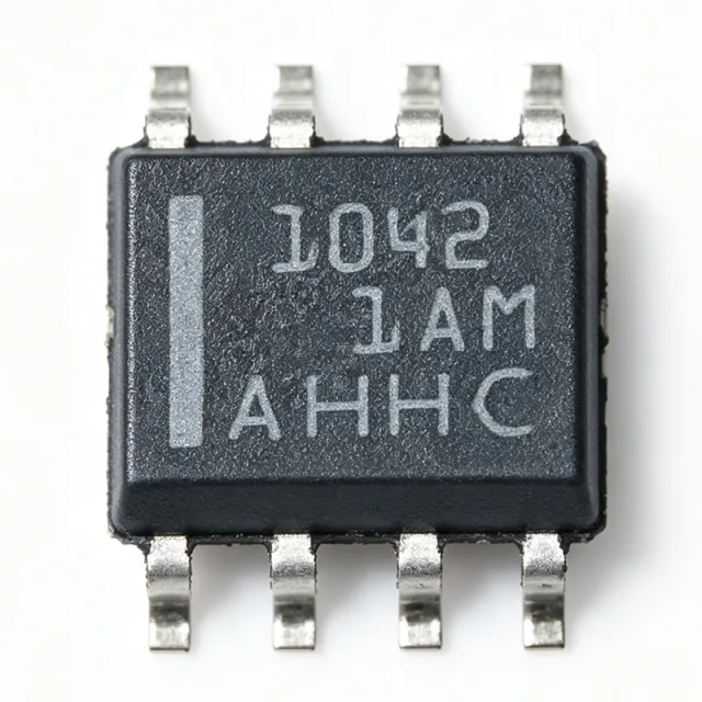
TCAN1042GVDRQ1 - Automotive CAN FD Transceiver | Texas Instruments
TCAN1042GVDRQ1 is an automotive fault-protected CAN transceiver from Texas Instruments, supporting CAN FD data rates up to 5 Mbps with I/O level shifting. It is housed in an 8-pin SOIC (D) package and operates across a temperature range of -55°C to 125°C. A CAN transceiver is a physical layer interface between a CAN controller and the CAN bus twisted-pair wiring. It converts the differential CAN bus signals (CANH/CANL) into single-ended logic levels for the controller, and vice versa. In automotive and industrial networks, the transceiver must handle harsh electrical environments, including voltage transients, ground offsets, and short-circuit conditions, all of which TCAN1042GVDRQ1 is designed to protect against. Key features include fault protection against bus short-circuits and high-voltage transients, I/O level shifting for interfacing with 3.3V or 5V controllers, flexible data-rate operation up to 5 Mbps, and low-power standby mode. The device meets the requirements of ISO 11898-2 for automotive CAN, providing robust communication with a 1/1 driver/receiver configuration and half-duplex operation. Technically, TCAN1042GVDRQ1 integrates a differential driver and receiver, providing differential transmit and receive capability. The I/O level shifting feature allows direct connection to microcontrollers with lower logic levels, eliminating the need for external level translators. Fault protection safeguards the device and bus against short circuits, thermal stress, and voltage surges, ensuring reliable communication in noisy environments. Typical applications include automotive body control modules, gateways, battery management systems, industrial automation, and medical devices where reliable CAN communication is required. The wide operating temperature range and AEC-Q100 qualification (implied by automotive designation) make it suitable for under-hood and harsh environment deployments. During design, ensure proper decoupling capacitors (100 nF and 10 uF) are placed close to the VCC pin to minimize noise, and use the appropriate bus termination resistors (120 ohms) at both ends of the bus. The SOIC-8 package allows compact PCB layouts, but thermal management should be considered for high-temperature environments.

TCAN1044DRQ1 - 8Mbps CAN FD Transceiver, 8-SOIC | Texas Instruments
The Texas Instruments TCAN1044DRQ1 is an automotive-qualified, high-speed Controller Area Network (CAN) transceiver meeting the physical-layer requirements of the ISO 11898-2:2016 standard. It supports both classical CAN and CAN FD (Flexible Data-Rate) networks at data rates up to 8 megabits per second (Mbps), and ships in an 8-pin SOIC (DRB) package with an operating temperature range of -40 C to +125 C. A CAN transceiver is a physical-layer interface IC that bridges a digital CAN protocol controller (typically embedded in a microcontroller) to a differential two-wire CAN bus. The transceiver translates the controller's single-ended TXD/RXD logic signals to the bus's dominant/recessive differential signaling required by ISO 11898-2, while providing bus-side ESD protection, common-mode range, and dominant-time-out fault protection. The TCAN1044-Q1 family sits in the CAN interface IC -> interface IC -> integrated circuit hierarchy and is a foundational building block for in-vehicle networks (IVN). Key features include 8 Mbps CAN FD data-rate support for next-generation vehicle networks, IEC 61000-4-2 ESD protection on bus pins, low-loop delay for propagation-tight networks, and a low-power standby mode with a remote-wake-up wake request via the bus (per the TCAN1044 family datasheet). The device operates from a single 4.5 V to 5.5 V VCC supply, draws typically 50 mA in normal mode, and integrates thermal shutdown plus bus-dominant time-out to prevent network lockup. The TCAN1044DRQ1 architecture uses a high-speed differential driver and a wide-common-mode receiver that exceeds the -2 V to +7 V common-mode range required by ISO 11898-2:2016. Internal level shifting on TXD/RXD allows direct connection to 3.3 V or 5 V microcontrollers without external logic-level translators, and the integrated bus fault protection tolerates -58 V to +58 V transients common in automotive 12 V/24 V systems. Typical applications include automotive body and chassis CAN nodes (BCM, gateway modules), CAN FD powertrain networks, industrial CAN-bus field-bus nodes, and electric-vehicle battery management system (BMS) master/slave communication. The AEC-Q100 Grade 1 qualification makes it appropriate for under-hood and safety-critical vehicle ECUs. When designing with this part, observe the 60 ohm bus termination requirement of ISO 11898-2 and place a 100 nF VCC decoupling capacitor within 2 mm of the supply pin. Avoid routing the CANH/CANL differential pair over splits in reference planes, and use a 120 ohm characteristic-impedance cable/trace geometry. This page synthesizes distributor pricing, drop-in pin-compatible alternatives, and practical PCB design notes for the TCAN1044DRQ1 - information not consolidated in the manufacturer datasheet alone.

TCAN1051-Q1 - Automotive Fault-Protected CAN FD Transceiver | Texas Instruments
TCAN1051-Q1 from Texas Instruments is an automotive fault-protected CAN transceiver with flexible data-rate and sleep mode, meeting ISO 11898-2 (2016) High-Speed CAN physical layer standard. It comes in an 8-pin SOIC package, supporting data rates up to 2 Mbps in CAN FD networks; variants with the G suffix support up to 5 Mbps, while V-suffix versions add a secondary power supply input for I/O voltage. A CAN transceiver is the physical-layer interface between a CAN protocol controller (MCU) and the two-wire differential CAN bus. In the automotive hierarchy, the CAN bus connects ECUs such as engine control, body control, and infotainment modules. The transceiver converts TXD/RXD logic signals from the MCU into differential CANH/CANL signals on the bus and provides bus fault protection. Key features include high on-chip IEC ESD protection, silent mode for reduced power consumption, and AEC-Q100 automotive qualification. The device is designed for harsh automotive environments, with fault protection that withstands bus transients. The flexible data-rate option enables CAN FD networks up to 5 Mbps, making it suitable for modern vehicle architectures that require higher bandwidth. The TCAN1051 family uses a robust physical-layer design with protection diodes and a dominant time-out function, ensuring reliability under bus shorts and high-voltage transients. The device supports both 5 V and (in V variants) 3.3 V I/O reference voltage, allowing direct interface with low-voltage microcontrollers. Typical applications include automotive body control modules, battery management systems, powertrain control, and industrial automation networks. The TCAN1051-Q1 is also widely used in diagnostics (OBD-II) and infotainment systems. Design consideration: ensure proper termination (120 ohm) and place TVS diodes and bus filtering capacitors close to the on-board connectors to prevent transient events from propagating into the PCB.

TCAN1051DRBRQ1 - Automotive CAN FD Transceiver | TI
The Texas Instruments TCAN1051DRBRQ1 is an automotive fault-protected CAN transceiver with CAN FD flexible data-rate support up to 2 Mbps, integrated sleep mode, and a 5 V supply, housed in an 8-pin VSON (DRB) 3x3 mm package rated from -55C to +125C. A CAN (Controller Area Network) transceiver is the physical-layer interface IC that converts the logic-level TXD and RXD signals of a CAN controller into the differential CANH and CANL bus signals defined by ISO 11898. Within the vehicle networking hierarchy, the transceiver sits between the MCU/CAN controller and the twisted-pair bus, providing dominant/recessive signaling, bus fault protection, and low-power standby or sleep behavior for networked electronic control units. Key features include automotive AEC-Q100 qualification, fault protection on the CAN bus pins (protection against faults to battery, ground, and overvoltage per the TI TCAN1051-Q1 product page), CAN FD flexible data-rate support up to 2 Mbps, and a sleep mode that reduces quiescent current for always-on vehicle networks. The -55C to +125C operating range supports under-hood and chassis deployments. The device implements a half-duplex differential physical layer with integrated receiver and driver stages. Internal protection circuitry clamps bus-pin transients and survives DC fault conditions on CANH and CANL, reducing the need for extensive external TVS components in harsh 12 V and 24 V vehicle power environments. Typical applications include body control modules, gateways, ADAS sensor clusters, battery management systems, and industrial CAN networks requiring robust fault tolerance and low standby power. Design consideration: confirm the sleep-mode wake behavior and bus biasing scheme against the TI datasheet, and verify that the 3x3 mm VSON thermal pad is well soldered to ground for transient robustness. This page synthesizes verified distributor listings, drop-in same-family alternatives, and design guidance not consolidated in the manufacturer datasheet.
TCAN1472-Q1 - Automotive CAN SIC Transceiver, 8Mbps, 8-SOIC | TI
The Texas Instruments TCAN1472-Q1 is an automotive-grade, fault-protected CAN FD transceiver with Signal Improvement Capability (SIC) that supports classical CAN and CAN FD up to 8 Mbps, available in an 8-pin SOIC (D) package with industry-standard pin-out. It is qualified to AEC-Q100, listed as Functional Safety-Capable, and is designed to meet the physical-layer requirements of ISO 11898-2:2024 Annex A (CAN SIC). A CAN (Controller Area Network) transceiver is the physical-layer interface between a CAN protocol controller (typically an MCU or ASIC) and the differential CAN bus wiring. It converts the controller's TX/RX logic-level signals to the bus's dominant/recessive differential voltages and adds bus-side protection, fault detection, and EMC filtering. SIC is an optional extension layer that actively reshapes the bus waveform to reduce ringing on long stubs and high-speed topologies, allowing faster bit rates (up to 8 Mbps with CAN FD) on networks that previously had to slow down for signal integrity reasons. Key features of the TCAN1472-Q1 include: support for classical CAN and CAN FD up to 8 Mbps with active SIC; ±58 V (typ.) fault-protected CAN bus pins; IEC 61000-4-2 ESD rating of ±8 kV contact / ±15 kV air on bus pins; low-current standby mode with remote wake-up via bus; and an operating voltage range of 4.5 V to 28 V (load-dump tolerant up to 40 V). 'V'-suffix variants (e.g. TCAN1472VDRQ1, TCAN1472VDFFRQ1) include a VIO logic-level supply pin so the device can interface directly with 1.8 V / 2.5 V / 3.3 V MCUs without external level shifters. The device integrates a 3.3 V / 5 V tolerant reference output, thermal shutdown, driver-dominant time-out, and under-voltage lockout on both VCC and VIO. Its bus-side hardware meets ISO 11898-2:2024 Annex A (SIC), ISO 11898-2:2016, and SAE J2284, making it drop-in compatible with existing 8-pin CAN FD footprints such as TCAN1042-Q1 and TCAN1044A-Q1 while adding the SIC waveform improvement stage. Typical applications include automotive body and chassis ECUs (BCM, gateway, HVAC, lighting), ADAS sensor fusion ECUs, xEV battery-management and powertrain controllers, industrial CAN networks with long stub lengths, and any automotive CAN FD node that needs to coexist with classical CAN on the same bus. The wide supply range also makes the part well suited for 12 V and 24 V truck and off-road CAN bus systems. When designing with the TCAN1472-Q1, place a 100 nF decoupling capacitor as close as possible to VCC and (on V-suffix parts) VIO, and a 4.7 µF or larger bulk capacitor on the bus-side CAN supply. On long-stub networks, leave SIC enabled to suppress reflections; on point-to-point links SIC can be turned off for the lowest loop delay. Always verify that the chosen package thermal pad layout matches the 8-pin SOIC land pattern. This page synthesises TI datasheet parameters, distributor pricing tiers, and drop-in alternatives in the same 8-SOIC footprint - information not all collected on a single manufacturer page.

TCAN334DCNR - 3.3V CAN FD Transceiver, SOT-23-8 | Texas Instruments
The Texas Instruments TCAN334DCNR is a 3.3-V Controller Area Network (CAN) transceiver supporting CAN FD (Flexible Data Rate) up to 1 Mbps, housed in an 8-pin SOT-23 (DCN) package. Designed for ISO 11898-1 High-Speed CAN physical layer compliance, it integrates a 1/1 (one transmit, one receive) transceiver half between a CAN protocol controller and the physical bus, with low power Shutdown and Standby modes for battery-powered applications. A CAN transceiver is a physical-layer interface IC that converts the differential digital signals of a CAN protocol controller into the robust, fault-tolerant differential signaling required on the automotive or industrial CAN bus. Within the broader hierarchy, a CAN transceiver sits below the CAN controller (typically integrated in an MCU) and above the physical twisted-pair bus; it belongs to the Interface ICs > Networking transceivers category and is essential for in-vehicle networking (CAN, CAN FD), industrial automation (CANopen, DeviceNet), and any distributed control system requiring reliable multi-node communication. Key features include 3.3-V single-supply operation compatible with 3.3-V MCUs (no level shifter required), ultra-low current consumption in Shutdown/Standby modes, integrated bus dominant time-out protection, thermal shutdown, and an internal slope-control / driver output that meets the ISO 11898-2 (High-Speed CAN) requirements. Logic-side inputs are TTL-compatible and tolerate 5-V MCU rails. The TCAN334DCNR uses TI's BiCMOS process, allowing the high-voltage bus side (up to +-18-V fault on CANH/CANL) to coexist with the low-voltage 3.3-V digital core. Loop-delay symmetry is optimized for CAN FD frames with payload bit rates beyond 1 Mbps on the data phase, ensuring robust arbitration-to-data transitions. Typical applications include automotive body electronics (door modules, HVAC, seat controllers), industrial sensor networks, building automation, battery management (BMS) slave-node communication, and any 3.3-V MCU system requiring a compact CAN physical interface. When designing with this device, ensure the CAN bus termination (typically 120 ohms at each bus end) is correct, and route the CANH/CANL traces as a 100-ohm differential pair on the PCB. The 8-pin SOT-23 footprint gives strong thermal coupling for a small package, allowing sustained high-bus-traffic operation without exceeding junction ratings. This page synthesizes distributor pricing, drop-in alternatives, and practical design notes not found in the manufacturer datasheet alone, supporting faster design decisions for embedded engineers.
TCAN3403-Q1 - 3.3V Automotive CAN FD Transceiver | TI
The Texas Instruments TCAN3403-Q1 is an automotive-grade 3.3 V Controller Area Network (CAN) Flexible-Data-Rate (FD) transceiver with flexible I/O and standby mode, available in 8-pin SOIC (D) and 8-pin SON (DRB) packages. It supports data rates up to 5 Mbps (CAN FD) and is compliant with ISO 11898-2:2016 physical-layer requirements, including ±58 V bus fault protection for 12 V and 24 V battery systems. Internal logic-level translation through the VIO pin (1.7 V to 5.5 V) allows direct interface to 1.8 V, 2.5 V, or 3.3 V MCUs without an external level shifter. A CAN transceiver (also called a CAN physical-layer or CAN PHY) is the analog interface IC that sits between a digital CAN protocol controller (typically inside an MCU) and the differential CANH/CANL bus wires. It converts the controller's transmit (TXD) digital stream into a balanced differential signal on the bus and vice versa, while providing dominant/common-mode biasing, ESD protection, bus-fault survival, and optional low-power modes. CAN FD extends classic CAN by increasing payload size (64 bytes) and bit rate (up to 5 Mbps in the data phase), enabling higher bandwidth for automotive body, chassis, and powertrain networks; the TCAN3403-Q1 operates seamlessly on mixed classic CAN and CAN FD networks. Key features of the TCAN3403-Q1 include AEC-Q100 Grade 1 qualification for automotive use, ±58 V bus standoff (versus typical ±40 V parts), low-loop delay for FD arbitration, thermal-shutdown protection, and a standby mode with remote-wake request via the bus (per ISO 11898-2:2016). The 3.3 V single-supply operation eliminates the 5 V LDO that older 5 V transceivers required, reducing BOM cost and PCB area by roughly 10-30 mm². The device uses a symmetric differential driver architecture with controlled edge rates to minimize EMI and reflections on unterminated stubs. Integrated protection includes undervoltage lockout on both VCC and VIO, TXD dominant-timeout to prevent bus lockup, hot-plug support, and ±25 kV HBM / ±12 kV IEC 61000-4-2 contact discharge ESD on the bus pins. Typical automotive applications include body-control modules (BCM), gateway ECUs, infotainment domain controllers, ADAS sensor ECUs, and industrial CAN-FD nodes needing automotive-grade qualification. The wide bus-fault range also makes it suitable for 24 V truck and off-road machinery CAN buses where legacy 5 V parts would fail. Designers should add a 100 nF decoupling cap on VCC and VIO placed within 2 mm of the pins, and a common-mode choke plus split termination (60 Ω + 60 Ω with 4.7 nF to ground) on the bus side for IEC 61000-4-2 ESD compliance and best EMI performance. The STB pin enables standby mode (~15 µA ICC), so connect it to a GPIO for software-controlled sleep. This page synthesizes distributor pricing, drop-in alternatives, and practical design notes not found in the manufacturer datasheet.
TCAN3404-Q1 - Automotive 3.3V CAN FD Transceiver | Texas Instruments
The Texas Instruments TCAN3404-Q1 is an automotive-qualified 3.3V CAN flexible-data-rate (CAN FD) transceiver that supports data rates up to 8 Mbps and is housed in an 8-pin TSOT-23 (DDF) package. The device integrates ±58V bus fault protection and is compliant with the ISO 11898-2:2016 high-speed CAN physical layer specification. It is AEC-Q100 qualified for automotive applications and supports both low-power standby mode (controlled via the STB pin) and an ultra-low-power shutdown mode (controlled via the SHDN pin). A CAN FD transceiver, also called a CAN physical-layer (PHY) device, is the interface between a digital CAN controller (or microcontroller with integrated CAN MAC) and the differential CAN bus wires. It converts the controller's transmit (TXD) and receive (RXD) single-ended logic signals into differential bus voltages (CANH, CANL), and provides bus arbitration, fault protection, and ESD handling for the harsh automotive electrical environment. The TCAN3404-Q1 belongs to the broader category hierarchy of: CAN transceiver → CAN interface IC → serial interface IC → wired connectivity IC → interface & connectivity semiconductor. The 3.3V (rather than 5V) supply rail reduces power loss in modern automotive MCU domains. Key features include ±58V bus fault tolerance (industry-leading for the 8-pin TSOT-23 form factor), ±25V common-mode range on CANH/CANL, 8 kV HBM ESD protection on bus pins, low-loop delay to support 8 Mbps CAN FD frames, and ultra-low-power shutdown current. Internal pull-down resistors on STB and SHDN default the device to safe operating states if pins are left floating. The TSOT-23-8 package measures 2.9 mm × 1.6 mm and is well suited for space-constrained body electronics and zonal ECU modules. Architecturally, the TCAN3404-Q1 uses a single 3.3V supply rail, eliminating the need for an external charge pump or 5V regulator that legacy 5V CAN transceivers sometimes require. The transmitter and receiver share a common-mode reference and slope-control circuitry, allowing fast bit transitions while minimizing EMI on unshielded twisted-pair automotive harnesses. The device is designed for robust coexistence on mixed 3.3V/5V CAN networks, with a recessive bias that minimizes error frames during arbitration. Typical applications include automotive body control modules, gateway ECUs, ADAS sensor CAN-FD links, battery management system (BMS) communication buses, and infotainment CAN backbones. It is also used in industrial CAN-FD nodes and heavy-truck J1939 networks where ±58V load-dump survival is required. The shutdown mode is particularly useful in battery-powered systems that need to enter sleep states with the bus still biased. Designers should pair the TCAN3404-Q1 with a 3.3V CAN-capable MCU (such as TI's TMS570 or C2000 families) and provide a common-mode choke plus split termination on the bus to maximize radiated-emissions margin. Care must be taken not to leave SHDN floating in mission-critical designs; tying it to logic high enables ultra-low-power mode when the ECU shuts down. This page aggregates distributor stock, verified drop-in replacement MPNs (including the closely-related TCAN3403-Q1 and TCAN3413-Q1), and engineering design notes that supplement the manufacturer datasheet with PCB-layout, ESD, and mixed-voltage coexistence guidance.
TCAN3413 - 3.3V CAN FD Transceiver, ±58V Bus Fault, SOIC-8 | TI
The Texas Instruments TCAN3413 is a 3.3-V Controller Area Network Flexible Data-rate (CAN FD) transceiver in an 8-pin SOIC (D) package with ±58-V bus fault protection, ISO 11898-2:2016 compliance, and certified EMC operation up to 5 Mbps. It includes internal logic-level translation via the VIO pin that allows the I/O side to interface directly to 1.8-V, 2.5-V, or 3.3-V logic, eliminating the need for an external level shifter on multi-voltage MCUs. The device supports a low-power standby mode with wake-up over CAN that conforms to the ISO 11898-2:2016 wake-up pattern (WUP), making it well suited to automotive body and industrial remote-IO applications that must stay quiescent until bus activity resumes. A CAN bus is a differential, multi-drop vehicle and industrial field bus originally specified by Bosch and standardized by ISO 11898; CAN FD extends classical CAN from 1 Mbps to 5 Mbps and increases payload from 8 bytes to 64 bytes, while the physical-layer chip (the transceiver) adapts digital logic to the differential bus and protects downstream devices from the harsh bus-side environment. The TCAN3413 belongs to the TI CAN physical-layer IC family, which sits between the protocol controller (in the MCU) and the differential bus lines, and is widely deployed alongside TCAN3414 in the same product family. The device is a direct successor to legacy 3.3-V CAN transceivers and provides higher bus-fault tolerance, robust ESD protection on the bus pins, and more flexible power-saving options. Typical use cases include automotive body electronics, industrial control CAN nodes, building-automation sensors, and telecom base-station housekeeping buses. When designing with this part, ensure the VIO supply matches the MCU logic level and that bus termination follows ISO 11898-2:2016 guidance, as improper stub length and missing 120 ohm terminations are the leading cause of bus error frames. This page synthesizes distributor pricing, drop-in alternatives from the same TI CAN family, and practical design notes not found in the manufacturer datasheet.
TCAN3414 - 3.3V CAN FD Transceiver, 5Mbps, ±58V Bus Fault | Texas Instruments
The Texas Instruments TCAN3414 is a 3.3-V Controller Area Network Flexible Data Rate (CAN FD) transceiver with standby mode, supporting data rates up to 5 Mbps and providing ±58-V bus fault protection. Housed in 8-pin SOIC (D) and 8-pin SON (DRB) packages, it is designed for industrial, automotive, and building-automation networks that need robust communication in electrically harsh environments. A CAN transceiver is the physical-layer interface between a CAN protocol controller (typically a microcontroller's CAN module or an external CAN controller) and the differential CAN bus. It converts the controller's digital transmit/receive signals into the ISO 11898-2:2016 compliant differential bus levels, while providing ESD protection, common-mode rejection, and bus fault tolerance. Within the broader hierarchy, a CAN transceiver sits below the CAN controller and above the physical wiring harness, and is itself a type of line driver / interface IC in the Interface > Interface ICs category. Key features include certified electromagnetic compatibility (EMC) for classical CAN and CAN FD up to 5 Mbps, ±58-V bus fault protection on the CANH/CANL pins, ±30-V common-mode range, and ±8-kV HBM ESD protection per IEC 61000-4-2 contact discharge on bus pins. The 1.7-V to 3.6-V IO range allows direct interfacing with 1.8-V, 2.5-V, 3.3-V, and 5-V microcontrollers without level shifters. A standby mode (via the STB pin) reduces quiescent current for low-power system sleep states. From an architecture standpoint, the TCAN3414 integrates a high-speed differential line driver, a differential comparator receiver, internal slope control for reduced EMI, and thermal-shutdown protection. The driver exhibits typical loop delay under 200 ns, allowing robust CAN FD performance at 2 Mbps and 5 Mbps. The internal protection circuitry clamps inductive transients on the bus, and the device meets the GIFT/ICT compliant IEC 62228-3 and IEC 61000-4-2 standards for ESD on bus pins. This combination makes the TCAN3414 a robust drop-in upgrade for older 3.3-V CAN transceivers such as the SN65HVD233/234/TCAN332 families. Typical applications include industrial CAN nodes (PLC modules, motor drives, sensors), building-automation HVAC controllers, battery-management system (BMS) communication in 48-V mild-hybrid and energy-storage systems, automotive body and infotainment ECUs, and any embedded design that needs certified EMC and high bus-fault tolerance on a 3.3-V rail. The ±58-V bus fault protection eliminates the need for external TVS diodes in most 12-V and 24-V industrial systems, simplifying BOM and reducing PCB area. When designing with this device, place the VIO/VCC decoupling capacitors as close as possible to the device pins and use a 100-nF X7R ceramic plus a 1-µF bulk capacitor. Ensure the CAN bus is terminated with 120-Ω resistors at each end of the bus (per ISO 11898-2), and keep the CANH/CANL traces as a tightly coupled differential pair to minimize EMI emissions. This page synthesizes distributor pricing, drop-in alternatives, application guidance, and design notes that go beyond what the manufacturer datasheet alone provides. XAIPART cross-references verified stock from authorized distributors and pairs it with parametric comparison tables to help engineers select the correct 3.3-V CAN FD transceiver for industrial and automotive designs.

TCAN4572-Q1 - Automotive CAN FD Controller + SIC Transceiver | TI
The Texas Instruments TCAN4572-Q1 is an automotive-grade CAN FD controller with an integrated CAN Signal Improvement Capable (SIC) transceiver, housed in a VQFN-24 package. It combines an ISO 11898-1:2015 compliant CAN FD protocol controller with an ISO 11898-2:2016 compliant physical layer transceiver, supporting data rates up to 8 Mbps with SIC enabled for improved signal integrity on long or star-topology bus networks. A CAN FD (Controller Area Network Flexible Data-Rate) controller with integrated transceiver is a system-on-chip that combines a CAN protocol engine and a physical layer transceiver in one device. The protocol controller manages message framing, arbitration, and error handling per the ISO 11898-1 standard, while the transceiver converts digital logic levels to the differential CANH/CANL bus signals per ISO 11898-2. By integrating both blocks, the TCAN4572-Q1 reduces PCB area, BOM count, and host MCU CAN peripheral requirements, placing it within the broader hierarchy of automotive interface IC > CAN interface > CAN FD transceiver/controller > in-vehicle networking IC. Key features include support for classic CAN and CAN FD frames, an SPI interface to the host microcontroller, AEC-Q100 qualification for automotive applications, and SIC (Signal Improvement Capability) for cleaner signal edges on complex topologies. The device operates over a wide supply range suitable for 12V automotive battery rails and includes thermal shutdown, bus dominant time-out, and undervoltage protection. The architecture pairs a dedicated CAN FD controller core with a low-emission differential transceiver. By performing in-situ signal conditioning via SIC, the TCAN4572-Q1 allows designers to deploy CAN FD networks across unshielded cable, mixed topologies, or nodes with significant stub lengths without compromising the bit-time budget. Typical applications include automotive body and chassis ECUs, ADAS sensor networks, battery management system (BMS) communication in electric vehicles, industrial CAN FD gateways, and CAN FD Light systems. The integrated MCU interface simplifies bring-up across zonal architectures where the host processor may lack an on-chip CAN FD peripheral. Designers must evaluate bus topology termination, stub length, and SIC enable/disable timing relative to network jitter budgets. The SPI clock and chip-select routing should be kept short to avoid protocol-controller timing violations during bus error interrupts. This page synthesizes distributor availability, drop-in alternative candidates, and practical design guidance drawn from the Texas Instruments TCAN4572-Q1 datasheet in a single product brief not found on the manufacturer page or distributor listings alone.
TCAN6062-Q1 - CAN XL Transceiver, AEC-Q100, SOIC-8 | TI
The Texas Instruments TCAN6062-Q1 is an automotive-grade, high-speed Controller Area Network (CAN) transceiver that meets the physical layer requirements of the ISO 11898-2:2024 Annex A (CAN XL) specification, housed in an 8-pin SOIC (D) package. Key parameters include CAN XL data-rate support up to 20 Mbps, integrated Signal Improvement Capability (SIC) mode, and PWM decoding on the TXD pin for FAST TX/FAST RX operation. A CAN transceiver is a physical-layer interface IC that converts the differential CAN bus signals (CANH, CANL) into the single-ended TXD/RXD logic levels required by a host microcontroller or CAN controller. It sits in the hierarchy bus transceiver -> bus interface IC -> interface IC -> semiconductor, providing galvanic isolation, level shifting, bus dominant/recessive arbitration, and EMC/ESD protection for the in-vehicle network. Modern CAN XL extends classical CAN and CAN FD by adding a higher data-rate payload channel while preserving backward compatibility with ISO 11898-2. Key features include an integrated standby mode for low-power sleep current, ±8 kV IEC 61000-4-2 ESD protection on the bus pins, ±58 V bus fault protection, and AEC-Q100 Grade 1 qualification (–40 °C to +125 °C ambient). The TCAN6062-Q1 also supports PWM-decoded signaling on TXD, enabling the SIC mode to actively reduce signal ringing during dominant-to-recessive transitions, which is critical for reliable multi-drop CAN XL networks at high data rates. The device architecture pairs a high-speed differential driver/receiver pair with an internal logic core that monitors TXD and decodes PWM-coded commands to switch between normal, FAST TX, FAST RX, SIC, and standby states. Compared with legacy CAN FD transceivers (e.g. TCAN1044A-Q1), the TCAN6062-Q1 adds CAN XL PHY support and the signal-conditioning features required for ISO 11898-2:2024 Annex A compliance, while remaining pin-compatible to 8-pin SOIC footprints used by prior TCAN families. Typical applications include automotive CAN XL backbone and zone-architecture networks, ADAS sensor ECUs (radar, lidar, camera), powertrain and chassis CAN nodes, body-domain controllers, and industrial CAN networks migrating from CAN FD to CAN XL. A key design consideration: ensure the bus termination (typically 120 Ω at each end of the CAN XL backbone, with SIC transceivers often allowing split termination) is sized according to the cable DC resistance and number of in-line stubs. STB pin logic levels must respect the wake/sleep timing in the datasheet to avoid bus contention on cold-start. This page synthesizes manufacturer specifications, distributor availability, AEC-Q100 compliance signals, and same-package cross-reference MPNs (TCAN1044A-Q1, TCAN1472-Q1) into a single engineering reference not duplicated on the TI datasheet alone.

TDA19989BET/C1,557 - 150MHz HDMI 1.4 TX | NXP Semiconductors
The NXP Semiconductors TDA19989BET/C1,557 is a 150 MHz pixel rate HDMI 1.4 transmitter video IC with 3 x 8-bit video inputs, HDCP 1.3 content protection, and CEC support, housed in a 64-pin TFBGA (4.5 x 4.5 mm) package. A video transmitter IC (also called an HDMI transmitter or video encoder) is an interface IC that converts a parallel digital video stream, such as ITU-R BT.656 or RGB data, into a serial TMDS (Transition Minimized Differential Signaling) signal compliant with HDMI or DVI standards. In the signal-chain hierarchy, it sits between a graphics source or video processor and the HDMI physical connector, performing serialization, encoding, and content-protection tasks required by the CEA-861B, HDMI 1.3a/1.4, and DVI 1.0 specifications. Key features include support for CEA-861B, DVI 1.0, HDMI v1.3a and HDMI 1.4 formats, HDCP 1.3 for encrypted content delivery, an I2C control interface, and ITU656 video input compatibility. The 150 MHz pixel rate supports video resolutions up to 1080p, while the 64-TFBGA footprint keeps board area to approximately 20.25 square millimeters for space-constrained designs. Architecturally, the TDA19989B family integrates TMDS serializers, an HDCP cipher engine, an audio return and CEC block, and flexible input multiplexing for three 8-bit video buses. The I2C register interface allows a host microcontroller to configure timing, audio, and protection parameters. The C/1,557 ordering suffix identifies the standard-rated commercial temperature grade in tape-and-reel packaging. Typical applications include set-top boxes, digital televisions and monitors, AV receivers, video projectors, and embedded systems that must output HDMI while processing ITU656 or RGB video internally. When designing with this device, provide a stable low-jitter TMDS reference clock and follow NXP layout guidance for 100-ohm differential impedance routing on the HDMI lanes; HDCP key handling also requires attention to firmware security practices. This page synthesizes distributor inventory data, drop-in alternative guidance, and practical design notes not found in the manufacturer datasheet alone.
TDA19989BET/C1551 - 150MHz HDMI 1.4 Transmitter | NXP
The NXP TDA19989BET/C1551 is a 150 MHz pixel rate HDMI 1.4 transmitter IC with HDCP 1.3 content protection and CEC support, housed in a 64-ball TFBGA (4.5 x 4.5 mm) package. It accepts parallel digital video (RGB/YCbCr, ITU656) and serializes it for HDMI or DVI output at pixel rates up to 150 MHz. An HDMI transmitter is a video interface IC that converts parallel or digital video bus data into the TMDS (Transition Minimized Differential Signaling) serial stream defined by the HDMI and DVI standards. Within the system hierarchy, it sits in the video signal chain between a graphics source (SoC, FPGA, or video processor) and the physical HDMI connector, and belongs to the broader class of interface ICs and video processing ICs. Key features include the 150 MHz pixel clock supporting 1080p60 video, compliance with CEA-861B, DVI 1.0, and HDMI v1.3a signaling with HDMI 1.4 capability, and integrated HDCP 1.3 cipher engine for protected content. An I2C host interface programs registers, controls the HDCP state machine, and reads EDID from the sink via DDC. CEC support enables consumer electronics control channel communication over the HDMI cable. Architecturally, the TDA19989 family combines input video formatting, TMDS serialization, audio embedding, infoframe generation, and HDCP encryption in a single low-power CMOS die. The 3 x 8-bit video input bus accepts RGB or YCbCr formats, while audio is accepted via I2S or S/PDIF-style inputs and multiplexed into the TMDS stream. Typical applications include set-top boxes, Blu-ray/DVD players, digital media adapters, automotive infotainment head units, and embedded boards with HDMI display outputs. Its compact 4.5 mm BGA suits space-constrained consumer and industrial designs. Designers should note that HDCP license agreements govern use of the cipher, and that the 64-TFBGA requires controlled-impedance TMDS routing on the PCB. Note the part is listed as obsolete by some sources, so verify lifecycle for new designs. This page synthesizes distributor pricing, same-family drop-in alternatives, and practical design notes not found in the manufacturer datasheet.

TDA51S-41HC - 5kVrms Isolator w/ DC-DC 150Mbps | MORNSUN
The MORNSUN TDA51S-41HC is a high-performance reinforced digital isolator with an integrated isolated DC-DC converter, providing 5000Vrms isolation, 150Mbps signal rate, and 150kV/us common-mode transient immunity in a 16-pin SOIC-16-300mil (wide-body) package. It operates from -40C to +125C, with a primary-side supply of 3.13V to 3.56V (3.3V nominal) and a secondary-side supply supporting up to 5.5V, and carries a UL1577-based 5000Vrms isolation rating. An isolated data transceiver with an integrated isolated power supply is a device that combines galvanic signal isolation and an on-chip (or on-module) isolated power source in one package. In the power-management hierarchy, it sits above standalone digital isolators, which require a separate isolated DC-DC converter or power module to energize the isolated side. By eliminating that external isolated supply, this device class delivers a complete, small-form-factor isolation solution with fewer components, lower BOM cost, and reduced layout risk. Key features of the TDA51S-41HC include the integrated isolated DC-DC converter, which removes the need for a separate isolated power supply; 150Mbps data rate for high-speed serial links; 150kV/us CMTI for immunity against fast switching transients typical of SiC and IGBT power stages; 5000Vrms reinforced isolation per UL1577; and a wide -40C to +125C industrial operating range. The device provides three forward-direction and one reverse-direction channel, with a fail-safe option: if the input signal is lost, the default output is low for devices with the H suffix, which matches the 41HC suffix in this MPN. The integrated power architecture uses on-chip transformer-based isolation for both signal and power transfer, keeping the total solution footprint small while maintaining reinforced-insulation creepage and clearance in the SOIC-16-300mil wide body. Typical applications include isolated RS-485/fieldbus nodes in industrial automation, isolated power and communication for IGBT/SiC gate-drive circuits, battery management systems, and PLC I/O modules. The combination of signal and power isolation is especially valuable where board space or single-supply constraints make a discrete isolated supply impractical. Design consideration: verify that the integrated DC-DC output power budget covers the isolated-side load; the converter is intended to supply the isolated-side transceiver and light external loads, not full power rails. This page synthesizes distributor data, the MORNSUN datasheet, drop-in family alternatives, and practical design notes not found on the manufacturer product page.
TDA51S485HC - Isolated RS-485 Transceiver 500kbps | MORNSUN
The MORNSUN TDA51S485HC is an isolated, half-duplex enhanced RS-485/RS-422 transceiver with integrated signal isolation, fully compliant with the TIA/EIA-485-A standard, supporting data rates up to 500 kbps in a 16-pin SOIC-16 (300 mil) package. An isolated RS-485 transceiver is a communication interface IC that combines a differential line driver and receiver with galvanic isolation between the logic side and the bus side. Isolation is a critical layer in industrial system hierarchy: within power management and interface electronics, it breaks ground loops, blocks common-mode transients, and protects low-voltage controllers from high-voltage faults on long cable runs in factories and buildings. Key features of the TDA51S485HC include full TIA/EIA-485-A compliance, half-duplex operation on a single twisted pair, data transmission up to 500 kbps, and an integrated fail-safe circuit. The fail-safe function guarantees a defined receiver output state when the bus is idle, shorted, or open, eliminating false characters caused by undriven bus conditions - a common problem in legacy RS-485 networks that otherwise requires external bias resistors. The enhanced transceiver architecture integrates the isolation barrier in a compact SOIC-16-300mil body, reducing board area compared to discrete optocoupler-plus-transceiver designs. It is engineered for harsh industrial environments where robust differential signaling, noise immunity, and long-distance communication over twisted-pair cable are required. Typical applications include industrial automation and PLC networks, building control and HVAC systems, motor control and inverter communication buses, energy metering, and security or access-control systems that communicate over RS-485 fieldbus segments. A key design consideration is bus termination and biasing: even with the internal fail-safe circuit, verify that your network topology, node count, and cable length remain within RS-485 loading and 500 kbps timing budgets; add 120-ohm termination at both cable ends for long runs. This page synthesizes distributor pricing, stock data, drop-in alternative information, and practical design notes not found in the manufacturer datasheet alone.
TDA51SCANHC - 5kV Isolated CAN Transceiver 1Mbps | MORNSUN
The MORNSUN TDA51SCANHC is an isolated CAN bus transceiver module with an integrated 5 V isolated power supply, compliant with the ISO11898-2 standard, capable of data rates up to 1 Mbps in a 16-pin SOIC (SOIC-16-300mil, 7.50 mm width) package. An isolated CAN transceiver is an interface IC that provides galvanic isolation between a CAN protocol controller and the physical two-wire CAN bus. Isolation breaks ground loops, protects low-voltage circuitry from common-mode transients, and is essential where nodes span large ground potential differences. Within the signal-chain hierarchy, the TDA51SCANHC belongs to the isolated interface family: transceiver -> bus transceiver -> isolated CAN transceiver -> isolation and interface module. Key features include 5000 VDC galvanic isolation, a common-mode transient immunity of 150 kV/us, and an integrated, efficient 5 V isolated power output that eliminates the need for a separate isolated DC-DC converter on the bus side. The device provides differential transmit and receive capability between the CANH/CANL physical bus and the protocol controller, and it operates across the full -40C to +125C industrial-extended temperature range. A notable protection feature is the TXD dominant time-out function: if a hardware or software fault forces the TXD pin permanently low, the built-in dominant time-out timer prevents the bus from being blocked in a permanent dominant state, safeguarding network availability. Typical applications include industrial fieldbus nodes (Profibus/CANopen gateways), battery management systems, motor-drive control networks, building automation, and medical equipment where isolation between the controller domain and the bus is mandated by safety or robustness requirements. Design consideration: because the part integrates an isolated 5 V power stage, PCB layout must respect the creepage and clearance distances across the isolation barrier defined for the SOIC-16-300mil package, and the integrated power output should be decoupled per the manufacturer datasheet recommendations. This page synthesizes distributor pricing, availability data, family drop-in alternatives, and practical design notes not found in the manufacturer datasheet alone.

TDA8029HL/C207 - Smart Card Reader IC, 5V, LQFP-32 | NXP
The NXP TDA8029HL/C207 is a complete single-chip, low-power, low-cost, robust smart card reader IC supplied in a 32-pin LQFP (7x7 mm) package. It supports ISO 7816-3 and EMV 4.x smart cards and integrates a DC-DC converter capable of operating from a wide supply range, plus a precision card-supply supervisor with spike-killing and power-on reset. The device targets portable POS terminals, set-top box conditional-access modules, identification readers, and SIM/SAM interface designs. Key specifications include operation from a 3 V to 6 V host supply (with 5 V tolerance on the host interface), an on-chip DC-DC converter that can be configured as a doubler, tripler, or follower to generate the card VCC (typically 1.8 V, 3 V or 5 V), card-clock division ratios from 1 to 16, support for synchronous cards (up to 10.8 ETU for the C207 variant), and ISO UART handling with automatic CRCI/LRC computation on T=0 and T=1 protocols. A smart card interface IC (also called a contact smart card reader or ISO 7816 interface) sits between a host microcontroller and a contact-based smart card, providing level shifting, ESD protection, card-presence detection, clock generation and data framing. The TDA8029 family belongs to NXP's smart-card interface portfolio and is widely used in payment terminals, government/eID readers and telecom SIM sockets, forming a dedicated bridge between the secure card world and a general-purpose MCU. The architecture combines an 8-bit parallel host interface with internal FIFOs, on-chip voltage generation and supervision, and dedicated active-low card detect / CMDVKO logic so that the host MCU only has to issue high-level commands. Compared to discrete implementations built from a LDO plus discrete transceivers, the TDA8029HL integrates protection, signal-conditioning and the entire ISO 7816 protocol engine on one die, reducing BOM count and PCB area for compact portable readers. Typical applications include EMV contactless/contact payment terminals, government and healthcare eID document readers, set-top box conditional-access smart cards, USB token readers and PC-linked reader dongles, and industrial access-control terminals. The wide supply range and low standby current make it particularly attractive for battery-powered handheld POS. Designers should pay attention to the decoupling network on the card side (typically 100 nF + 220 nF) and to the chosen step-up/step-down topology - the C207 variant supports synchronous card timing at 10.8 ETU which is mandatory for some payment cards. The host-side software must drive the dedicated power-down mode to achieve the lowest quiescent current when no card is present. This page synthesises authoritative datasheet data, current distributor pricing, drop-in part numbers within the TDA8029 family and cross-vendor equivalents, plus practical design notes that go beyond the manufacturer datasheet alone.

TDC1000QPWRQ1 - Automotive Ultrasonic AFE | Texas Instruments
The TDC1000QPWRQ1 is an automotive-grade ultrasonic sensing analog front end (AFE) from Texas Instruments, designed for level and concentration sensing applications. It integrates a complete signal chain for ultrasonic transducers, including a programmable transmit pulse generator, a low-noise receive amplifier, and a time-to-digital converter (TDC) that measures time-of-flight with high resolution. The device operates over a wide supply range and is specified for the automotive temperature range of -40°C to 125°C, making it suitable for harsh environments. An ultrasonic sensing analog front end is a specialized integrated circuit that interfaces between a microcontroller and an ultrasonic transducer. It generates the excitation pulses to drive the transducer, amplifies the returning echo signal, and converts the time-of-flight into a digital value. This enables precise distance, level, or flow measurements. The TDC1000-Q1 belongs to the family of ultrasonic sensing AFEs, which are part of the broader category of sensor signal conditioning ICs within the analog front end product group. Key features of the TDC1000QPWRQ1 include a programmable transmit frequency up to 1 MHz, a receive amplifier with adjustable gain, and a time-to-digital converter with a resolution of 10 ps. It supports multiple transducer configurations and includes an internal temperature sensor for compensation. The device is AEC-Q100 qualified for automotive applications, ensuring reliability under extreme conditions. Technically, the TDC1000-Q1 uses a time-to-digital conversion architecture that measures the round-trip time of an ultrasonic pulse. This approach provides high accuracy and immunity to amplitude variations. The device includes a low-noise amplifier (LNA) with a programmable gain range, a band-pass filter, and a comparator to detect the echo. The digital output is a 16-bit time measurement that can be read via an SPI interface. Typical applications include automotive fuel level sensing, washer fluid level detection, and industrial tank level monitoring. The device is also used in concentration sensing for urea or diesel exhaust fluid (DEF) in vehicles. Its automotive qualification and wide temperature range make it ideal for under-hood and chassis-mounted sensors. When designing with the TDC1000QPWRQ1, ensure proper decoupling of the power supply and careful layout of the transducer connections to minimize noise. The SPI interface should be isolated from high-current traces to avoid interference. Refer to the TIDA-00322 reference design for a complete automotive ultrasonic fluid level sensing solution.
THVD1400DR - 3.3-5V RS-485 Transceiver, 500Kbps, 8-SOIC | Texas Instruments
The Texas Instruments THVD1400DR is a 3.3-V to 5-V RS-485/RS-422 half-duplex transceiver in an 8-pin SOIC package, supporting data rates up to 500 kbps with integrated ±12-kV IEC ESD (HBM) protection on the bus pins. The part contains one driver and one receiver on a single die, operates from a 3.0 V to 5.5 V supply, and meets or exceeds the requirements of the TIA/EIA-485A standard for robust industrial communication. The wide common-mode voltage range and low input leakage on bus pins make the device suitable for multi-point applications over long cable runs. What is an RS-485 transceiver? An RS-485 transceiver is a type of differential line driver/receiver interface IC that converts a single-ended TTL/CMOS logic signal into a balanced differential signal on a twisted-pair bus, and vice versa. RS-485 belongs to the broader TIA/EIA-485 family of serial interface standards and is widely used in industrial automation, building control, and long-distance communication. The transceiver sits between a UART/MCU and the physical bus, providing the voltage translation, drive strength, and ESD protection required to survive harsh electrical environments. Key features include 1/8 unit load support (allowing up to 256 nodes on the bus), ±12-kV IEC 61000-4-2 contact discharge ESD protection on bus pins, hot-plug support with glitchless power-up, and an extended industrial operating temperature range of -40 °C to +125 °C. The THVD1400DR also integrates thermal shutdown, current limiting on driver outputs, and receiver fail-safe for open, shorted, or idle bus conditions, eliminating the need for external biasing resistors on many designs. The architecture combines a precision differential line driver with a high-CMRR receiver and on-chip charge-pump-generated drive rails. The wide bus common-mode range of -7 V to +12 V lets the device tolerate ground potential differences between nodes across long cable runs. The 8-pin SOIC footprint provides drop-in compatibility with industry-standard pinout, simplifying PCB reuse and second-sourcing. Typical applications include industrial fieldbus networks (Modbus, Profibus-compatible), HVAC building automation, solar inverter daisy-chains, motor drive control links, smart-grid metering, and any point-to-point or multi-drop RS-485 link requiring IEC-grade ESD robustness. The low quiescent current also makes it suitable for battery-backed or always-on telemetry nodes. When designing with this device, place 100 nF decoupling close to VCC and add a 1 µF bulk capacitor when long supply traces are present. For bus termination, use a 120 Ω resistor across the differential pair at the two end nodes only; intermediate nodes should not be terminated to preserve signal integrity on multi-drop buses.
THVD1450 - 50 Mbps RS-485 Transceiver, ±18 kV ESD | Texas Instruments
The Texas Instruments THVD1450 is a 3.3-V to 5-V, half-duplex RS-485/RS-422 transceiver with ±18-kV IEC ESD protection, delivering data rates up to 50 Mbps in an 8-pin SOIC (D) package. It belongs to the THVD14xx family of noise-immune transceivers engineered for rugged industrial environments and supports a wide 3 V to 5.5 V supply range with a low-current standby mode for power-constrained designs. An RS-485 transceiver is a physical-layer device that converts a single-ended UART signal into a balanced differential signal for transmission over twisted-pair cabling, enabling robust communication across long distances and electrically noisy industrial settings. The RS-485 standard (TIA/EIA-485) defines a differential bus topology that allows up to 32 unit loads (256 with modern transceivers) on a single twisted pair, with common-mode voltage range of −7 V to +12 V and cable lengths beyond 1200 m at reduced speeds. Transceivers sit at the bottom of the OSI physical layer (PHY) and above the UART/SCI controller, framing all fieldbus, PROFIBUS, Modbus, BACnet, and DMX512 wiring as the dominant industrial multi-drop PHY in use today. Key features of the THVD1450 include ±18-kV IEC 61000-4-2 air-discharge ESD on bus pins (eliminating external TVS arrays), ±8-kV IEC contact discharge, integrated bus fail-safe biasing (open, short, idle), 1.5 V typical differential output swing into 54 Ω, hot-plug support with glitch-free power-up, and an operating junction temperature range of −40 °C to +125 °C. The 8-SOIC package provides a compact 3.9 mm × 4.9 mm footprint, suitable for point-to-point and multi-drop fieldbus links. Architecturally, the THVD1450 integrates a differential line driver, a wide-common-mode differential receiver, internal fail-safe bias resistors, and an IEC-ESD cell at the bus pins. The wide 3 V to 5.5 V supply range allows direct connection to either 3.3-V MCU rails or legacy 5-V logic, simplifying BOM in mixed-voltage industrial nodes. Typical applications include factory-automation fieldbus nodes, building-automation BACnet wiring, solar inverter daisy-chain comms, motor-drive encoder feedback, smart-meter data concentrators, and any noise-immune multi-drop RS-485 link where bus pins face direct human/operator contact and require maximum ESD survivability. The 50-Mbps speed grade also supports high-rate motion-control and vision-system links over short cable. When designing with this part, place 100 nF decoupling within 2 mm of VCC and add a 120 Ω termination resistor at each cable end only. Avoid stubs longer than one-tenth of the driver rise time to prevent reflections at 50 Mbps, and never tie the bus pins to a stub that exceeds the unit-load budget of 32 (or 256 with low-IU parts). This page synthesizes distributor pricing, drop-in alternatives, and practical design notes not found in the manufacturer datasheet, including same-family THVD14xx options, cross-brand pin-compatible RS-485 transceivers, and IEC-ESD design-in guidance for rugged industrial nodes.
THVD1450D - 3.3-5V RS-485 Transceiver ±18kV ESD | TI
The Texas Instruments THVD1450D is a 3.3-V to 5-V RS-485/RS-422 transceiver housed in an 8-pin SOIC package, featuring integrated IEC 61000-4-2 ±18-kV ESD protection on the bus pins. The device integrates one driver and one receiver (1/1 configuration) in half-duplex mode and supports data rates up to 50 Mbps over a wide 3.0V-5.5V supply range. An RS-485/RS-422 transceiver is a physical-layer interface IC that translates logic-level UART or SPI signals from a microcontroller into the differential voltage signaling required by the RS-485 and RS-422 standards. Differential signaling allows data transmission over long cable runs (up to 1200 m per the RS-485 standard) in electrically noisy industrial environments, because common-mode noise is rejected by the receiver's differential comparator. Within the broader system hierarchy, the transceiver sits between the controller's UART/SPI logic and the physical twisted-pair bus, sitting alongside other power-management and interface ICs on the bus node's BOM. Key features include ±18-kV HBM-equivalent IEC 61000-4-2 ESD protection on the A and B bus pins, ±4-kV IEC 61000-4-4 EFT immunity, a 30-mV receiver hysteresis for noise rejection, and a wide -40°C to +125°C operating temperature range. The wide 3.0V-5.5V supply range makes the part compatible with both 3.3V and 5V MCU rails without level shifters, while the 1/1 half-duplex configuration is the most common building block for daisy-chained or point-to-point RS-485 nodes. The device architecture uses a differential line driver with controlled slew rate to limit EMI, and a differential comparator receiver with 30-mV hysteresis to reject bus noise and reflection-induced ringing. The integrated IEC 61000-4-2 ESD cells on the bus pins (tolerant to ±18 kV contact/air discharge) eliminate the need for external TVS protection in most industrial installations, reducing BOM cost and PCB area. The part is part of TI's THVD14xx family, which shares pinout and feature set across data-rate grades. Typical applications include industrial factory automation, HVAC networks, building-automation RS-485 trunks, motor-control encoder feedback, smart-grid metering, and any embedded system that needs a rugged 3.3V/5V RS-485 node with strong system-level ESD/EFT immunity. When designing with this device, place 100-nF decoupling capacitors as close as possible to the VCC pin and follow RS-485 cable-stub length recommendations. Note that the wide-supply 3.0V-5.5V range allows direct connection to both 3.3V and 5V MCUs, but the bus common-mode voltage must remain within the -7V to +12V range defined by the standard. This page synthesizes distributor stock, drop-in alternatives, and practical design notes that complement the manufacturer datasheet with real BOM-level guidance.