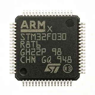
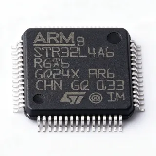
AT32F403ARGT7 - 240MHz Cortex-M4F MCU 1MB Flash | Artery
部品番号: AT32F403ARGT7 ✓ 生産中| 数量 | 単価 | 小計 |
|---|---|---|
| 1 | $1.31 | $1.31 |
| 10 | $1.19 | $11.90 |
| 100 | $1.08 | $108.00 |
| 500 | $0.98 | $490.00 |
| 1,000 | $0.9 | $900.00 |
AT32F403ARGT7 概要
A microcontroller unit (MCU) is a single-chip embedded processor that integrates a CPU core, memory, and peripherals such as timers, ADCs, and communication interfaces onto one die. Within the embedded systems hierarchy, the MCU sits below application processors (MPU/SoC) and above simple logic ICs, and this part belongs to the general-purpose high-performance MCU family built on the ARM Cortex-M architecture.
Key differentiating specifications include the 240 MHz maximum core clock (well above the 72-168 MHz class of typical STM32F1/F4 counterparts), 1 MB of embedded Flash with sLib secure library protection, 17 timers, and 51 GPIO pins. Operating voltage spans 2.6 V to 3.6 V and the junction temperature range is -40C to +105C, covering industrial and automotive-adjacent environments.
Technically, the AT32F403A series combines a single-precision floating-point unit (FPU) and DSP instructions with an advanced process node that Artery leverages to reach 200-240 MHz computing speeds. Peripherals include 3 x 12-bit ADCs, 20 communication interfaces including USBFS, multiple USART/SPI/I2C/CAN blocks, and a flexible clock control mechanism that supports both built-in and external Flash execution.
Typical applications include FPV drone flight controllers, industrial motor control, communication modules and gateways, and consumer electronics where STM32F103-class pinouts are required at higher performance and lower cost. The AT32 family emerged as a proven STM32 alternative during the chip shortage and is widely used as a pin-to-pin upgrade path.
Design consideration: because the 240 MHz core draws more dynamic current than 72 MHz Cortex-M3 parts, budget decoupling capacitance and PCB power-plane copper accordingly, and verify that your flash accelerator/wait-state settings match the higher clock in firmware.
This page synthesizes distributor pricing, drop-in alternatives, pinout data, and practical design notes not found together in the manufacturer datasheet.
ドロップイン代替品: AT32F403ARGT7 — 同一パッケージでピン互換。PCBの作り直しが必要な異なるパッケージの部品は除外されています。
このシリーズのバリエーション
同一シリーズでドロップイン互換のモデル: AT32F403ARGT7 (同一形状・フットプリント) — 相違点: Package, Maximum Clock Frequency, Operating Temperature, RoHS Status, ADC.
クイック比較ツール — 並列比較する代替部品を選択:
AT32F403ARCT7
✅ ドロップイン ⚠️ 仕様未検証📋 参考代替品(カタログ未掲載)
AT32F407ARGT7
✅ ドロップイン ⚠️ 仕様未検証📋 参考代替品(カタログ未掲載)
STM32F103RGT6
✅ ドロップイン✓ 在庫あり
$4.15 / 個
データシートを見る →STM32F103RCT6
✅ ドロップイン✓ 在庫あり
$1.6406 / 個
データシートを見る →APM32F103RGT6
✅ ドロップイン📋 参考代替品(カタログ未掲載)
AT32F403ARGT7 最大定格&電気的特性
| Core | ARM Cortex-M4F with FPU and DSP |
| 最大クロック周波数 | 240 MHz |
| Flash Memory Size | 1 MB |
| SRAM Size | 224 KB |
| Supply Voltage Range | 2.6 V to 3.6 V |
| 動作温度 | -40C to +105C |
| Number of GPIOs | 51 |
| Timers | 17 |
| ADC | 3 x 12-bit ADC |
| Communication Interfaces | 20, including USBFS |
| パッケージ | LQFP-64 (10x10 mm) |
| 実装タイプ | Surface Mount |
| データバス幅 | 32 bit |
| Program Memory Type | Built-in + External Flash supported |
| Security Feature | sLib secure library |
| RoHS ステータス | ROHS compliant |
| Series | AT32F403A |
AT32F403ARGT7 ピン構成
| ピン 1 | VBAT — Battery backup supply for RTC and backup registers |
| ピン 2 | PC13 — GPIO / TAMPER-RTC |
| ピン 3 | PC14 — GPIO / OSC32_IN (32.768 kHz crystal input) |
| ピン 4 | PC15 — GPIO / OSC32_OUT (32.768 kHz crystal output) |
| ピン 5 | PD0 — GPIO / OSC_IN (main crystal input) |
| ピン 6 | PD1 — GPIO / OSC_OUT (main crystal output) |
| ピン 7 | NRST — System reset (active low) |
| ピン 8 | VSSA — Analog ground |
| ピン 9 | VDDA — Analog power supply (ADC/reference) |
| ピン 10 | PA0 — GPIO / WKUP / ADC12_IN0 / TIM2_CH1 |
| ピン 11 | PA1 — GPIO / ADC12_IN1 / TIM2_CH2 |
| ピン 12 | PA2 — GPIO / ADC12_IN2 / USART2_TX / TIM2_CH3 |
| ピン 13 | PA3 — GPIO / ADC12_IN3 / USART2_RX / TIM2_CH4 |
| ピン 14 | PA4 — GPIO / ADC12_IN4 / SPI1_NSS / DAC_OUT1 |
| ピン 15 | PA5 — GPIO / ADC12_IN5 / SPI1_SCK / DAC_OUT2 |
| ピン 16 | PA6 — GPIO / ADC12_IN6 / SPI1_MISO / TIM3_CH1 |
| ピン 17 | PA7 — GPIO / ADC12_IN7 / SPI1_MOSI / TIM3_CH2 |
| ピン 18 | PB0 — GPIO / ADC12_IN8 / TIM3_CH3 |
| ピン 19 | PB1 — GPIO / ADC12_IN9 / TIM3_CH4 |
| ピン 20 | PB2 — GPIO / BOOT1 |
| ピン 21 | PB10 — GPIO / I2C2_SCL / USART3_TX / TIM2_CH3 remap |
| ピン 22 | PB11 — GPIO / I2C2_SDA / USART3_RX |
| ピン 23 | VSS — Digital ground |
| ピン 24 | VDD — Digital power supply 2.6 V to 3.6 V |
| ピン 25 | PB12 — GPIO / SPI2_NSS / I2C2_SMBA / TIM1_BKIN |
| ピン 26 | PB13 — GPIO / SPI2_SCK / TIM1_CH1N |
| ピン 27 | PB14 — GPIO / SPI2_MISO / TIM1_CH2N |
| ピン 28 | PB15 — GPIO / SPI2_MOSI / TIM1_CH3N |
| ピン 29 | PC6 — GPIO / TIM3_CH1 remap / I2S2_MCK |
| ピン 30 | PC7 — GPIO / TIM3_CH2 remap |
| ピン 31 | PC8 — GPIO / TIM3_CH3 remap |
| ピン 32 | PC9 — GPIO / TIM3_CH4 remap |
| ピン 33 | PA8 — GPIO / USART1_CK / TIM1_CH1 / MCO |
| ピン 34 | PA9 — GPIO / USART1_TX / TIM1_CH2 |
| ピン 35 | PA10 — GPIO / USART1_RX / TIM1_CH3 |
| ピン 36 | PA11 — GPIO / USBFS_DM / CAN_RX / TIM1_CH4 |
| ピン 37 | PA12 — GPIO / USBFS_DP / CAN_TX |
| ピン 38 | PA13 — GPIO / SWDIO (serial wire debug data) |
| ピン 39 | VSS — Digital ground |
| ピン 40 | VDD — Digital power supply 2.6 V to 3.6 V |
| ピン 41 | PA14 — GPIO / SWCLK (serial wire debug clock) |
| ピン 42 | PA15 — GPIO / SPI1_NSS remap / TIM2_CH1 remap |
| ピン 43 | PC10 — GPIO / UART4_TX / SPI3_SCK remap |
| ピン 44 | PC11 — GPIO / UART4_RX / SPI3_MISO remap |
| ピン 45 | PC12 — GPIO / UART5_TX / SPI3_MOSI remap |
| ピン 46 | PD2 — GPIO / UART5_RX / TIM3_ETR |
| ピン 47 | PB3 — GPIO / SPI1_SCK remap / TIM2_CH2 remap / JTDO |
| ピン 48 | PB4 — GPIO / SPI1_MISO remap / TIM3_CH1 remap / NJTRST |
| ピン 49 | PB5 — GPIO / SPI1_MOSI remap / I2C1_SMBA / TIM3_CH2 remap |
| ピン 50 | PB6 — GPIO / I2C1_SCL / TIM4_CH1 / USART1_TX remap |
| ピン 51 | PB7 — GPIO / I2C1_SDA / TIM4_CH2 / USART1_RX remap |
| ピン 52 | BOOT0 — Boot mode selection pin |
| ピン 53 | PB8 — GPIO / I2C1_SCL remap / TIM4_CH3 / CAN_RX remap |
| ピン 54 | PB9 — GPIO / I2C1_SDA remap / TIM4_CH4 / CAN_TX remap |
| ピン 55 | VSS — Digital ground |
| ピン 56 | VDD — Digital power supply 2.6 V to 3.6 V |
| ピン 57 | PC0 — GPIO / ADC123_IN10 |
| ピン 58 | PC1 — GPIO / ADC123_IN11 |
| ピン 59 | PC2 — GPIO / ADC123_IN12 |
| ピン 60 | PC3 — GPIO / ADC123_IN13 |
| ピン 61 | PC4 — GPIO / ADC12_IN14 |
| ピン 62 | PC5 — GPIO / ADC12_IN15 |
| ピン 63 | PB0B — Alternate function per AT32F403A pin remap (refer to datasheet pin definition chapter) |
| ピン 64 | PB1B — Alternate function per AT32F403A pin remap (refer to datasheet pin definition chapter) |
主な用途
AT32F403ARGT7 の用途: 6 件s: FPV Drone Flight Controllers, Industrial Motor Control, Communication Modules and Gateways, STM32F103 Drop-in Upgrade Boards, Consumer Electronics and White Goods, Test and Measurement Instruments.
FPV Drone Flight Controllers
The AT32F403ARGT7 is a leading MCU choice for FPV flight controllers because its 240 MHz Cortex-M4F with hardware FPU executes 8 kHz gyro sampling and PID control loops with large timing margins, while the 224 KB SRAM accommodates multi-buffer sensor pipelines (SPI gyro plus barometer plus magnetometer). The 51 GPIOs and 17 timers expose the PWM/DShot outputs and multiple UARTs typical of race-class FC boards. Because the pin map is STM32F103-compatible, FC designers can reuse proven LQFP-64 layouts and migrate firmware with modest peripheral adaptation, gaining F7-class throughput at roughly F4-level cost (about $1.31 per unit as of 2026-10-19).
おすすめ
Industrial Motor Control
Three 12-bit ADCs with simultaneous sampling and 17 timers (including advanced timers with complementary PWM outputs and dead-band insertion) make the AT32F403ARGT7 well suited to FOC brushless and PMSM motor drives. The 240 MHz core performs Clarke/Park transforms with the single-precision FPU at rates above 20 kHz without fixed-point compromise, and 224 KB SRAM holds field-oriented control state machines plus communication stacks concurrently. Operating from a 2.6 V to 3.6 V supply over -40C to +105C, the part meets industrial enclosure temperature requirements, while sLib code protection safeguards proprietary control algorithms stored in the 1 MB embedded Flash.
おすすめ
Communication Modules and Gateways
With 20 communication interfaces - multiple USARTs, SPI, I2C, CAN, and USBFS - the AT32F403ARGT7 aggregates data from radios, RS-485 fieldbuses, and sensors in industrial gateways and IoT concentrators. The 1 MB Flash supports protocol stacks (Modbus, MQTT-over-modem AT handlers) plus an OTA bootloader simultaneously, and 224 KB SRAM buffers burst traffic between asymmetric-speed interfaces. The flexible clock control mechanism allows running peripherals from lower-speed clocks to cut EMI while keeping the 240 MHz core available for packet processing, a useful trade-off in CE/FCC-sensitive wireless products sharing the STM32F103-style footprint.
おすすめ
STM32F103 Drop-in Upgrade Boards
The AT32F403ARGT7 functions as a pin-to-pin performance upgrade for STM32F103RGT6/RCT6-based designs in the LQFP-64 package: identical pin ordering (VBAT, PC13, BOOT0, and GPIO placement), the same 2.6 V to 3.6 V supply window, and RoHS-compliant construction. Boards gain 3.3x clock speed (240 MHz vs 72 MHz), an FPU, and 2.3x SRAM without PCB respin. This positioning drove its adoption during the STM32 shortage era, and it remains a cost-reduction lever (about $1.31 at qty 1 as of 2026-10-19) for legacy boards. Firmware requires recompilation for Artery peripherals and re-validation of USB, timers, and ADC edge cases.
おすすめ
Consumer Electronics and White Goods
In appliances, chargers, and smart-home devices, the AT32F403ARGT7 provides headroom for capacitive-touch decoding, voice-prompt playback, and display driving that stresses 72 MHz MCUs. The 3 x 12-bit ADCs handle multiple analog sensor channels (NTC temperature, potentiometers, current sense), USBFS supports charging-port communication, and the 1 MB Flash stores GUI assets plus a field-updatable application image in one device. The -40C to +105C range and 2.6 V to 3.6 V operation tolerate kitchen and outdoor environmental conditions, while the roughly $1 volume price keeps the BOM competitive against domestic Cortex-M0/M3 alternatives at higher clock speeds.
おすすめ
Test and Measurement Instruments
Bench accessories such as programmable loads, signal generators, and data loggers benefit from the AT32F403ARGT7's combination of 240 MHz processing, three 12-bit ADCs for multi-channel acquisition, and 17 timers for precise PWM/DAC-like waveform synthesis. The 224 KB SRAM sustains deep sample buffers for 1 MSPS-class logging, while USBFS streams data to host PCs without a separate USB bridge chip. sLib secure library protection lets instrument vendors ship firmware with calibration constants protected against extraction, and the LQFP-64 10x10 mm footprint integrates into compact handheld enclosures at industrial temperature ratings up to +105C.
おすすめ
おすすめ製品の概要
エンジニアリング参考データ: AT32F403ARGT7 — 比較、設計ガイダンス、コンプライアンス情報。
選定ガイド
代替品との比較
| パラメータ | この製品 | AT32F403ARCT7 | AT32F407ARGT7 | STM32F103RGT6 | STM32F103RCT6 | APM32F103RGT6 |
|---|---|---|---|---|---|---|
| Package | LQFP-64 (10x10 mm) | LQFP-64 (10x10 mm) - same | LQFP-64 (10x10 mm) - same | LQFP-64 (10x10 mm) - same | LQFP-64 (10x10 mm) - same | LQFP-64 (10x10 mm) - same |
| Brand | Artery Technology | Artery Technology | Artery Technology | STMicroelectronics | STMicroelectronics | Geehy Semiconductor |
| Core / Max Clock | Cortex-M4F, 240 MHz | Cortex-M4F, 240 MHz | Cortex-M4F, 240 MHz | Cortex-M3, 72 MHz | Cortex-M3, 72 MHz | Cortex-M3, 120 MHz |
| Flash | 1 MB | 256 KB | 1 MB | 1 MB | 256 KB | 1 MB |
| FPU | Yes (single precision) | Yes (single precision) | Yes (single precision) | No | No | No |
| Supply Voltage | 2.6 V to 3.6 V | 2.6 V to 3.6 V | 2.6 V to 3.6 V | 2.0 V to 3.6 V | 2.0 V to 3.6 V | 2.0 V to 3.6 V |
主な差別化要因
- 3.3x CPU throughput in the same footprint (vs STM32F103RGT6)
- Hardware floating-point unit (vs STM32F103RGT6)
- Larger SRAM buffer capacity (vs STM32F103RCT6)
- Cost per MHz trade-off (vs STM32F103RGT6)
設計ノート
Estimated: at 240 MHz, core dynamic current is significantly higher than a 72 MHz Cortex-M3 part; budget a low-ESR 10 uF bulk capacitor plus 0.1 uF ceramic caps at every VDD pin pair (pins 24/23, 40/39, 56/55) and a separate LC-filtered VDDA (pin 9) with a 1 uF + 10 nF network for the ADCs. Keep VDDA ripple below a few mV to preserve 12-bit ADC effective resolution. Verify actual Idd figures against the DC characteristics tables of the Artery AT32F403A datasheet for your clock configuration.
Place the 0.1 uF decoupling capacitors within 2 mm of each VDD pin with solid ground return vias. Route USBFS_DM/DP (pins 36/37) as a 90-ohm differential pair with length matching within 1 mm and reference a continuous ground plane. Keep the NRST (pin 7) trace short with a 100 nF capacitor to ground near the pin, and expose BOOT0 (pin 52) to a jumper or test point so the bootloader remains accessible for in-system programming after assembly.
The most common migration mistake from STM32F103 boards is assuming register-level identity: the AT32F403A flash accelerator and clock tree configuration differ, and running firmware compiled for 72 MHz without reconfiguring PLL and wait states will either fail to boot or run at the wrong speed. Also confirm the supply window: this Artery part specifies 2.6 V minimum versus 2.0 V on STM32F103, so a slightly sagging 3.3 V rail under load should be measured across the full operating temperature range before mass production.
コンプライアンス情報
ROHS compliance stated by LCSC and JLCPCB listings. REACH, lead-free, halogen-free, and conflict-minerals declarations not stated in the provided data - request certificate of conformity from Artery.