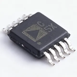
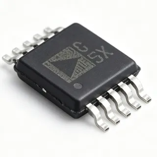
MCP3423-E/UN - 18-Bit Dual Delta-Sigma ADC | Microchip
部品番号: MCP3423-E/UN ✓ 生産中MCP3423-E/UN 概要
An ADC is an analog-to-digital converter, a semiconductor that converts continuous voltage signals into digital codes for processing, measurement, logging, or control. The MCP3423 belongs to the delta-sigma ADC hierarchy, where an internal modulator and digital filtering provide high resolution and low noise at relatively low conversion rates. It is therefore suited to precision measurements rather than high-speed waveform capture.
Key features include two analog input channels, up to 18-bit resolution, differential input capability, an on-board 2.048 V reference, and an I2C digital interface. The 2.048 V reference establishes the differential input scale for each conversion, while the dual-channel architecture allows related measurements to be captured without changing the converter package. The 10-MSOP format supports compact, surface-mount instrumentation designs.
Technically, the MCP3423 combines a delta-sigma conversion stage with on-chip noise rejection and digital decimation. Low-rate conversion allows the converter to reject out-of-band noise effectively, while the integrated reference reduces the number of external precision components required. The I2C interface provides a compact connection to microcontrollers, sensors, data loggers, and industrial measurement equipment, although the maximum bus and interface timing details require confirmation from the manufacturer datasheet.
Typical uses include bridge or load-cell signal acquisition, industrial process monitoring, low-frequency sensor measurement, laboratory instrumentation, and portable data acquisition. Differential inputs are particularly useful when the measured signal is small and a differential amplifier or low-level front end converts it into the converter's allowed input range. The device is not positioned as a high-speed SAR ADC because its listed conversion rate is approximately 4 SPS.
Designers should verify analog input common-mode limits, reference accuracy, supply requirements, digital interface timing, and the required gain configuration against the manufacturer datasheet before layout. Input filtering and source impedance remain important because the selected conversion rate and digital filter determine the usable bandwidth; filtering too aggressively can delay settling, while insufficient filtering can admit unwanted out-of-band noise.
This product page consolidates verified manufacturer and distributor information, pricing, package details, design guidance, and the available drop-in cross-reference. It is intended to help engineers identify the correct MCP3423-E/UN variant and distinguish a genuine same-package replacement from a merely similar converter.
ドロップイン代替品: MCP3423-E/UN — 同一パッケージでピン互換。PCBの作り直しが必要な異なるパッケージの部品は除外されています。
MCP3423T-E/MF
✅ ドロップイン📋 参考代替品(カタログ未掲載)
MCP3423-E/UN 最大定格&電気的特性
| Converter Type | 18-bit delta-sigma ADC |
| Number of Input Channels | 2 channels |
| Maximum Resolution | 18 bits |
| Input Architecture | Differential inputs |
| Internal Reference Voltage | 2.048 V |
| Differential Input Range | ±2.048 V |
| Conversion Rate | Up to 4 SPS |
| Digital Interface | I2C |
| パッケージ | 10-MSOP |
| 実装タイプ | Surface mount |
MCP3423-E/UN 10-msop ピン配置ガイド
MCP3423-E/UN (10-msop パッケージ) のピン配置。 このアナログコンポーネントは、入力、出力、および電源ピンを備えています。オフセットナル、補償、イネーブルピンの設定については、メーカーのデータシートを参照してください。信号調整やアンプ回路に最適です。

詳細なピン配置データはありません: MCP3423-E/UN.
詳細は データシート をご参照ください。
主な用途
MCP3423-E/UN の用途: 6 件s: Load-Cell Signal Acquisition, Industrial Process Monitoring, Precision Sensor Interface, Laboratory Data Acquisition, Environmental Monitoring, Portable Instrumentation.
Load-Cell Signal Acquisition
The MCP3423-E/UN fits load-cell and other low-level bridge measurements that require differential signal capture, high resolution, and a compact converter footprint. Its two differential channels and up to 18-bit resolution are appropriate for monitoring force, weight, or pressure, while the 2.048 V internal reference provides a defined differential measurement scale. A bridge amplifier or suitable instrumentation front end should translate the bridge output into the converter's permitted common-mode and differential range. The maximum 4 SPS conversion rate suits static or slowly changing loads rather than dynamic vibration analysis. Confirm analog input limits, gain options, excitation requirements, and digital filtering in the manufacturer datasheet before finalizing the signal chain.
Industrial Process Monitoring
The MCP3423-E/UN is suitable for industrial process measurements where accuracy and noise rejection are more important than acquisition speed. Its differential inputs can accept suitably conditioned pressure, temperature, level, or flow signals while rejecting common-mode disturbance present on long sensor wiring. Up to 18-bit resolution provides fine digital code spacing, and the integrated 2.048 V reference reduces reliance on an external reference for suitable measurement ranges. The I2C interface allows connection to an embedded controller for configuration and data retrieval. At up to 4 SPS, the part is best applied to slow process variables rather than high-bandwidth control loops. Field designs should include appropriate input protection, filtering, grounding, and isolation where required by the installation.
Precision Sensor Interface
The MCP3423-E/UN can serve as the analog front end for low-frequency precision sensors whose output changes slowly and benefits from differential measurement. Its two-channel architecture supports paired or related measurements, while the 10-MSOP package keeps the converter compact beside sensor-conditioning circuitry. The onboard 2.048 V reference and up to 18-bit resolution can improve observability in applications otherwise constrained by sensor output amplitude and system noise. Use a low-noise, low-offset amplifier when the sensor output is too small or outside the common-mode range. The 4 SPS limit means the digital filter and conversion latency must be considered in closed-loop or event-based systems. Input settling and filter bandwidth should be verified using the manufacturer timing and electrical data.
Laboratory Data Acquisition
The MCP3423-E/UN is appropriate for laboratory measurement systems that record slowly varying voltages with relatively high resolution. Two differential inputs can capture a sensor signal and a related reference, auxiliary channel, or differential output from an instrumentation amplifier. The converter's integrated 2.048 V reference supports repeatable measurements when its accuracy and drift meet the instrument specification, while the I2C interface simplifies connection to an embedded control board. Because the maximum listed conversion rate is 4 SPS, the device is not intended for general-purpose oscilloscope acquisition. Use it for thermocouple, strain-gauge, laboratory transducer, and environmental monitoring channels after confirming input common-mode limits, gain, and filter settling requirements.
Environmental Monitoring
The MCP3423-E/UN can digitize slow environmental measurements such as temperature, humidity, pressure, and gas-sensor outputs in compact monitoring instruments. Its differential inputs are useful when the sensor or amplifier produces a bipolar signal around a common reference, while the up to 18-bit resolution can preserve detail in slowly changing measurements. The 4 SPS conversion rate is adequate for ambient monitoring and battery-powered environmental nodes that update readings periodically. The internal 2.048 V reference and I2C interface help reduce component count and board space, although reference drift, sensor self-heating, and noise must be included in the error budget. Protective filtering and layout isolation are particularly important when the converter shares a board with switching converters or long external sensor cables.
Portable Instrumentation
The MCP3423-E/UN fits portable, low-power instrumentation that measures low-frequency analog signals in a compact package. Its 10-MSOP footprint leaves board area for the sensor interface, I2C host, and power circuitry, while two channels allow useful measurement multiplexing without adding another converter package. The delta-sigma architecture, up to 18-bit resolution, and integrated 2.048 V reference support accurate readings from bridge and instrumentation-amplifier outputs. A conversion rate up to 4 SPS is appropriate for sampled readings rather than continuous waveform capture. Portable-product designers should verify supply range and current consumption, which were not supplied in the verified results, and should account for reference performance over the product's environmental temperature range.
エンジニアリング参考データ: MCP3423-E/UN — 比較、設計ガイダンス、コンプライアンス情報。
選定ガイド
代替品との比較
| パラメータ | この製品 | MCP3423T-E/MF |
|---|---|---|
| Package | 10-MSOP | 10-MSOP |
| Brand | Microchip Technology | Microchip Technology |
| Converter Type | Delta-sigma ADC | Delta-sigma ADC |
| Maximum Resolution | 18 bits | 18 bits |
| Number of Input Channels | 2 channels | 2 channels |
| Internal Reference | 2.048 V | 2.048 V |
| Differential Input Range | ±2.048 V | ±2.048 V |
| Conversion Rate | Up to 4 SPS | Up to 4 SPS |
| Digital Interface | I2C | I2C |
主な差別化要因
- Two-channel differential measurement architecture (vs MCP3423T-E/MF)
- Integrated precision measurement reference (vs MCP3423T-E/MF)
- Low-noise precision conversion positioning (vs MCP3423T-E/MF)
設計ノート
Do not treat the ±2.048 V differential range as permission to apply any arbitrary voltage to either input pin. Confirm the absolute input voltage, common-mode range, permitted gain configurations, and overvoltage behavior in the manufacturer datasheet. The differential specification describes the allowable signal span, while the individual input pins can have a narrower legal common-mode operating region.
Keep the analog input path short and guard against switching-node interference. Place input filtering close to the MCP3423-E/UN, use a low-noise analog front end when the source impedance is high, and avoid routing sensitive input traces beside inductors, switching converters, or high-current return paths. Select the digital filter and conversion rate so the useful sensor bandwidth is retained without aliasing.
Separate analog and digital return currents where practical, provide a quiet ground reference for the converter and its input amplifier, and place the bypass capacitor at the device supply pins. Because the verified data did not include the complete pinout or decoupling values, use the package drawing and typical application circuit in the manufacturer documentation for exact placement rather than relying on generic layouts.
コンプライアンス情報
The supplied verified web data did not state RoHS, REACH, AEC-Q100, lead-free, halogen-free, or conflict-minerals status for MCP3423-E/UN. These fields remain unknown rather than being inferred.