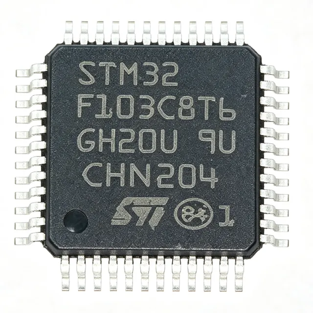
STM32F103C8T6 - 32ビットARM Cortex-M3 MCU、64KBフラッシュ | STMicroelectronics
部品番号: STM32F103C8T6 ✓ 生産中| 数量 | 単価 | 小計 |
|---|---|---|
| 1 | $1.93 | $1.93 |
| 10 | $1.33 | $13.30 |
| 100 | $1.18 | $118.00 |
| 500 | $1.11 | $555.00 |
| 1,000 | $1.08 | $1,080.00 |
| 1,500 | $1.02 | $1,530.00 |
STM32F103C8T6 概要
ドロップイン代替品: STM32F103C8T6 — 同一パッケージでピン互換。PCBの作り直しが必要な異なるパッケージの部品は除外されています。
このシリーズのバリエーション
同一シリーズでドロップイン互換のモデル: STM32F103C8T6 (同一形状・フットプリント) — 相違点: Package, Core, Flash Memory, Operating Temperature, SRAM.
クイック比較ツール — 並列比較する代替部品を選択:
STM32F103CBT6
✓ 在庫あり
$3.2 / 個
データシートを見る →GD32F103C8T6
📋 参考代替品(カタログ未掲載)
STM32F103R8T6
✓ 在庫あり
$2.9 / 個
データシートを見る →APM32F103C8T6
📋 参考代替品(カタログ未掲載)
STM32F030C8T6
✓ 在庫あり
$0.98 / 個
データシートを見る →STM32F103C8T6 最大定格&電気的特性
| Core | ARM Cortex-M3 |
| Max Clock Frequency | 72 MHz |
| Flash Memory | 64 KB |
| SRAM | 20 KB |
| 電源電圧 | 2.0 V to 3.6 V |
| 動作温度 | -40C to +85C |
| パッケージ | LQFP-48 |
| 実装タイプ | Surface Mount |
| Number of I/Os | 37 |
| ADC Resolution | 12-bit |
| Number of ADC Channels | 10 |
| Timer Modules | 3 general-purpose, 1 advanced |
| Communication Interfaces | USART (2), SPI (2), I2C (2), USB 2.0 FS, CAN 2.0B |
| DMA Channels | 7 |
| Debug Interface | SWD, JTAG |
| RoHS ステータス | Compliant |
STM32F103C8T6 ピン構成
| ピン 1 | VBAT — Battery backup for RTC |
| ピン 2 | PC13 — GPIO, also used for RTC tamper |
| ピン 3 | PC14 — GPIO, also used for OSC32_IN |
| ピン 4 | PC15 — GPIO, also used for OSC32_OUT |
| ピン 5 | OSC_IN — Main oscillator input |
| ピン 6 | OSC_OUT — Main oscillator output |
| ピン 7 | NRST — Reset (active low) |
| ピン 8 | VSSA — Analog ground |
| ピン 9 | VDDA — Analog power supply |
| ピン 10 | PA0 — GPIO, ADC12_IN0, TIM2_CH1 |
| ピン 11 | PA1 — GPIO, ADC12_IN1, TIM2_CH2 |
| ピン 12 | PA2 — GPIO, ADC12_IN2, TIM2_CH3 |
| ピン 13 | PA3 — GPIO, ADC12_IN3, TIM2_CH4 |
| ピン 14 | PA4 — GPIO, SPI1_NSS, DAC_OUT1 |
| ピン 15 | PA5 — GPIO, SPI1_SCK, DAC_OUT2 |
| ピン 16 | PA6 — GPIO, SPI1_MISO, TIM3_CH1 |
| ピン 17 | PA7 — GPIO, SPI1_MOSI, TIM3_CH2 |
| ピン 18 | PB0 — GPIO, TIM3_CH3, ADC12_IN8 |
| ピン 19 | PB1 — GPIO, TIM3_CH4, ADC12_IN9 |
| ピン 20 | PB2 — GPIO, BOOT1 |
| ピン 21 | PB10 — GPIO, I2C2_SCL, USART3_TX |
| ピン 22 | PB11 — GPIO, I2C2_SDA, USART3_RX |
| ピン 23 | PB12 — GPIO, SPI2_NSS, I2C2_SMBA |
| ピン 24 | PB13 — GPIO, SPI2_SCK, USART3_CTS |
| ピン 25 | PB14 — GPIO, SPI2_MISO, USART3_RTS |
| ピン 26 | PB15 — GPIO, SPI2_MOSI, TIM1_CH3N |
| ピン 27 | PC13 — GPIO, RTC_AF1 |
| ピン 28 | PC14 — GPIO, OSC32_IN |
| ピン 29 | PC15 — GPIO, OSC32_OUT |
| ピン 30 | VSS_1 — Ground |
| ピン 31 | VDD_1 — Power supply |
| ピン 32 | VDDA — Analog power supply |
| ピン 33 | VSSA — Analog ground |
| ピン 34 | PA8 — GPIO, TIM1_CH1, MCO |
| ピン 35 | PA9 — GPIO, TIM1_CH2, USART1_TX |
| ピン 36 | PA10 — GPIO, TIM1_CH3, USART1_RX |
| ピン 37 | PA11 — GPIO, USART1_CTS, USB_DM |
| ピン 38 | PA12 — GPIO, USART1_RTS, USB_DP |
| ピン 39 | PA13 — GPIO, SWDIO |
| ピン 40 | PA14 — GPIO, SWCLK |
| ピン 41 | PA15 — GPIO, JTDI |
| ピン 42 | PB3 — GPIO, JTDO |
| ピン 43 | PB4 — GPIO, NJTRST |
| ピン 44 | PB5 — GPIO, I2C1_SMBA |
| ピン 45 | PB6 — GPIO, I2C1_SCL, TIM4_CH1 |
| ピン 46 | PB7 — GPIO, I2C1_SDA, TIM4_CH2 |
| ピン 47 | BOOT0 — Boot mode selection |
| ピン 48 | VDD_2 — Power supply |
主な用途
STM32F103C8T6 の用途: 6 件s: Industrial Control, IoT Gateway, Medical Monitoring Device, Automotive Body Control, Consumer Electronics, Data Logging System.
Industrial Control
Used in PLCs, motor drives, and automation controllers.
IoT Gateway
Acts as a central hub for sensor data collection and communication.
Medical Monitoring Device
Powers portable health monitors with low-power operation.
Automotive Body Control
Manages lighting, wipers, and window controls.
Consumer Electronics
Embedded in smart home devices, drones, and toys.
Data Logging System
Records sensor data to SD card or transmits via USB.