Produk (44,000+)

MCP2515T-E/SO - 1 Mbps CAN 2.0B Controller | Microchip Technology
MCP2515T-E/SO

MCP2515T-E/SO - 1 Mbps CAN 2.0B Controller | Microchip Technology

The Microchip Technology MCP2515T-E/SO is a stand-alone CAN 2.0B controller supporting data rates up to 1 Mbps, standard and extended data frames, remote frames, and an SPI host interface in an 18-pin SOIC package. It operates from a 5 V supply, supports 3.3 V and 5 V operation in sleep or standby modes, and is rated for temperatures from -40 °C to 125 °C. A CAN controller is a semiconductor that manages CAN frames while a separate CAN transceiver connects the controller to the physical bus. The MCP2515T-E/SO sits between a microcontroller or host processor and that transceiver, providing bit timing, arbitration, error handling, receive buffers, masks, and filters. This separates protocol processing from the analog and electrical functions required by a CAN bus. The controller supports CAN 2.0B standard and extended identifiers, two receive buffers, programmable acceptance masks and filters, and remote transmission requests. It also adds upgraded throughput, data-byte filtering, and support for time-triggered protocols compared with the earlier MCP2510. These features make it useful for industrial equipment, automotive accessories, instrumentation, and embedded control systems. Internally, the device combines a CAN protocol engine with an SPI interface for host register access. The SPI connection allows a host processor to configure bit timing, select filters, initiate transmissions, retrieve received frames, and monitor interrupt status. The controller requires an external clock source, CAN transceiver, bus termination, decoupling, and careful transceiver interface layout to create a working CAN node. Typical applications include industrial automation controllers, vehicle diagnostic interfaces, building-control gateways, robotics equipment, test systems, and embedded CAN protocol bridges. In each case, the MCP2515T-E/SO provides the CAN frame engine while a host MCU handles application logic and a transceiver such as the site-listed TCAN334D, TCAN332DR, or TCAN330DR provides the physical-layer connection. Designers should use short, well-routed SPI traces, provide the required supply and ground decoupling, and verify oscillator and transceiver timing margins across the complete CAN network. The 125 °C maximum operating temperature makes the device suitable for industrial environments, but the exact package pinout and PCB land pattern should be checked against the current manufacturer datasheet before layout release. This product record combines verified manufacturer and distributor information with practical CAN-node design guidance, pricing context, package details, and application-specific engineering considerations that are not consolidated in the original catalog snippets.

RFC Hubungi kami
MCP2515T-E/SOVAO CAN 2.0B Controller | Microchip Technology
MCP2515T-E/SOVAO

MCP2515T-E/SOVAO CAN 2.0B Controller | Microchip Technology

The Microchip Technology MCP2515T-E/SOVAO is a stand-alone Controller Area Network controller implementing CAN specification Version 2.0B, with an SPI host interface and an 18-SOIC package. It supports standard data frames, extended data frames, and remote frames for both transmission and reception. Verified distributor data identifies the device as an automotive-temperature CAN interface IC, while the manufacturer describes the MCP2515 family as a second-generation controller that is pin- and function-compatible with the MCP2510. A CAN controller is a communications integrated circuit that manages frame assembly, filtering, arbitration-related status, interrupts, and host-controller communication on a CAN bus. In system hierarchy, the MCP2515 belongs to CAN interface controllers and then to broader interface ICs. Its stand-alone architecture allows a host microcontroller to manage CAN traffic through SPI rather than embedding a complete CAN peripheral in the host itself. The MCP2515 family adds faster throughput, data-byte filtering, and support for time-triggered protocols relative to the MCP2510. The controller is designed for systems that need independent access to CAN message buffers and status information. This separation can make protocol timing and interrupt handling easier to organize, especially when the host uses a different real-time workload than the CAN network. The MCP2515T-E/SOVAO is supplied in an 18-SOIC gull-wing package. The verified part designation includes the T temperature option and E qualification suffix, but the retrieved source snippets do not provide a complete electrical parameter table for this exact ordering code. Consequently, detailed supply voltage, transceiver-interface voltage, reset behavior, oscillator requirements, absolute maximum ratings, and timing values remain marked for verification rather than inferred from unrelated variants. Typical applications include automotive and industrial CAN networks, embedded control modules, instrumentation gateways, vehicle diagnostics, factory automation equipment, and transport systems. In these systems, a host processor connects through SPI while the MCP2515 exchanges CAN frames with a separate CAN transceiver. This division allows the controller to provide frame handling while the transceiver converts logic-level signals into the physical CAN bus differential signals. Designers should verify the exact MCP2515T-E/SOVAO electrical limits, timing, and qualification claims in the manufacturer datasheet before release. PCB layout should provide a controlled SPI bus, a stable oscillator implementation, proper decoupling, and a clean interface to the CAN transceiver. This page synthesizes the verified manufacturer and distributor data with application guidance while avoiding unsupported electrical claims.

RFC Hubungi kami
MCP2515T-E/ST - 1 Mbps CAN 2.0B Controller | Microchip Technology
MCP2515T-E/ST

MCP2515T-E/ST - 1 Mbps CAN 2.0B Controller | Microchip Technology

Microchip Technology MCP2515T-E/ST is a stand-alone Controller Area Network controller implementing CAN specification version 2.0B, with a maximum data transmission speed of 1 Mbps and an SPI host interface. The device is supplied in a 20-pin TSSOP package and supports standard data frames, extended data frames, and remote frames. A CAN controller is a communications IC that converts host commands into CAN frames and converts received CAN traffic into data available through a serial interface. Within the broader hierarchy, the MCP2515T-E/ST is a CAN interface controller and therefore belongs to the interface IC, CAN controller, industrial communication, and embedded networking domains. It connects a microcontroller or other host processor to a CAN bus through an external CAN transceiver. The second-generation MCP2515 architecture provides faster throughput, byte-level filtering, and support for time-triggered protocols. According to the Microchip Technology MCP2515 family datasheet, it can both transmit and receive standard, extended, and remote frames. Its SPI interface allows register configuration, interrupt handling, and frame exchange with a host microcontroller while keeping the CAN physical-layer implementation in a separate transceiver. The MCP2515T-E/ST operates from a 3.3 V or 5 V supply in Sleep and Standby modes, and the associated component listing identifies a maximum operating temperature of 125°C. It is intended for both 3.3 V and 5 V embedded systems and supports designs that require reception filters, interrupt-driven bus management, or scheduled time-triggered communication. Typical applications include industrial automation equipment, automotive and transportation modules, building-control systems, robotics, medical instruments, and embedded data-acquisition equipment. It is especially suitable when an existing host controller already uses SPI and the design needs a dedicated CAN protocol engine instead of implementing CAN framing in host software. The principal design consideration is that the MCP2515T-E/ST is a controller, not a CAN transceiver. The PCB therefore needs a suitable 3.3 V or 5 V CAN transceiver, proper bus termination, protection appropriate to the environment, and a carefully routed connection between the controller and transceiver. Firmware must also initialize the bit timing, configure acceptance filters, select clock and interrupt settings, and handle bus-off recovery according to the device register definitions.

RFC Hubungi kami
MCP2515T-I/ML - 1Mbps SPI CAN Controller | Microchip Technology
MCP2515T-I/ML

MCP2515T-I/ML - 1Mbps SPI CAN Controller | Microchip Technology

The Microchip Technology MCP2515T-I/ML is a stand-alone Controller Area Network controller supporting CAN 2.0B communication at up to 1 Mbps through an SPI interface, and it is housed in a 20-pin QFN package with an exposed pad measuring approximately 4 x 4 mm. The device operates from a 2.7 V to 5.5 V supply and is specified for a -40°C to +85°C industrial temperature range. Its protocol implementation supports standard data frames, extended data frames, and remote frames. A CAN controller is a semiconductor that manages frame creation, arbitration, acknowledgment, error detection, and bus data movement according to the Controller Area Network standard. The MCP2515 belongs to the hierarchy of CAN controller, communication controller, interface IC, and semiconductor. Unlike a CAN physical-layer transceiver, it does not directly connect to the bus's differential CANH and CANL conductors. It instead exchanges commands and status data with a host processor over SPI while a separate transceiver converts the controller's logic signals to the physical bus. The MCP2515 provides two receive buffers, acceptance masks, and acceptance filters for selecting CAN identifiers. These features help the host avoid processing irrelevant traffic. It also includes interrupt signaling, request-to-send control, programmable bit timing, loopback and silent modes, and a standby low-power state. A 1 Mbps bus rate supports demanding industrial and automotive networking, although the final operating rate depends on oscillator accuracy, transceiver characteristics, wiring, termination, and network topology. The controller's SPI host interface provides an effective separation between real-time bus handling and host-side protocol software. The processor can configure bit timing and filters, place messages into transmit buffers, retrieve received frames, and read interrupt status without bit-banging the CAN bus. The exposed thermal pad provides a direct heat-transfer path to the PCB, while the small QFN footprint supports compact controller modules and embedded equipment. Internal timing references and external-clock arrangements must follow the manufacturer's pin and application guidance. Typical uses include industrial automation equipment, vehicle diagnostic interfaces, building-control gateways, embedded motor-control systems, CAN-to-SPI bridges, and communications modules. It is especially appropriate when a microcontroller lacks a native CAN peripheral or when a dedicated controller allows the host processor to share communication tasks. A physical-layer transceiver such as an MCP2551-class device remains necessary in every practical CAN bus implementation. Designers should follow the recommended decoupling, grounding, exposed-pad soldering, and high-speed layout practices in the manufacturer datasheet. Keep the SPI clock and signal routes compact, provide a low-impedance ground return, place input and output capacitors close to their pins, and connect the exposed pad to the ground plane with an adequate thermal-via pattern. Confirm oscillator and bit-timing settings at the intended bus speed because incorrect oscillator configuration or inadequate transceiver propagation delay can prevent reliable arbitration. This product page combines the device's core protocol and package characteristics with practical integration guidance, verified sourcing links, and an honest assessment of available drop-in alternatives. It is intended to help engineers select the controller, plan its PCB implementation, and evaluate replacement options without confusing protocol equivalence with true package-level drop-in compatibility.

RFC Hubungi kami
MCP2515T-I/SO - 1 Mbps CAN Controller with SPI | Microchip Technology
MCP2515T-I/SO

MCP2515T-I/SO - 1 Mbps CAN Controller with SPI | Microchip Technology

The Microchip Technology MCP2515T-I/SO is a stand-alone CAN controller with an SPI interface, implementing CAN specification Version 2.0B at up to 1 Mb/s. The device supports standard and extended data frames, remote frames, receive buffers, masks and filters, and is housed in an 18-pin SOIC package. It is designed for systems where a host microcontroller communicates with a CAN bus through a serial peripheral interface rather than integrating a CAN controller directly. A CAN controller, also called a CAN protocol controller, is an interface IC within the broader network interface and communications semiconductor category. It manages CAN frame transmission and reception while a host processor configures registers, reads status information, and exchanges data through SPI. The MCP2515 family is positioned between simple serial transceivers and more integrated CAN solutions because it provides protocol handling without requiring the host MCU to implement the complete CAN frame format. Key features of the MCP2515 include CAN 1 Mb/s operation, support for both standard and extended identifiers, two receive buffers, programmable acceptance masks and filters, and support for time-triggered protocols. The SPI host interface allows a microcontroller to control the controller and retrieve received CAN frames. The verified part information identifies the MCP2515 as a second-generation stand-alone CAN controller that is pin and function compatible with the MCP2510 while adding faster throughput, databyte filtering, and time-triggered protocol support. The MCP2515T-I/SO uses a nominal 5 V supply and is specified over an operating temperature range of -40°C to +125°C. The package is a lead-free 4 mm × 4 mm plastic SOIC, identified in distributor listings as an 18-pin SOIC. The controller handles the CAN protocol layer and its digital host interface; a separate CAN transceiver is required to connect the CANRX and CANTX pins to the physical CAN bus. Typical applications include industrial automation equipment, automotive diagnostic and test systems, embedded control modules, instrumentation, and CAN-based sensor networks. In these systems, the MCP2515T-I/SO is commonly connected to a host MCU over SPI and to a 3.3 V or 5 V CAN transceiver over the CANRX and CANTX signals. The controller's filtering capability helps reduce host processing by accepting only selected identifiers. Designers should verify the exact pin names and electrical limits against the manufacturer datasheet before layout, especially the transceiver interface, crystal or clock requirements, reset behavior, and input filtering. PCB placement should keep SPI traces short, provide a stable ground return, and follow the datasheet recommendations for decoupling and bus signal integrity. This page consolidates the verified manufacturer and distributor information, identifies same-package drop-in candidates where available, and provides practical comparison and design guidance beyond a basic catalog listing. Pricing references are current only as of 2026-10-28.

RFC Hubungi kami
MCP2515T-I/SOVAO - CAN 2.0B SPI Controller | Microchip
MCP2515T-I/SOVAO

MCP2515T-I/SOVAO - CAN 2.0B SPI Controller | Microchip

The Microchip Technology MCP2515T-I/SOVAO is a stand-alone CAN 2.0B controller with an SPI interface, industrial temperature grade, and an 18-pin SOIC package. It provides the protocol-processing functions required to transmit and receive standard, extended, and remote CAN frames while leaving the physical bus layer to a separate CAN transceiver. Its 18 pins, 2.0B CAN capability, and serial peripheral interface make it suitable for embedded industrial, automotive-adjacent, robotics, and instrumentation systems that require host-controlled CAN communication. A CAN controller is a specialized communications interface integrated circuit within the broader hierarchy of interface ICs, serial interface controllers, and network semiconductors. CAN, or Controller Area Network, is a deterministic, multi-master bus protocol designed for robust communication among distributed electronic systems. The MCP2515 family implements the protocol engine and mask-and-filter logic, while an external transceiver converts controller logic into the electrical CANH and CANL bus signals. Key family features include support for CAN specification version 2.0B, standard and extended data frames, remote frames, programmable receive filters and masks, byte-oriented SPI communication, and time-triggered protocol support. The manufacturer describes the MCP2515 as pin and function compatible with the MCP2510 while adding faster throughput, data-byte filtering, and support for time-triggered protocols. The SOVAO ordering code identifies the industrial-temperature, 18-pin SOIC configuration used by this article. Technically, the device separates CAN frame handling from the host microcontroller. The SPI interface provides a serial command path for configuration, mask, filter, transmit-buffer, receive-buffer, status, and interrupt operations. This architecture reduces the number of parallel connections required between a host processor and the CAN controller, although firmware must correctly manage buffering, arbitration loss, error states, interrupt sources, and bus timing before the device can participate reliably in a live network. Typical uses include industrial sensor nodes, motor-control equipment, test instruments, robotic controllers, building-automation interfaces, and diagnostic systems. In these applications, a microcontroller or DSP configures the MCP2515, places frames into its transmit buffers, and services interrupts when frames are received or error conditions occur. A separate 3.3 V or 5 V CAN transceiver is still required because the controller does not directly drive the physical bus. A key design consideration is separating the SPI traffic from the CAN bus interface and observing the voltage, timing, and reset requirements stated in the manufacturer datasheet. Board layout, grounding, transceiver selection, bus termination, and firmware acknowledgment handling can be as important as controller selection. The SOIC package is larger than modern leadless alternatives, but it supports straightforward assembly and inspection in prototype and low-to-medium-volume equipment. This product data consolidates verified manufacturer and distributor references, package information, practical CAN design considerations, and pin-compatible ordering variants. It also distinguishes the controller from the external transceiver and explicitly identifies unavailable electrical values so procurement and engineering decisions are not based on unverified assumptions.

RFC Hubungi kami
MCP2515T-I/ST - 1 Mbps CAN Controller SPI 20-TSSOP | Microchip Technology
MCP2515T-I/ST

MCP2515T-I/ST - 1 Mbps CAN Controller SPI 20-TSSOP | Microchip Technology

The Microchip Technology MCP2515T-I/ST is a stand-alone CAN 2.0B controller with an SPI interface, 1 Mb/s CAN communication capability, and a 20-pin TSSOP package. It supports standard data frames, extended data frames, and remote frames, making it suitable for embedded CAN bus communication designs. A CAN controller is a communications IC that manages the framing, arbitration, acknowledgment, and error handling required by the Controller Area Network standard. In an embedded system, the MCP2515T-I/ST connects a host microcontroller through SPI while a separate CAN transceiver converts the controller's logic-level signals into the physical CAN bus differential signals. This separation allows the controller to operate with digital hosts while the external transceiver handles bus-line protection and signal levels. Key verified features include support for CAN specification version 2.0B, standard and extended data frames, remote frames, two receive buffers, masks and filters, and operation up to 1 Mb/s. The MCP2515T-I/ST operates from a 5 V supply and is specified over an operating temperature range of -40 C to +125 C. Its 20-pin TSSOP package provides a compact surface-mount footprint suitable for industrial control, automotive accessory, embedded instrumentation, and CAN gateway equipment. The controller's SPI host interface simplifies connection to microcontrollers and digital signal processors. The host can configure bit timing, receive filters, interrupt sources, operating modes, and message objects through SPI registers. Interrupts allow the host to respond to received frames, transmit complete events, error conditions, and wake-up activity without continuous polling. Use the MCP2515T-I/ST with a compatible CAN transceiver rather than connecting controller pins directly to a CAN bus. The transceiver must match the intended bus topology, speed, fault tolerance, and isolation requirements. Power-supply decoupling, ground-return planning, and signal-integrity layout are important because the SPI link and the external bus interface operate in different electrical domains. The MCP2515T-I/ST is suitable for applications requiring a dedicated CAN protocol engine while the host processor has limited CAN peripherals. It is also useful in legacy systems that already use the MCP2515 ecosystem, provided that the original TSSOP footprint, voltage, timing, and interrupt behavior remain unchanged. This page combines verified manufacturer and distributor information with practical application guidance, procurement notes, and same-package replacement information.

RFC Hubungi kami
MCP2517FD-H/JHA - CAN FD Controller 8Mbps SPI 14-VDFN | Microchip
MCP2517FD-H/JHA

MCP2517FD-H/JHA - CAN FD Controller 8Mbps SPI 14-VDFN | Microchip

The Microchip Technology MCP2517FD-H/JHA is a stand-alone external CAN FD controller with an SPI interface, supporting up to 8 Mbps CAN FD data rate in a compact 14-pin VDFN (4.5x3 mm) package with an exposed thermal pad. It operates across -40C to +150C industrial temperature range and includes 2 KB of message RAM with configurable FIFO buffers. The device is functionally safety-capable to ISO 26262 up to ASIL B. A CAN FD Controller is a peripheral IC that implements the ISO 11898-1 CAN 2.0B and CAN FD (Flexible Data-rate) physical layer signaling and frame handling independently of the host microcontroller. It sits between an MCU's SPI bus and an external CAN transceiver, allowing designers to add a CAN FD channel to any microcontroller that already has an SPI master, including legacy MCUs and low-cost MCUs without built-in CAN FD peripherals. CAN FD extends classic CAN by increasing payload from 8 bytes to 64 bytes and allowing a switched, higher data-bit-rate phase after arbitration. Key features include 8 Mbps maximum CAN FD bit rate, up to 40 MHz SPI clock, configurable GPIO pins, integrated time-stamping, hardware filtering of acceptance frames, low-power standby mode, 5V-tolerant I/O, and 3.3V or 5V supply operation. Two interrupt outputs simplify real-time interrupt-driven designs and dual-MCU bus arbitration. The exposed pad on the VDFN package provides a low thermal resistance path for high-temperature environments. Architecturally, the MCP2517FD pairs a CAN protocol engine with a 2 KB message RAM that can be partitioned between transmit and receive FIFOs, with up to 32 acceptance filters. SPI transactions configure transmit/receive queues, retrieve error counters, and access the 32-bit time-stamp counter. Status reporting, bus-error counting, and ISO 26262 functional-safety diagnostics are integrated into the interrupt and register architecture. Typical applications include automotive body and chassis ECUs that require an extra CAN FD channel beyond the MCU's built-in peripherals, industrial PLCs and sensor nodes, agricultural and off-highway equipment, EV battery management, and any retrofit design adding CAN FD to an MCU without CAN FD hardware. Designers pair the MCP2517FD-H/JHA with a high-speed CAN FD transceiver such as the ATA6563 or MCP2562FD. Designers should pair the MCP2517FD-H/JHA with a 3.3V LDO and place bypass capacitors as close as possible to VDD. The exposed pad must be soldered to a sufficient copper pour for thermal relief up to 150C ambient. This page synthesizes pricing from DigiKey, Mouser, and LCSC; pin-compatible drop-in alternatives; parametric comparisons; and practical design notes that go beyond the datasheet summary.

RFC Hubungi kami
MCP2517FD-H/SL - 8 Mbps CAN FD SPI Controller | Microchip
MCP2517FD-H/SL

MCP2517FD-H/SL - 8 Mbps CAN FD SPI Controller | Microchip

The Microchip Technology MCP2517FD-H/SL is an external CAN FD controller with an SPI interface, CAN 2.0 compatibility, data rates up to 8 Mbps, and a 14-pin SOIC package. It adds a CAN FD channel to a microcontroller that already provides SPI, avoiding the need for a processor with an integrated CAN controller. The verified distributor listing identifies the device as a CANbus controller with a CAN 2.0 SPI interface and 14-SOIC package. A CAN FD controller is a protocol-specific semiconductor that organizes arbitration frames, data frames, bit timing, error handling, interrupts, and transmit buffers. It operates above the physical-layer transceiver in the CAN node hierarchy: microcontroller, MCP2517FD controller, CAN transceiver, and bus. This controller requires an external transceiver such as the ATA6563 used on Microchip's MCP2517FD Click board; CAN RXD and CAN TXD are controller-side signals, not direct bus connections. Verified features include a 2.7 V to 5.5 V supply range, automatic retransmission control, monitor mode, and low-power mode. Automatic retransmission supports recovery from failed transmissions, while monitor mode permits observation without normal participation. Low-power mode can reduce activity when the network is idle, although the complete node power budget also depends on the MCU, SPI activity, clock source, and external transceiver. The SPI host interface makes the controller suitable for industrial automation, automotive electronics, transportation systems, medical equipment, robotics, and embedded gateways. The CAN FD architecture supports migration from classic CAN while retaining efficient handling of higher-bandwidth payloads. Firmware must initialize bit timing, configure GPIO and interrupt behavior, select arbitration versus data-phase bit rates, and manage the controller's message objects. PCB placement requires short SPI traces, a clean ground reference, careful decoupling, and separation from high-energy transceiver and bus routing. The controller and transceiver should share a compatible ground reference, while CANH and CANL routing should remain tightly coupled. Power and signal integrity depend on component placement, loop area, supply impedance, and the external transceiver implementation. This page combines verified manufacturer and distributor information, procurement data, application guidance, and replacement analysis. Because the supplied sources do not expose complete electrical tables, timing limits, pin functions, or a qualified drop-in equivalent list, unsupported details are explicitly marked rather than inferred.

RFC Hubungi kami
MCP2517FD-H/SLVAO - CAN FD SPI Controller | Microchip
MCP2517FD-H/SLVAO

MCP2517FD-H/SLVAO - CAN FD SPI Controller | Microchip

The Microchip Technology MCP2517FD-H/SLVAO is an external CAN FD controller with an SPI interface, operating with the CAN 2.0 protocol at up to 8 Mbps and housed in a 14-pin SOIC package. It provides a compact way to add CAN FD communication to a microcontroller or other host processor that already has an SPI interface. The controller handles the CAN protocol functions while the connected host manages higher-level data exchange, configuration, and application processing. A CAN FD controller is a semiconductor interface device that converts data supplied by a host processor into frames suitable for transmission over a Controller Area Network bus. CAN FD extends conventional CAN operation with flexible data-rate capability, making the controller hierarchy useful for systems that need efficient payload transfer while retaining compatibility with a standardized CAN network architecture. The external SPI interface allows the controller to be paired with a broad range of microcontrollers rather than requiring a dedicated integrated CAN peripheral. The MCP2517FD-H/SLVAO combines three principal characteristics: CAN 2.0 support, an 8 Mbps maximum data rate, and a 14-pin SOIC package. The SPI host interface provides a straightforward connection to embedded processors, while the external CAN controller architecture separates bus protocol processing from the host MCU. This separation can simplify firmware partitioning and make it possible to upgrade communication capability on a board whose main processor lacks an adequate CAN controller. Technical implementation depends on the selected MCU SPI peripheral and the accompanying CAN transceiver. The MCP2517FD-H/SLVAO is a controller, not a physical-layer transceiver, so it requires a separate device such as the Microchip ATA6563 cited with the manufacturer’s MCP2517FD Click board. That board demonstrates the architecture by combining the MCP2517FD with an ATA6563 high-speed CAN transceiver to create a complete CAN node. Typical uses include industrial automation controllers, automotive body and gateway electronics, robotics, building equipment, and other embedded systems that need high-speed CAN FD connectivity. The SPI architecture is particularly useful when the host MCU has limited or no native CAN resources but can provide a suitable peripheral. Firmware still needs to initialize the controller, establish bit timing, configure filters, exchange status information, and manage interrupts or polling. Layout and firmware planning should treat the MCP2517FD-H/SLVAO as a timing-sensitive interface device. The SPI traces should be routed away from noisy switching nodes, the device should be placed close to its host and transceiver connections, and power and ground paths should be kept stable. Because the verified excerpts do not publish complete electrical limits, pin assignments, transceiver requirements, or ordering-code details, those items must be confirmed in the manufacturer datasheet before schematic or PCB sign-off. This page consolidates the verified manufacturer and distributor information, distinguishes controller versus transceiver roles, documents same-package family alternatives, and identifies missing electrical and pinout data without inventing specifications. It is intended to support initial component selection while directing engineers to the authoritative Microchip datasheet for final design validation.

RFC Hubungi kami
MCP2517FDT-H/JHA - 8 Mbps CAN FD SPI Controller | Microchip
MCP2517FDT-H/JHA

MCP2517FDT-H/JHA - 8 Mbps CAN FD SPI Controller | Microchip

The Microchip Technology MCP2517FDT-H/JHA is a stand-alone CAN FD controller with an SPI interface, CAN 2.0 and CAN FD support, an 8 Mbps data rate, and a 14-VDFN package measuring 4.5 x 3 mm. It is designed to add CAN FD connectivity to a microcontroller that already provides an SPI peripheral. The controller operates as a serial peripheral and manages CAN frame transmission, reception, filtering, interrupts, and buffer storage while the host processor executes the network protocol and application layer. A CAN FD controller is a semiconductor that implements the Controller Area Network protocol below the host software layer. CAN FD extends classical CAN with flexible data payloads and higher communication throughput, while the SPI interface provides a compact connection to embedded processors. In the hierarchy, the MCP2517FDT-H/JHA belongs to CAN bus controllers, interface ICs, embedded semiconductors, and CAN communication devices. The verified distributor information identifies the device as an external CAN FD controller with SPI connectivity, CAN 2.0 operation, standby capability, transmit/receive support, a 14-VDFN package, and an 8 Mbps CAN rate. The controller also provides 2 KB of RAM for message storage and supports a 40 MHz CAN clock capability according to the supplied product description. These features make it useful where a host MCU lacks an integrated CAN FD peripheral or where modular CAN communication is preferred. The controller is appropriate for automotive gateways, industrial automation equipment, robotics, building controls, and embedded test systems. Its compact package helps reduce PCB area, while the external CAN transceiver remains a separate system component. The SPI connection also simplifies integration with common embedded processors, provided the host firmware correctly handles interrupts, acceptance filters, transmit queues, error states, and bus timing. Designers should follow the manufacturer datasheet for the exact electrical limits, oscillator requirements, transceiver interface, and exposed-pad layout. The CAN transceiver, crystal or clock source, termination, filtering, and firmware configuration must be validated together. Because the verified material does not provide complete timing, voltage, temperature, and pin-level data, those values are marked as data needed rather than inferred. This page combines verified distributor descriptions, manufacturer positioning, pricing availability, package information, and practical integration guidance. It is intended to help engineers identify whether this controller fits a CAN FD architecture before downloading the datasheet and validating the final PCB design.

RFC Hubungi kami
MCP2517FDT-H/SL - 8Mbps CAN FD Controller | Microchip
MCP2517FDT-H/SL

MCP2517FDT-H/SL - 8Mbps CAN FD Controller | Microchip

The Microchip Technology MCP2517FDT-H/SL is an external CAN FD controller with an SPI interface, an operating voltage range of 2.7 V to 5.5 V, and a maximum CAN data rate of 8 Mbps in a 14-pin SOIC package. It adds CAN FD connectivity to a microcontroller or processor that already provides an SPI peripheral. A CAN FD controller is a protocol-specific interface integrated circuit that manages CAN frames and communicates with host processing logic through a register interface. CAN FD, or Controller Area Network with Flexible Data-rate, extends classical CAN with faster data phases and larger payloads. Within the broader semiconductor hierarchy, this device is an interface controller, a network-communications IC, and a peripheral for industrial, automotive, and embedded systems. The verified product information identifies automatic retransmission control, monitor mode, and low-power or standby operation as major operating features. The 8 Mbps maximum data rate suits communication links that need more throughput than classical CAN while retaining the CAN bus architecture. The 2.7 V to 5.5 V range supports both 3.3 V and 5 V system rails, although the complete host and transceiver design must satisfy the controller's electrical requirements. Unlike a combined CAN controller and transceiver, the MCP2517FDT-H/SL implements the protocol controller side of the link. It therefore requires a separate CAN transceiver, suitable bus protection, and a correctly designed PCB signal path. Its SPI host interface allows a microcontroller to configure bit timing, filters, interrupts, masks, and transceiver standby behavior through register access. Typical uses include vehicle network gateways, industrial automation controllers, battery-management systems, diagnostic equipment, elevator controls, robotics, and other embedded CAN FD nodes. Standby support can reduce power demand when a node does not need continuous bus participation, while monitor mode can support passive observation of bus activity. The principal design consideration is preserving signal integrity between the controller, external transceiver, connector, and termination network. Power decoupling should follow the manufacturer datasheet, and firmware must initialize the CAN FD bit timing, arbitration and data-phase timing, filters, interrupt routing, and error handling before enabling communication. This product record combines verified distributor specifications, sourcing information, comparison context, and practical integration guidance. It also distinguishes verified drop-in candidates from merely related CAN interface ICs, helping engineers avoid replacing a protocol controller with a functionally similar but pin-incompatible transceiver.

RFC Hubungi kami
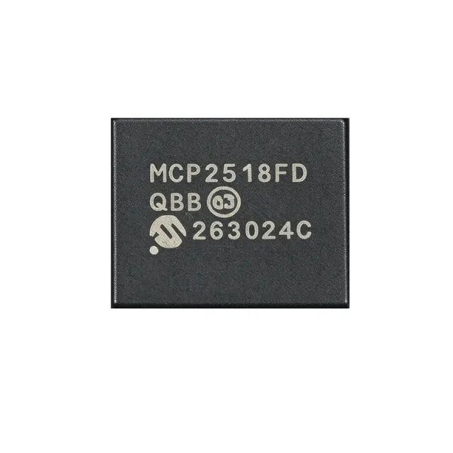
MCP2518FDT-E/QBB - CAN FD Controller, SPI, 14-VDFN | Microchip
MCP2518FDT-E/QBB

MCP2518FDT-E/QBB - CAN FD Controller, SPI, 14-VDFN | Microchip

The Microchip Technology MCP2518FDT-E/QBB is a stand-alone, low-power External CAN FD Controller with an SPI interface, housed in a 14-pin VDFN (4.5 mm x 3 mm) package with wettable flanks for automated optical inspection. It supports both Classical CAN 2.0B and CAN Flexible Data Rate (CAN FD) frames, enabling a cost-effective upgrade path for legacy CAN networks while delivering the higher payload and bit-rate advantages of CAN FD. The device integrates ECC-protected 2 KB RAM, dual maskable interrupt outputs, and grade-1 automotive temperature rating (-40C to +125C). A CAN FD Controller is a peripheral IC that handles the CAN/CAN FD protocol layer independent of the host microcontroller, exposing the bus as a register-mapped SPI slave. In the broader hierarchy, it sits above the physical-layer transceiver (such as the MCP2562FD) and below the application MCU; together these three blocks form a complete ISO 11898-1:2015 CAN node. Using an external controller lets designers add CAN FD to MCUs lacking an integrated CAN module, or offload protocol processing from low-power microcontrollers. Key features of the MCP2518FDT-E/QBB include up to 1 Mbit/s nominal CAN FD bit rate, 8 Mbit/s SPI clock support, low-power mode drawing approximately 10 µA typical, time-stamping via 32-bit TMR, and a wide operating voltage range of 2.7 V to 5.5 V. The VDFN-14 package occupies only 13.5 mm^2 of board area, making it the smallest CAN FD controller in Microchip's portfolio and ideal for space-constrained ECUs and sensor nodes. Architecturally, the MCP2518FD uses a dedicated CAN FD protocol engine plus RAM buffers, freeing the host MCU from bit-stuffing, arbitration, and CRC calculation. The SPI interface supports mode 0 and mode 3, with standard read/write commands plus a 16-bit CRC option on critical registers for EMI robustness. Combined with the external MCP2562FD high-speed transceiver, the resulting node is ISO 11898-1:2015 and ISO 11898-2:2016 compliant. Typical applications include automotive body and chassis networks, industrial CAN nodes (sensor hubs, motor drives), EV battery management (BMS) daisy chains, agricultural and off-highway vehicle telemetry, and any MCU-based system retrofitting CAN FD. The grade-1 (-40C to +125C) qualification makes it suitable for under-hood and chassis-mounted ECUs. When designing with this device, ensure the VDFN-14 exposed pad is soldered to a sufficiently large ground copper pour for thermal dissipation. A 100 nF decoupling capacitor must be placed within 5 mm of the VDD pin. The oscillator start-up time depends on the crystal load capacitance; consult the Microchip datasheet for matching network values. This page synthesizes distributor stock levels, parametric drop-in alternatives (including same-package Microchip variants), and PCB-layout guidance that is not consolidated on any single manufacturer or distributor product page.

USD $1.42 Dalam Stok
MCP2551-E - 1Mb/s High-Speed CAN Transceiver, ISO-11898 | Microchip
MCP2551-E

MCP2551-E - 1Mb/s High-Speed CAN Transceiver, ISO-11898 | Microchip

The Microchip Technology MCP2551-E is a high-speed, fault-tolerant CAN (Controller Area Network) transceiver that serves as the physical-layer interface between a CAN protocol controller and the differential CAN bus, capable of operating at data rates up to 1 Mb/s and fully compliant with the ISO-11898 standard including 24V bus requirements, housed in an 8-pin SOIC (SN) package. The device provides differential transmit and receive capability for the CAN protocol controller, with a single 5V supply input (4.5V to 5.5V), an internal slope-control pin for selectable baud-rate modes, and a low-power standby mode current of roughly 275 µA typ. A CAN transceiver is the analog physical-layer bridge of any CAN bus, sitting between a digital CAN controller (such as the MCP2515) and the actual twisted-pair wiring harness. Its primary job is to translate the controller's TXD/RXD CMOS logic into the dominant/recessive differential voltage levels defined by ISO-11898, while absorbing ESD strikes, bus shorts, and load-dump transients so the fragile controller is never exposed to them. As a category, CAN transceivers fall under interface ICs in the broader semiconductor taxonomy of standard logic and bus-interface devices. Key features of the MCP2551-E include three operating modes (high-speed, slope-control for lower EMI, and standby) selected via the RS pin, a transmitter capable of driving a worst-case 45-Ω load (corresponding to a heavily-loaded bus with 64 nodes), automatic thermal-shutdown protection, and bus fault tolerance meeting the 24V automotive requirement. The VREF pin supplies a 0.5 × VCC reference useful for stabilizing the recessive level. Architecturally, the die uses a bipolar driver stage for robust bus-side drive strength, with CMOS logic on the controller-side pins. The driver's output impedance and the on-chip slope-control current source are trimmed at the wafer level to give predictable rise/fall times across temperature, which is important in automotive under-hood environments where the bus length and capacitance can vary widely. Typical applications include in-vehicle networking (OBD-II, body controllers, instrument clusters), industrial CANopen and DeviceNet links, and any 5V microcontroller system needing a standard ISO-11898 CAN port. Designers often pair the MCP2551-E with the MCP2515 controller (the same Microchip family) for a complete CAN node. When designing with the MCP2551-E, always place a 100 nF decoupling capacitor close to VCC and provide a common-mode choke plus a 120 Ω termination resistor at each end of the bus. The part is now being superseded by the AEC-Q100-qualified MCP2561 for new automotive designs, but remains widely available and fully supported for industrial and legacy systems. This page consolidates Microchip datasheet specifications, drop-in SOIC-8 alternatives such as the MCP2561 and TI SN65HVD251, and field-level design guidance not found in a quick distributor lookup.

RFC Hubungi kami
MCP2551-E-P - 1 Mbps Fault-Tolerant CAN Transceiver
MCP2551-E-P

MCP2551-E-P - 1 Mbps Fault-Tolerant CAN Transceiver

The Microchip Technology MCP2551-E-P is a 1 Mbps high-speed CAN physical-layer transceiver with one transmitter and one receiver, a 4.5 V to 5.5 V supply range, and an 8-pin DIP package. It provides the physical interface between a CAN protocol controller and the differential CAN bus while supporting fault-tolerant operation in 12 V and 24 V systems. According to the supplied data, it implements ISO-11898 physical-layer requirements and uses externally controlled slope to reduce radio-frequency interference. A CAN transceiver is an interface IC that converts logic-level controller signals into the differential physical signaling used by a Controller Area Network. The MCP2551-E-P belongs to the hierarchy CAN transceiver > bus interface > interface IC > semiconductor. This device combines a CAN driver, CAN receiver, bus-fault handling, standby control, and a reference output in one physical-layer device. Its principal features include 1 Mb/s operation, one driver and one receiver, 4.5 V to 5.5 V operation, and suitability for 12 V and 24 V systems. Externally controlled slope is especially useful when electromagnetic compatibility must be balanced against bus timing. Fault tolerance is a core function because automotive and industrial CAN buses can experience wiring faults and abnormal bus conditions. The MCP2551-E/P designation identifies the through-hole 8-pin DIP format in the supplied distributor data. It is intended for designs using a CAN controller with a logic-side interface and a differential CANH/CANL bus connection. The package and protocol role make it relevant to automotive electronics, industrial automation, robotics, embedded control, and instrumentation. A key design consideration is that CAN bus implementation depends on correct termination, common-mode behavior, transceiver wiring, controller compatibility, and PCB or harness layout. The verified search data identifies the device as fault tolerant and capable of 1 Mb/s operation, but detailed loop-delay, propagation-delay, receiver-threshold, and absolute-maximum-rating values were not supplied. Those values should be taken from the manufacturer datasheet before final timing or protection design. This page synthesizes the supplied distributor and manufacturer-search data, package information, CAN use cases, replacement considerations, and practical design guidance. It does not infer undocumented electrical limits or assume regulatory compliance.

RFC Hubungi kami
MCP2551-E/SN - High-Speed CAN Transceiver 1Mbps SOIC-8 | Microchip
MCP2551-E-SN

MCP2551-E/SN - High-Speed CAN Transceiver 1Mbps SOIC-8 | Microchip

The Microchip Technology MCP2551-E/SN is a high-speed CAN (Controller Area Network) transceiver in an 8-pin SOIC (SN) package, providing the physical interface between a CAN protocol controller and the differential bus. It supports data rates up to 1 Mbps and is fully compatible with the ISO-11898-24V standard, including 24V bus fault protection. Operating from a single 4.5V to 5.5V supply, it is a 1/1 (one transmitter, one receiver) half-duplex transceiver. A CAN transceiver is the analog physical-layer device that converts the digital TX/RX logic signals from a CAN controller (such as the MCP2515) into the differential voltage levels required on a CAN bus. The CAN protocol itself is defined by ISO 11898 and is widely used in automotive (CAN, CAN-FD), industrial (CANopen, DeviceNet), and medical equipment because of its robust differential signaling, built-in arbitration, and reliable behavior in electrically noisy environments. Transceivers like the MCP2551 sit in the hierarchy: physical-layer transceiver -> CAN controller -> host MCU -> application layer. Key features include slope control for reduced EMI (selectable via the RS pin), a low-power standby mode (pin S1), thermal shutdown protection, short-circuit protection on the bus pins (CANH/CANL) to battery and ground, and an internal VREF output for biasing split termination. The device survives load-dump events up to ±40V on the bus pins, exceeding the ISO-7637 transient specification. Up to 112 nodes can be connected to a single CAN bus segment. Typical applications include automotive body and chassis networks, industrial CANopen and DeviceNet nodes, building automation (BACnet), fleet management and telematics, and any embedded system that needs ISO-11898-compliant differential CAN communication. The 5V VCC and 8-pin SOIC footprint also make it a convenient drop-in upgrade for legacy MCP2551 designs being migrated to longer lead-time alternatives. When designing with this device, place a 100nF decoupling capacitor close to VCC and use a split termination network (typically 120 ohm total with two 60 ohm resistors and a 10nF capacitor to ground) to match the bus impedance and suppress common-mode noise. Ensure the RS pin is tied to ground for high-speed mode or through a resistor to slow the slew rate if EMI is a concern.

RFC Hubungi kami
MCP2551-I - High-Speed CAN Transceiver, 1 Mb/s, 8-Pin DIP/SOIC | Microchip
MCP2551-I

MCP2551-I - High-Speed CAN Transceiver, 1 Mb/s, 8-Pin DIP/SOIC | Microchip

The Microchip Technology MCP2551-I is a high-speed CAN (Controller Area Network) fault-tolerant transceiver that interfaces a CAN protocol controller to the physical bus, operating at data rates up to 1 Mb/s in an 8-pin PDIP or SOIC package. It provides differential transmit and receive capability, is fully compatible with the ISO-11898 standard, and meets the 24V automotive bus requirement. The device supports a supply voltage range of 4.5V to 5.5V and is designed for harsh industrial and automotive environments. A CAN transceiver is a physical-layer device that translates the digital transmit/receive signals from a CAN controller into the differential voltage levels (CANH/CANL) required on the bus. It belongs to the broader hierarchy of interface ICs, sitting between protocol controllers (such as MCP2515 standalone CAN controllers) and the physical wiring harness, and ultimately forms part of the in-vehicle or industrial networking infrastructure. CAN transceivers like the MCP2551-I are the bedrock of automotive OBD-II, CANopen, and DeviceNet networks. Key features include ±80V bus fault protection on CANH and CANL, a high-noise immunity design (>1V common-mode range), thermal shutdown protection, and an automatic thermal slope control that reduces emissions at lower data rates. The device has three operating modes: High-Speed, Slope-Control, and Standby, with the mode selected via the RS pin. A VREF output (2.5V typical) is provided as a voltage reference for the CAN controller. The MCP2551-I uses a bipolar process technology and incorporates slope control to minimize EMI by limiting the rise/fall times of CANH and CANL. Its differential receiver provides excellent noise immunity with a typical hysteresis of 100 mV. The transceiver operates across -40°C to +125°C industrial temperature range, making it suitable for under-hood automotive and rugged industrial applications. Typical applications include automotive body and chassis networks, industrial CANopen and DeviceNet nodes, OBD-II vehicle diagnostics, HVAC and elevator control systems, and medical instrumentation interconnects. Designers frequently pair the MCP2551-I with the MCP2515 standalone CAN controller for full CAN node implementations. A critical design consideration is bus termination: the CAN bus requires 120 Ω resistors at each end of the bus segment, and these are typically not integrated in the MCP2551-I. The RS pin should be tied high through a resistor to VCC for high-speed operation or connected to ground through a resistor to enable slope-control mode for lower EMI at reduced data rates. This page synthesizes distributor pricing, drop-in alternatives, and practical design notes not found in the manufacturer datasheet alone, including cross-brand equivalents and pin-compatible migration paths to the MCP2561.

RFC Hubungi kami
MCP2551-I/P - 5V High-Speed CAN Transceiver DIP-8 | Microchip
MCP2551-I-P

MCP2551-I/P - 5V High-Speed CAN Transceiver DIP-8 | Microchip

The Microchip MCP2551-I/P is a high-speed CAN (Controller Area Network) protocol transceiver in an 8-pin PDIP (P) package, operating from a 4.5V to 5.5V single supply. It provides differential transmit and receive capability between a CAN protocol controller and the physical two-wire bus, supporting data rates up to 1 Mb/s per ISO-11898. The device includes slope-control input for selectable high-speed or slope-controlled (lower EMI) operation, a standby pin for low-power mode, and a VREF output for internal reference. A CAN transceiver is a physical-layer interface IC that bridges a digital CAN controller (typically a microcontroller with a CAN module) and the differential CAN bus wiring. It converts single-ended TXD logic into differential bus voltages on transmit, and converts differential bus voltages back into single-ended RXD logic on receive. CAN transceivers are the physical foundation of robust in-vehicle networking and industrial fieldbuses, and they are governed by the ISO 11898 family of standards. Key features of the MCP2551-I/P include: 1/1 (one driver, one receiver) half-duplex topology, 200 mV receiver hysteresis for noise immunity, thermal shutdown protection, short-circuit protection to battery and ground on the bus pins (up to ±40 V), and an operating temperature range of -40C to +85C (the "I" industrial grade). The device is widely deployed in automotive ECUs, industrial CAN nodes, building automation, and any embedded system that requires ISO 11898 compliant physical-layer connectivity. The MCP2551-I/P uses a bipolar architecture with internal slope control to limit EMI from the bus driver edge rates. The receiver inputs feature high common-mode range so the part tolerates ground offset between nodes. In addition, the device includes a VREF pin for a stable mid-supply reference voltage that older controllers require, making it a backwards-compatible choice for legacy CAN designs. Typical applications include automotive body and chassis ECUs, industrial CANopen and DeviceNet nodes, OBD-II diagnostic interfaces, agricultural machinery networks, and elevator or building automation controllers. Because the part is in a through-hole PDIP-8 package, it is also commonly used in prototyping, education kits, and hobby robotics (e.g. Arduino CAN shields) where through-hole assembly is preferred. When designing with the MCP2551-I/P, observe ISO 11898 bus termination requirements: a 120 ohm termination resistor at each end of the bus, twisted-pair cabling, and adequate common-mode choke or ESD protection for harsh environments. Also note that Microchip's newer MCP2561/2 family is the recommended migration path for new designs. This page synthesizes distributor pricing, drop-in alternatives, and practical design notes not found in the manufacturer datasheet.

RFC Hubungi kami
MCP2551-I/SN - High-Speed CAN Transceiver, 1Mb/s, ISO-11898 | Microchip
MCP2551-I-SN

MCP2551-I/SN - High-Speed CAN Transceiver, 1Mb/s, ISO-11898 | Microchip

The Microchip Technology MCP2551-I/SN is a high-speed Controller Area Network (CAN) protocol transceiver that serves as the interface between a CAN protocol controller and the physical differential bus, operating at speeds up to 1 Mb/s. The device is supplied from a single 4.5 V to 5.5 V rail, packaged in an 8-pin SOIC (SN) with industry-standard pinout, and provides differential transmit and receive capability to the bus. It is fully compatible with the ISO-11898 standard physical-layer requirements, including the 24 V load specification, making it suitable for both 12 V and 24 V automotive and industrial systems. A CAN transceiver is a physical-layer (PHY) device that converts the single-ended TTL-level transmit (TXD) and receive (RXD) signals of a CAN controller into the differential CAN_H and CAN_L signals driven on the bus. Transceivers such as the MCP2551 provide the dominant/recessive arbitration signaling, bus biasing, ESD protection, and fault tolerance needed by the differential multi-drop CAN bus used in automotive and industrial networking. They sit between the bus and protocol controllers such as the Microchip MCP2515 or the MCU-integrated CAN modules on dsPIC, PIC18, and many ARM Cortex-M microcontrollers. Key features of the MCP2551-I/SN include 1 Mb/s maximum data rate, externally-controlled slope (rise/fall) adjustment for reduced RFI, a low-current standby mode, a VREF output for the CAN controller's input reference, and detection of permanent bus dominant faults with automatic recovery to receiver-only mode. The device also supports the -2 V to +7 V common-mode range required by ISO-11898-2 (extended common-mode versions go further) and includes thermal shutdown and current limiting on the bus pins for bus-fault protection. Architecturally, the MCP2551 uses an NMOS differential driver on the bus side with slope control implemented by varying the driver output current; a bandgap-based VREF generator provides a 2.5 V (typical) reference for the RXD comparator threshold generation inside the controller. Internal hysteresis and input filtering suppress RF and transient noise on CAN_H/CAN_L without delaying the bit time, which preserves CAN arbitration timing at the maximum 1 Mb/s data rate. Typical applications include automotive body and powertrain networks, industrial CAN-based control systems (CANopen, DeviceNet, NMEA 2000), building automation, HVAC controls, and any embedded design using a Microchip MCU with a CAN module. Its 8-SOIC footprint and 5 V supply make it easy to add a CAN physical layer to existing 5 V designs. Note: per Microchip's discontinuance notices, the MCP2551 in SOIC-8 (SN) is being phased out, so verify stock and review the recommended MCP2561/2562 successor family for new designs. When designing with this device, observe CAN bus termination: place 120 ohm resistors at each END of the bus (not at every node), and use twisted-pair cabling. Provide a small decoupling capacitor as close as possible to VDD (pin 3) and tie the unused RS pin (pin 8) to GND through a resistor (or directly) to select normal high-speed slew rate. This page synthesizes distributor pricing, drop-in alternatives, and practical PCB/CAN-bus design notes not found in a single manufacturer datasheet.

RFC Hubungi kami
MCP2551T-E/SN - 1Mbps Fault-Tolerant CAN | Microchip
MCP2551T-E/SN

MCP2551T-E/SN - 1Mbps Fault-Tolerant CAN | Microchip

The Microchip Technology MCP2551T-E/SN is a high-speed, fault-tolerant CAN transceiver operating up to 1 Mb/s, supplied from 4.5 V to 5.5 V and housed in an 8-pin SOIC package. It provides one differential CAN driver and one differential receiver, forming the physical-layer interface between a CAN protocol controller and a 12 V or 24 V CAN bus. The device supports the ISO-11898 physical-layer requirements, including the stated 24 V requirement, and its industry-standard 8-SOIC pinout supports surface-mount PCB assembly. A CAN transceiver, also called a CAN physical-layer interface, converts logic-level TXD and RXD signals into the dominant and recessive voltage states used on a differential CAN network. It bridges a host CAN controller and the physical bus while providing fault-tolerant behavior for automotive, industrial, and embedded systems. The MCP2551 family is positioned above simple logic transceivers because it addresses bus termination, common-mode operation, radiated emissions, and protection in connected vehicle or machine environments. Key verified features include support for 1 Mb/s operation, differential transmit and receive, ISO-11898 physical-layer compatibility, suitability for 12 V and 24 V systems, and externally controlled slope for reduced RFI emissions. The supplied datasheet also describes ground-fault detection for a permanent dominant condition on the TXD input. These features help a system control edge rate, recognize abnormal bus states, and reduce electromagnetic interference while retaining a conventional controller interface. The MCP2551 is a 1/1 CAN transceiver: one driver and one receiver are combined in one package. Its 4.5 V to 5.5 V supply range matches conventional 5 V CAN-controller ecosystems. At the physical bus, the differential CANH and CANL conductors carry complementary signals, while the transceiver interfaces to the controller through TXD and RXD. The exact logic levels, propagation delays, receiver thresholds, and absolute maximum ratings should be read from the manufacturer datasheet before final sign-off. Typical uses include automotive diagnostic links, industrial automation equipment, elevator and building-control networks, robotics, embedded motor-control systems, and CAN-based sensor or actuator networks. The 1 Mb/s capability is appropriate for high-rate short CAN networks, while the external slope-control option allows the designer to tune emissions behavior to the PCB and cabling environment. The 8-SOIC package also makes the device convenient for surface-mount designs that need a separate physical-layer transceiver beside a host microcontroller. Designers should pay attention to bus termination, transceiver supply decoupling, common-mode grounding, and the CAN controller's timing requirements. Place the termination network at the physical ends of the bus rather than beside every node. Review the datasheet's TXD, RXD, VDD, GND, CANH, and CANL connections and verify the selected logic family and package variant before manufacture. The MCP2551T-E/SN data should be treated as the authoritative source for values not explicitly stated in the verified search results. This page consolidates the verified MCP2551T-E/SN specifications, source links, application guidance, and replacement considerations. Pricing is shown as reference data as of 2026-10-22 where supplied by the verified distributor result; current commercial availability should be confirmed directly with the seller.

RFC Hubungi kami
MCP2551T-I/SN - 1 Mb/s CAN Transceiver | Microchip
MCP2551T-I/SN

MCP2551T-I/SN - 1 Mb/s CAN Transceiver | Microchip

The Microchip Technology MCP2551T-I/SN is a 1 Mb/s high-speed CAN transceiver operating from a 4.5 V to 5.5 V supply in an 8-pin SOIC package. It provides one differential transmitter and one differential receiver between a CAN protocol controller and the physical CAN bus, with fault tolerance and compatibility with ISO-11898 requirements, including 24 V bus conditions. Its 5 V interface and 8-SOIC construction suit conventional embedded CAN nodes requiring a direct logic-side transceiver connection. A CAN transceiver is the physical-layer interface between a CAN controller and a multidrop differential bus. The controller generates and interprets CAN frames, while the transceiver converts controller logic into dominant and recessive differential states and converts bus differential voltage into a readable receive signal. This separation allows a microcontroller or dedicated CAN controller to implement the protocol while the MCP2551 handles bus-level voltage, noise immunity, and fault containment. Key verified characteristics include differential transmit and receive, operation up to 1 Mb/s, a 4.5 V to 5.5 V supply range, ISO-11898 compatibility including 24 V requirements, and fault-tolerant operation. The T-I/SN ordering code identifies the 8-pin SOIC, industrial-temperature, tape-and-reel ordering configuration; the verified distributor result describes the device as one transmitter and one receiver in an 8-SOIC package. The MCP2551 family is suitable for industrial automation, automotive electronics, embedded control, instrumentation, and other CAN networks operating with a 5 V transceiver supply. Designers should still validate the complete system against its required ISO-11898 revision, bus topology, termination, fault behavior, EMC requirements, and controller timing. The manufacturer datasheet is the controlling source for absolute maximum ratings, DC and AC electrical characteristics, timing, dimensions, and detailed application guidance. Use a 5 V regulated transceiver rail, connect the controller TXD and RXD pins according to the datasheet, and terminate the differential bus at both physical ends with the resistance specified by the selected bus standard. Keep the CANH and CANL routing as a controlled differential pair, provide a solid ground reference, and avoid long unprotected stubs. Decoupling should follow the manufacturer recommendations and be placed close to the supply pins. The key engineering trade-off is that this is a classic 5 V SOIC transceiver rather than a smaller, lower-voltage or automotive-packaged alternative. The result is useful because it combines a straightforward controller interface, established CAN physical-layer behavior, and compact 8-pin packaging. This page consolidates verified source links, commercial availability information, replacement constraints, and practical PCB guidance that should be checked against the latest manufacturer documentation before release to production.

RFC Hubungi kami
MCP2562-E/SN - 1Mbps CAN Transceiver, 5V | Microchip
MCP2562-E/SN

MCP2562-E/SN - 1Mbps CAN Transceiver, 5V | Microchip

The Microchip Technology MCP2562-E/SN is a 1 Mbps high-speed CAN transceiver with a 4.5 V to 5.5 V supply range and an 8-pin SOIC package. It provides one CAN transmitter and one CAN receiver, bridging a CAN protocol controller to a physical two-wire CAN bus. A dedicated VIO supply supports direct interfacing with microcontrollers operating from 1.8 V to 5.5 V. A CAN transceiver is an interface IC that converts logic-level controller signals into the dominant and recessive voltage states used on a CAN bus, while converting bus states back into controller-compatible receive data. The MCP2562 family is commonly used in the CAN interface layer between a host microcontroller, CAN controller, vehicle network, industrial automation system, or embedded diagnostic equipment. The verified product information identifies the MCP2562-E/SN as a 1 Mbps CAN transceiver with a 5 V operating supply and an 8-pin SOIC package. Its separate VIO pin reduces the need for external level shifters when the CAN controller uses a lower-voltage IO domain. The device also supports standby control and undervoltage-related bus-management functions according to the product description sources. The MCP2562-E/SN is suitable for high-speed CAN networks requiring a compact surface-mount solution. Its 1 Mbps data rate supports automotive and industrial communication systems, while the dedicated VIO supply helps simplify connections to modern low-voltage microcontrollers. The 8-SOIC package also facilitates conventional PCB assembly and inspection. Typical applications include automotive engine-control modules, body electronics, industrial controllers, robotics, CAN-based sensor networks, diagnostic equipment, and embedded communication gateways. Designers should verify pin compatibility, transceiver mode behavior, supply sequencing, bus termination, and EMC requirements before replacing another CAN transceiver. This page combines verified distributor and manufacturer-derived product facts, structured specifications, application guidance, design notes, and same-footprint alternatives. Exact operating-temperature limits, loop-delay values, ESD ratings, and pin-level electrical limits require confirmation from the manufacturer datasheet before design release.

RFC Hubungi kami
MCP2562FD-E/SN - CAN FD Transceiver, 8-SOIC | Microchip
MCP2562FD-E/SN

MCP2562FD-E/SN - CAN FD Transceiver, 8-SOIC | Microchip

The Microchip Technology MCP2562FD-E/SN is a second-generation high-speed CAN Flexible Data Rate (CAN FD) transceiver that interfaces a CAN protocol controller to the physical two-wire CAN bus, housed in an 8-pin SOIC (SN) package. It supports data rates up to 8 Mbps in CAN FD mode, 5 Mbps in classic CAN mode with high-speed slew rate, and operates over a VIO supply range of 1.8V to 5.5V for direct MCU interface. Key features include a maximum loop delay of 130 ns and guaranteed loop delay symmetry to support CAN FD bit timing requirements. The device operates across an ambient temperature range of -40C to +125C and survives load dump transients up to +/- 70V on the bus pins through integrated protection. A CAN transceiver serves as the physical-layer interface between a CAN protocol controller (such as the MCP2518FD or integrated CAN module on a microcontroller) and the differential CAN bus (CANH/CANL). It translates the controller's transmit (TXD) and receive (RXD) digital logic into the differential bus signaling defined by ISO 11898-2:2016, and provides the dominant and recessive states needed for non-destructive bitwise arbitration. CAN FD extends the classic CAN payload from 8 bytes to 64 bytes while remaining backward-compatible at the physical layer, which is why FD-compliant transceivers like the MCP2562FD are now preferred even for classic CAN designs. The MCP2562FD delivers 5 key advantages. First, the integrated VIO pin eliminates level shifters when interfacing 1.8V/3.3V MCUs. Second, low loop-delay symmetry (<=130 ns total) enables reliable 2 Mbps and 5 Mbps CAN FD operation. Third, +/- 36V receiver common-mode range tolerates large ground shifts across nodes. Fourth, +/- 70V bus-pin transient protection (IEC 61000-4-2 ESD and load dump) eliminates external TVS diodes in most automotive 12V/24V systems. Fifth, an ultra-low-current standby mode (~15 uA typical) preserves battery life in always-bus-wake applications. The MCP2562FD uses a 1.8V to 5.5V VIO supply rail that sets the logic level reference for TXD, RXD, and the standby (STBY) pin, while the VCC/VSUP rail (4.5V to 5.5V) powers the bus-side driver. An on-chip LDO from VCC to VIO is provided on the -H variants; the -E/SN variant requires the user to supply VIO externally for maximum flexibility. The integrated slope-control circuitry automatically adjusts the CANH/CANL edge rate to meet ISO 11898-2:2016 at any speed between 50 kbps and 5 Mbps, so no external resistor selection is required. Typical applications include automotive gateway ECUs, body-control modules, ADAS sensor CAN buses, industrial PLC networking, agricultural machinery CAN backbones, and any battery-powered remote sensor that needs an always-listening low-power mode. It also suits prototypes and maker projects using boards such as the Teensy, Arduino, and Raspberry Pi that need a CAN shield with simple 3.3V logic. When designing with this device, route the CANH/CANL traces as a 120-ohm differential pair with characteristic impedance of 120 ohms and place a 120-ohm termination resistor at each end of the bus; place a 100 nF decoupling capacitor as close as possible to the VCC and VIO pins to suppress switching noise from the bus driver. This page synthesizes distributor pricing, drop-in cross-brand alternatives, and practical layout guidance not found in the manufacturer datasheet.

RFC Hubungi kami
MCP3001-I/MS - 10-Bit SPI ADC | Microchip Technology
MCP3001-I/MS

MCP3001-I/MS - 10-Bit SPI ADC | Microchip Technology

The Microchip Technology MCP3001-I/MS is a 10-bit, single-input successive-approximation-register analog-to-digital converter with a 200 ksample/s sampling rate, SPI serial interface, and 8-pin MSOP package. It is designed for embedded control systems that require a compact, low-power analog measurement input. An analog-to-digital converter is an interface IC that converts a continuously varying voltage into a numeric value for processing by a microcontroller or other digital controller. The MCP3001 belongs to the SAR ADC family and the broader ADC and data-converter hierarchy. Its internal sample-and-hold function, SPI interface, and low-power characteristics support efficient acquisition in temperature sensing, industrial measurement, and general embedded control equipment. Key features include 10-bit resolution, one analog input channel, a 200 ksample/s conversion rate, and compatibility with SPI modes 0,0 and 1,1. The manufacturer documentation identifies maximum DNL and INL of ±1 LSB. The -I grade ordering code denotes Microchip's industrial temperature grade, although the exact numerical temperature limits are not present in the supplied web data and therefore require confirmation from the datasheet before use. The MCP3001 uses a successive-approximation conversion architecture. A conversion is initiated after chip select is asserted, and the ADC samples the selected analog input while communicating successive conversion information over the serial interface. The host processor supplies the command bits, reads the converted result, and controls the sampling sequence. This architecture is appropriate when conversion speed, interface simplicity, and low system cost matter more than the throughput or channel count of a higher-performance ADC. Typical uses include digital thermometers, environmental sensors, process-control instrumentation, battery monitoring, laboratory measurement equipment, and embedded analog front ends. The single SPI-compatible channel also makes the device useful in compact designs where a microcontroller has adequate timer and serial-port resources for chip-select handling and clock generation. When designing a PCB for the MCP3001-I/MS, place the device close to the analog source and route the analog input away from noisy switching nodes and high-current traces. Provide a clean reference voltage, confirm the input range against the chosen supply voltage, and keep the SPI traces short. Review the datasheet for the exact recommended input and reference-decoupling network rather than assuming that generic bypass values are sufficient.

RFC Hubungi kami