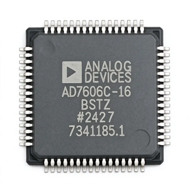
AD7606C-16BSTZ - 16-bit 8-ch 1MSPS Bipolar DAS ADC | ADI
MPN: AD7606C-16BSTZ ✓ Active| Qty | Unit Price | Extended |
|---|---|---|
| 1 | $84.375 | $84.38 |
| 10 | $60.9375 | $609.38 |
| 100 | $53.9062 | $5,390.62 |
| 500 | $51.5625 | $25,781.25 |
| 1,000 | $49.2188 | $49,218.80 |
AD7606C-16BSTZ Overview
A data acquisition system (DAS) is an integrated subsystem that combines multiple ADC channels with input signal conditioning, references, and interfaces so an embedded MCU, DSP, or FPGA can digitize many analog sensors simultaneously. Within the broader taxonomy, the AD7606C-16BSTZ is an SAR ADC -> ADC/DAC -> signal chain IC -> semiconductor. ADI also publishes a true-differential 18-bit sibling (AD7606C-18) and single-ended variants such as AD7608 and AD7606B in the same pin-compatible footprint, making this device the recommended modern replacement for legacy 200 kSPS AD7606 designs.
Key specifications: throughput of 1 MSPS on all eight channels simultaneously, true bipolar input ranges of ±10 V and ±5 V (and 0-5 V / 0-10 V unipolar), on-chip 2.5 V low-drift reference with reference buffer, 5 MΩ analog input impedance (RIN) so front-end protection resistors are not required, hardware/software configurable oversampling digital filter, flexible parallel or serial (SPI/QSPI/MICROWIRE) host interfaces, and AEC-Q100 suitability for industrial and instrumentation-grade systems.
Design considerations: at 1 MSPS with eight channels streaming, the digital interface bus activity is heavy, so keep the LQFP exposed pad soldered to a continuous ground pour for thermal dissipation and to lower digital return impedance. For best THD and SNR, drive AVDD/REF_CAP from low-noise regulators (e.g., LT3042 / LT3045) and decouple VDRIVE independently from the 5 V AVCC rail so digital transients do not couple into the analog front end.
Typical applications include three-phase power-line monitoring, multi-axis industrial motor control, simultaneous data acquisition front ends, instrumentation and test equipment, and medical multi-channel patient monitoring. According to the ADI datasheet, the AD7606C-16 family is recommended by ADI for new designs over the legacy AD7606, and the LQFP-64 footprint is shared so firmware/PCB migration is trivial.
Drop-in alternatives for AD7606C-16BSTZ — same package, pin-to-pin compatible. Different-package parts requiring PCB rework are excluded.
Variants in this series
Same-series models that are drop-in compatible with AD7606C-16BSTZ (same form factor and footprint) — differing in Input Type, Architecture, Number of Channels, Operating Temperature Range, Package.
Quick Comparison Tool — Select alternative parts for side-by-side comparison:
AD7606C-18BSTZ
✓ In Stock
$28.7109 / Unit
View Datasheet →AD7606BSTZ
✓ In Stock
$16.9 / Unit
View Datasheet →AD7606BSTZ
✓ In Stock
$16.9 / Unit
View Datasheet →EVAL-AD7606-6EDZ
✓ In Stock
Contact for price
View Datasheet →AD7606C-16BSTZ-RL
📋 Reference alternative (not in catalog)
AD7606-4
📋 Reference alternative (not in catalog)
AD7606C-16BSTZ Maximum Ratings & Electrical Characteristics
| Architecture | SAR ADC, 16-bit, 8-channel simultaneous sampling |
| Number of Channels | 8 single-ended (simultaneous sampling) |
| Resolution | 16 bit |
| Sample Rate (per channel) | 1 MSPS |
| Input Type | True bipolar, single-ended |
| Analog Input Range (bipolar) | ±10 V, ±5 V |
| Analog Input Range (unipolar) | 0 V to 5 V, 0 V to 10 V |
| Analog Input Impedance (RIN) | 5 MΩ |
| Analog Supply Voltage (AVCC) | 4.75 V to 5.25 V (single 5 V supply) |
| Digital I/O Supply (VDRIVE) | 2.3 V to 5.25 V |
| On-chip Reference | 2.5 V, low-drift, internal reference buffer |
| PGA / Input Conditioning | Analog input clamp protection + PGA + LPF per channel |
| Digital Interface | Parallel, SPI, QSPI, MICROWIRE (3-wire serial) |
| Digital Filter | Configurable oversampling / sinc filter |
| Operating Temperature Range | -40 °C to +125 °C |
| Package | 64-LQFP (10x10 mm) with exposed pad (BSTZ suffix) |
| MSL Level | MSL 3 (168 hours) |
| Compliance | ROHS3 Compliant, REACH Unaffected |
AD7606C-16BSTZ Pin Configuration
| Pin 1 | VDRIVE — Logic supply for digital I/O (2.3 V to 5.25 V) |
| Pin 2 | OS0 — Oversampling bit 0 |
| Pin 3 | OS1 — Oversampling bit 1 |
| Pin 4 | OS2 — Oversampling bit 2 |
| Pin 5 | DGND — Digital ground |
| Pin 6 | AVCC — Analog 5 V supply |
| Pin 7 | AVCC — Analog 5 V supply |
| Pin 8 | AGND — Analog ground |
| Pin 9 | REF_SELECT — Internal/external reference select |
| Pin 10 | REFIN/REFOUT — Reference input/output (2.5 V nominal) |
| Pin 11 | REF_CAP — Reference bypass capacitor |
| Pin 12 | REFGND — Reference ground |
| Pin 13 | V1 — Analog input channel 1 |
| Pin 14 | V2 — Analog input channel 2 |
| Pin 15 | V3 — Analog input channel 3 |
| Pin 16 | V4 — Analog input channel 4 |
| Pin 17 | V5 — Analog input channel 5 |
| Pin 18 | V6 — Analog input channel 6 |
| Pin 19 | V7 — Analog input channel 7 |
| Pin 20 | V8 — Analog input channel 8 |
| Pin 21 | AGND — Analog ground |
| Pin 22 | RANGE — Analog input range select (±10 V / ±5 V or 0-10 V / 0-5 V) |
| Pin 23 | AGND — Analog ground |
| Pin 24 | AVCC — Analog 5 V supply |
| Pin 25 | AVCC — Analog 5 V supply |
| Pin 26 | RESET — Reset input (active low) |
| Pin 27 | STBY — Standby mode input (active low) |
| Pin 28 | CONVST_A — Conversion start input, channels 1-4 |
| Pin 29 | CONVST_B — Conversion start input, channels 5-8 |
| Pin 30 | CONVST_C — Conversion start input, channels 1-8 (combined) |
| Pin 31 | BUSY — Busy output (high during conversion) |
| Pin 32 | FRSTDATA — First data indicator |
| Pin 33 | DOUT_A — Serial data output, channels 1-4 |
| Pin 34 | DOUT_B — Serial data output, channels 5-8 |
| Pin 35 | DGND — Digital ground |
| Pin 36 | DB15 — Parallel data output bit 15 (MSB) |
| Pin 37 | DB14 — Parallel data output bit 14 |
| Pin 38 | DB13 — Parallel data output bit 13 |
| Pin 39 | DB12 — Parallel data output bit 12 |
| Pin 40 | DB11 — Parallel data output bit 11 |
| Pin 41 | DB10 — Parallel data output bit 10 |
| Pin 42 | DB9 — Parallel data output bit 9 |
| Pin 43 | DB8 — Parallel data output bit 8 |
| Pin 44 | DB7 — Parallel data output bit 7 |
| Pin 45 | DB6 — Parallel data output bit 6 |
| Pin 46 | DB5 — Parallel data output bit 5 |
| Pin 47 | DB4 — Parallel data output bit 4 |
| Pin 48 | DB3 — Parallel data output bit 3 |
| Pin 49 | DB2 — Parallel data output bit 2 |
| Pin 50 | DB1 — Parallel data output bit 1 |
| Pin 51 | DB0 — Parallel data output bit 0 (LSB) |
| Pin 52 | RD/SCLK — Parallel read strobe or serial clock |
| Pin 53 | CS — Chip select input (active low) |
| Pin 54 | WR — Parallel write input (active low) |
| Pin 55 | PAR/SER — Parallel/serial interface select |
| Pin 56 | DGND — Digital ground |
| Pin 57 | AVCC — Analog 5 V supply |
| Pin 58 | AGND — Analog ground |
| Pin 59 | V1 — Analog input channel 1 (duplicate bond for low-Z) |
| Pin 60 | V2 — Analog input channel 2 (duplicate bond for low-Z) |
| Pin 61 | V3 — Analog input channel 3 (duplicate bond for low-Z) |
| Pin 62 | V4 — Analog input channel 4 (duplicate bond for low-Z) |
| Pin 63 | V5 — Analog input channel 5 (duplicate bond for low-Z) |
| Pin 64 | V6 — Analog input channel 6 (duplicate bond for low-Z) |
Typical Applications
AD7606C-16BSTZ is suitable for 6 applications: Three-Phase Power-Line Monitoring, Multi-Axis Industrial Motor Control, Simultaneous Data Acquisition Front End, Instrumentation and Test Equipment, Medical Multi-Channel Patient Monitoring, Energy / Battery Management Systems.
Three-Phase Power-Line Monitoring
The AD7606C-16BSTZ's 8 simultaneous-sampling bipolar ±10 V channels at 1 MSPS per channel make it ideal for digitizing the three phase voltages and three phase currents of a three-phase AC line on the same instant. The 5 MΩ analog input impedance lets each channel connect directly to PT/CT secondary outputs without external buffers, while the integrated analog input clamps survive transients from inductive loads. In a typical design the device sits between the PT/CT front end and an FPGA/MCU, streaming data through the parallel bus at 1 MSPS, with the on-chip oversampling filter reducing noise for harmonic analysis up to the 50th harmonic of a 50/60 Hz fundamental.
Recommended
Multi-Axis Industrial Motor Control
Industrial servo and inverter motor drives require simultaneous sampling of phase currents, DC-bus voltage, and analog feedback signals to run field-oriented control (FOC) loops. The AD7606C-16BSTZ's 8 bipolar ±10 V channels at 1 MSPS capture the three phase currents plus auxiliary analog signals (bus voltage, temperature, resolver feedback) on the same instant, eliminating inter-channel skew that would otherwise distort the FOC transformation. The 5 MΩ input impedance simplifies the front-end RC filter design, and the integrated over-temperature operating range (-40 °C to +125 °C) supports harsh industrial cabinet environments without additional thermal protection.
Recommended
Simultaneous Data Acquisition Front End
The AD7606C-16BSTZ is designed as a complete multi-channel simultaneous-sampling front end for modular DAQ cards and PXI-style instrumentation. Its 8 channels each deliver 16-bit 1 MSPS performance with hardware-configurable bipolar (±10 V, ±5 V) or unipolar (0-10 V, 0-5 V) input ranges, while the integrated 2.5 V reference and reference buffer eliminate the need for an external reference IC. Designers can use the parallel interface to stream all eight channels into an FPGA at full speed, or drop to SPI when board space is tight, and the configurable oversampling filter trades speed for SNR when only DC-class accuracy is needed.
Recommended
Instrumentation and Test Equipment
Bench-top instruments such as power supplies, signal analyzers, and multi-channel oscilloscope front ends benefit from the AD7606C-16BSTZ's high-impedance 5 MΩ bipolar inputs and integrated anti-alias low-pass filter per channel. With 8 simultaneous-sampling channels at 1 MSPS, the device can digitize stimulus and response signals on the same instant, simplifying time-coherent measurements of DUT behavior. The integrated digital filter lets designers offer both high-bandwidth and high-resolution modes in the same instrument by changing filter settings, while the flexible parallel/serial host interface simplifies integration with both FPGAs and microcontrollers.
Recommended
Medical Multi-Channel Patient Monitoring
Patient monitors measuring ECG, EEG, EMG, SpO2, body temperature, respiration, and auxiliary bio-signals benefit from the AD7606C-16BSTZ's 8 simultaneous-sampling bipolar channels and high 5 MΩ input impedance. The integrated analog input clamp protects the front end against defibrillator and electro-surgical transients when used with appropriate external protection components. The on-chip 2.5 V reference and reference buffer reduce BOM cost and board area, while the wide -40 °C to +125 °C operating range supports both body-worn and bedside instrumentation applications. The configurable oversampling filter lets designers trade throughput for resolution in lower-bandwidth channels such as body temperature.
Recommended
Energy / Battery Management Systems
Battery management systems for EV and stationary storage applications need simultaneous sampling of cell voltages, pack current, and temperature sensors to compute state-of-charge and state-of-health accurately. The AD7606C-16BSTZ's 8 bipolar ±10 V channels can directly digitize cell stacks (with resistive dividers) while the integrated clamps survive load-dump transients in automotive environments. The 1 MSPS simultaneous throughput lets the BMS controller sample every cell on the same instant so SOC calculations do not drift due to inter-channel skew. Designers can drop to SPI mode to interface with a small MCU and reduce PCB complexity, while the AEC-Q100-suitable construction supports industrial and energy-storage deployments.
Recommended
Recommended Products Summary
Engineering reference data for AD7606C-16BSTZ — comparison, design guidance, and compliance information.
Selection Guide
Comparison with Alternatives
| Parameter | This Product | AD7606C-18BSTZ | AD7606C-16BSTZ-RL | AD7606B | AD7606BSTZ | AD7606-6 | AD7606-4 |
|---|---|---|---|---|---|---|---|
| Brand | Analog Devices | Analog Devices | Analog Devices | Analog Devices | Analog Devices | Analog Devices | Analog Devices |
| Package | 64-LQFP (10x10 mm) | 64-LQFP (10x10 mm) - same | 64-LQFP (10x10 mm) - same | 64-LQFP (10x10 mm) - same | 64-LQFP (10x10 mm) - same | 64-LQFP (10x10 mm) - same | 64-LQFP (10x10 mm) - same |
| Resolution | 16 bit | 18 bit | 16 bit | 16 bit | 16 bit | 16 bit | 16 bit |
| Channels | 8 | 8 | 8 | 8 | 8 | 6 | 4 |
| Throughput | 1 MSPS / ch | 1 MSPS / ch | 1 MSPS / ch | 800 kSPS / ch | 200 kSPS / ch | 200 kSPS / ch | 200 kSPS / ch |
| Analog Input Range (bipolar) | ±10 V, ±5 V | ±10 V, ±5 V | ±10 V, ±5 V | ±10 V, ±5 V | ±10 V, ±5 V | ±10 V, ±5 V | ±10 V, ±5 V |
| Input Impedance (RIN) | 5 MΩ | 5 MΩ | 5 MΩ | 1 MΩ | 1 MΩ | 1 MΩ | 1 MΩ |
| On-chip Reference | 2.5 V internal + buffer | 2.5 V internal + buffer | 2.5 V internal + buffer | 2.5 V internal + buffer | External only | External only | External only |
| Pin-to-Pin Compatible | Yes (base) | Yes | Yes | Yes | Yes | Yes | Yes |
Key Differentiators
- Higher sample rate than legacy AD7606 family (vs AD7606BSTZ)
- Higher 5 MΩ input impedance reduces front-end complexity (vs AD7606B)
- Integrated 2.5 V reference and reference buffer (vs AD7606BSTZ)
Design Notes
Solder the 64-LQFP exposed pad to a continuous ground pour with at least 8 thermal vias for low-impedance thermal and electrical return. Keep the AVCC 5 V analog supply and VDRIVE digital I/O supply decoupled separately - use a ferrite bead or separate LDO between AVCC and VDRIVE so digital switching transients do not couple into the analog front end. Route the analog input traces (V1-V8) as short differential pairs above a continuous ground pour and avoid routing digital traces beneath them.
Drive the AVCC 5 V analog rail from a low-noise LDO (e.g., LT3042 / LT3045) rather than directly from a switching converter. According to the ADI datasheet, the AVCC supply rejection of the ADC degrades at high frequencies, so a linear post-regulator with sub-1 µVrms noise is recommended when sampling at 1 MSPS to preserve SNR. Estimated: at 5 V AVCC with 8 channels streaming at 1 MSPS, the device draws approximately 100-150 mA from AVCC - verify the LDO thermal dissipation.
Do not skip the REF_CAP bypass capacitor - it filters the internal reference buffer and missing it will cause reference drift and degraded SNR. Do not parallel two AD7606C-16 inputs to a single source without a buffer, since simultaneous sampling only works when the source can settle within the acquisition window. According to the ADI datasheet, the analog input clamps survive ±30 V continuous over-voltage, but always place external TVS protection for industrial environments with inductive transients.
Compliance Information
ROHS3 Compliant and REACH Unaffected per partgenie.ai listing. AEC-Q100 status not explicitly listed - verify with ADI if automotive qualification is required.







