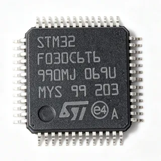
FS32K144WAT0WLFT - S32K144 80MHz 512KB Flash MCU | NXP
MPN: FS32K144WAT0WLFT ✓ Active| Qty | Unit Price | Extended |
|---|---|---|
| 1 | $11.5 | $11.50 |
| 10 | $7.71 | $77.10 |
| 25 | $7.47 | $186.75 |
| 100 | $7.24 | $724.00 |
| 250 | $7.23 | $1,807.50 |
| 500 | $7.01 | $3,505.00 |
FS32K144WAT0WLFT Overview
A microcontroller (MCU) is an integrated circuit that combines a CPU core, program and data memory, peripherals, and I/O on a single silicon die. Within the broader semiconductor hierarchy, an MCU is a sub-class of microcontroller -> embedded processor -> SoC -> semiconductor device. The S32K1 family further specializes in automotive-grade general-purpose MCUs (GPMs) that meet AEC-Q100 Grade 1/2 qualification, distinguishing it from industrial Cortex-M parts. The M4F core variant adds a single-precision Floating-Point Unit, easing signal-processing and sensor-fusion workloads.
Key features include 64 KB SRAM, a 12-bit 1 Msps ADC with up to 16 channels, multiple timer modules (FlexTimer, eMIOS), and rich connectivity through CAN FD, LIN, SPI, UART, and I2C. The CSEc engine provides secure boot, key storage, and AES-128 acceleration, while a separate Cortex-M0+ core on select variants handles hardware security. Wide supply range (2.7 V to 5.5 V) supports both 3.3 V and 5 V automotive rails.
The S32K144 architecture uses low-power modes (Halt, Stop, Run) with rapid wake-up via the ARM WFI/WFE instructions, enabling ECUs that draw <30 µA in standby while still supporting CAN wake-up. On-chip memory includes ECC on Flash and SRAM for ASIL-B functional safety support per ISO 26262. The device is qualified to AEC-Q100 Grade 1 (-40°C to +125°C), making it suitable for under-hood and body-domain modules.
Typical applications include automotive body control modules (BCM), lighting controllers, seat and mirror modules, HVAC interfaces, CAN/LIN gateway nodes, and small sensor ECUs. Its combination of CAN FD, CSEc, and AEC-Q100 reliability targets the modern vehicle network where encrypted, low-latency communication and deterministic behavior are required.
When designing with the FS32K144WAT0WLFT, ensure the chosen variant includes the peripherals your firmware expects - the LQFP-48 footprint limits exposed peripheral counts versus the LQFP-64 or LQFP-100 packages. Use the S32K1 SDK and configuration tools (S32 Config Tools, EB tresos) to validate pin allocation and peripheral routing before layout.
This page synthesizes distributor pricing, parametric cross-reference data, and practical design notes for the FS32K144WAT0WLFT not found in the bare manufacturer datasheet.
Drop-in alternatives for FS32K144WAT0WLFT — same package, pin-to-pin compatible. Different-package parts requiring PCB rework are excluded.
Quick Comparison Tool — Select alternative parts for side-by-side comparison:
FS32K144WAT0WLHR
✅ Drop-In ⚠️ Specs Unverified📋 Reference alternative (not in catalog)
FS32K144HAT0MLHR
✅ Drop-In ⚠️ Specs Unverified📋 Reference alternative (not in catalog)
FS32K144WFT0WLFT
✅ Drop-In ⚠️ Specs Unverified📋 Reference alternative (not in catalog)
FS32K144WAT0WLFT Maximum Ratings & Electrical Characteristics
| Series | S32K1 |
| Core Architecture | ARM Cortex-M4F |
| Core Count | 1 (32-bit) |
| Maximum Clock Frequency | 80 MHz |
| Program Memory Size | 512 KB Flash |
| RAM Size | 64 KB |
| Supply Voltage Range | 2.7 V to 5.5 V |
| Operating Temperature Range | -40C to +125C (AEC-Q100 Grade 1) |
| Package | 48-pin LQFP (7x7 mm) |
| Mounting Type | Surface Mount |
| ADC | 12-bit, up to 1 Msps |
| Communication Interfaces | CAN FD, LIN, SPI, UART, I2C, FlexIO |
| Security Engine | CSEc (AES-128, secure boot, key storage) |
| Functional Safety | ISO 26262 ASIL-B capable |
| RoHS Status | Compliant |
FS32K144WAT0WLFT Pin Configuration
| Pin 1 | PTD0 — General purpose I/O / peripheral function |
| Pin 2 | PTD1 — General purpose I/O / peripheral function |
| Pin 3 | PTD2 — General purpose I/O / peripheral function |
| Pin 4 | PTD3 — General purpose I/O / peripheral function |
| Pin 5 | PTE0 — General purpose I/O / peripheral function |
| Pin 6 | PTE1 — General purpose I/O / peripheral function |
| Pin 7 | PTE2 — General purpose I/O / peripheral function |
| Pin 8 | PTE3 — General purpose I/O / peripheral function |
| Pin 9 | PTE4 — General purpose I/O / peripheral function |
| Pin 10 | PTE5 — General purpose I/O / peripheral function |
| Pin 11 | PTE6 — General purpose I/O / peripheral function |
| Pin 12 | PTE7 — General purpose I/O / peripheral function |
| Pin 13 | VSS — Ground |
| Pin 14 | VDD — Supply voltage (2.7V to 5.5V) |
| Pin 15 | PTA0 — General purpose I/O / peripheral function |
| Pin 16 | PTA1 — General purpose I/O / peripheral function |
| Pin 17 | PTA2 — General purpose I/O / peripheral function |
| Pin 18 | PTA3 — General purpose I/O / peripheral function |
| Pin 19 | PTA4 — General purpose I/O / peripheral function |
| Pin 20 | PTA5 — General purpose I/O / peripheral function |
| Pin 21 | PTB0 — General purpose I/O / peripheral function |
| Pin 22 | PTB1 — General purpose I/O / peripheral function |
| Pin 23 | PTB2 — General purpose I/O / peripheral function |
| Pin 24 | PTB3 — General purpose I/O / peripheral function |
| Pin 25 | PTB4 — General purpose I/O / peripheral function |
| Pin 26 | PTB5 — General purpose I/O / peripheral function |
| Pin 27 | PTC0 — General purpose I/O / peripheral function |
| Pin 28 | PTC1 — General purpose I/O / peripheral function |
| Pin 29 | PTC2 — General purpose I/O / peripheral function |
| Pin 30 | PTC3 — General purpose I/O / peripheral function |
| Pin 31 | PTC4 — General purpose I/O / peripheral function |
| Pin 32 | PTC5 — General purpose I/O / peripheral function |
| Pin 33 | PTC6 — General purpose I/O / peripheral function |
| Pin 34 | PTC7 — General purpose I/O / peripheral function |
| Pin 35 | PTD4 — General purpose I/O / peripheral function |
| Pin 36 | PTD5 — General purpose I/O / peripheral function |
| Pin 37 | PTD6 — General purpose I/O / peripheral function |
| Pin 38 | PTD7 — General purpose I/O / peripheral function |
| Pin 39 | VSS — Ground |
| Pin 40 | VDD — Supply voltage (2.7V to 5.5V) |
| Pin 41 | RESET_b — External reset input (active low) |
| Pin 42 | EXTAL — External crystal oscillator input |
| Pin 43 | XTAL — External crystal oscillator output |
| Pin 44 | VSS — Ground |
| Pin 45 | VDD — Supply voltage (2.7V to 5.5V) |
| Pin 46 | TMS — JTAG test mode select |
| Pin 47 | TCK — JTAG test clock |
| Pin 48 | TDO — JTAG test data output |
Typical Applications
FS32K144WAT0WLFT is suitable for 6 applications: Automotive Body Control Module (BCM), Automotive Lighting Controller, CAN/LIN Gateway Node, HVAC Control Module, Seat and Mirror Adjustment ECU, Sensor ECU / Smart Sensor Node.
Automotive Body Control Module (BCM)
The FS32K144WAT0WLFT is well suited for body control modules thanks to its 512 KB Flash, CAN FD connectivity, and AEC-Q100 Grade 1 qualification. BCMs aggregate body-domain loads like lighting, wipers, and central locking, and the M4F core's single-precision FPU eases the math behind load-current sensing and debounce algorithms. Designers place the MCU on a 3.3 V LDO-fed rail with CAN transceivers (such as TJA1044) on the bus side. Unlike simpler Cortex-M0+ parts, the K144's CSEc engine adds secure boot for OEM-provisioned keys.
Recommended
Automotive Lighting Controller
Exterior lighting modules benefit from the FS32K144WAT0WLFT's 80 MHz Cortex-M4F performance and rich timer peripherals including FlexTimer and eMIOS for PWM-driven LED strings. The 512 KB Flash holds LED-matrix state machines and diagnostic firmware, while CAN FD links the module to the vehicle network for OTA update and fault reporting. Compared with discrete 8-bit lighting MCUs, the K144 integrates functional-safety features at ASIL-B that simplify ISO 26262 qualification.
Recommended
CAN/LIN Gateway Node
In body and chassis networks the FS32K144WAT0WLFT serves as a small gateway between CAN FD backbone and LIN subnets, leveraging its mix of CAN FD, LIN, FlexIO, and UART channels. The Cortex-M4F runs translation firmware with deterministic latencies under 100 microseconds, while CSEc secures cross-domain messages. Compared with general-purpose gateway SoCs, the K144 keeps BOM cost low for partial-network nodes.
Recommended
HVAC Control Module
Climate control modules benefit from the FS32K144WAT0WLFT's 12-bit 1 Msps ADC for thermistor and blower-speed sensing, plus CAN FD and LIN interfaces for body-network integration. The 64 KB SRAM buffers PID control loops for actuators and stepper motors, while 512 KB Flash supports complex menu logic for HMI integration. Compared with smaller Cortex-M0+ MCUs, the K144's FPU reduces software jitter in fuzzy-logic temperature control.
Recommended
Seat and Mirror Adjustment ECU
Seat and mirror modules benefit from the FS32K144WAT0WLFT's mix of CAN FD, LIN, and PWM timers that drive multiple brushed DC and stepper actuators. The M4F core's FPU accelerates trigonometric calculations for mirror-position memory, while 64 KB SRAM keeps position tables responsive. AEC-Q100 Grade 1 qualification supports under-seat thermal environments up to +125C, and CSEc protects OEM-provisioned calibration data.
Recommended
Sensor ECU / Smart Sensor Node
Smart sensor ECUs in chassis applications leverage the FS32K144WAT0WLFT's 12-bit ADC, FlexIO, and CAN FD to digitize and broadcast sensor data with low latency. The 80 MHz M4F core runs calibration and filtering on raw sensor streams before CAN transmission, while the integrated CSEc engine authenticates messages against the body-domain gateway. Compared with discrete sensor-interface ASICs, the K144 offers firmware-defined flexibility for evolving OEM protocols.
Recommended
Recommended Products Summary
Engineering reference data for FS32K144WAT0WLFT — comparison, design guidance, and compliance information.
Selection Guide
Comparison with Alternatives
| Parameter | This Product | FS32K144WAT0WLHR | FS32K144HAT0MLHR | FS32K144WFT0WLFT |
|---|---|---|---|---|
| Brand | NXP Semiconductors | NXP Semiconductors | NXP Semiconductors | NXP Semiconductors |
| Package | 48-LQFP (7x7 mm) | 48-LQFP (7x7 mm) - same | 48-LQFP (7x7 mm) - same | 48-LQFP (7x7 mm) - same |
| Core | ARM Cortex-M4F | ARM Cortex-M4F | ARM Cortex-M4F | ARM Cortex-M4F |
| Max Clock Frequency | 80 MHz | 80 MHz | 80 MHz | 80 MHz |
| Flash Size | 512 KB | 512 KB | 512 KB | 512 KB |
| RAM Size | 64 KB | 64 KB | 64 KB | 64 KB |
| Supply Voltage | 2.7 V to 5.5 V | 2.7 V to 5.5 V | 2.7 V to 5.5 V | 2.7 V to 5.5 V |
| CAN FD | Yes | Yes | Yes | Yes |
| CSEc Security Engine | Yes (AES-128) | Yes | Yes | Yes |
| AEC-Q100 Grade | Grade 1 | Grade 1 | Grade 1 | Grade 1 |
Key Differentiators
- Integrated CSEc hardware security engine (vs Generic Cortex-M4F automotive MCUs without security)
- AEC-Q100 Grade 1 qualification at 80 MHz Cortex-M4F (vs Industrial-grade Cortex-M4F parts)
- CAN FD and LIN connectivity on a single die (vs Single-protocol automotive MCUs)
Design Notes
Power the FS32K144WAT0WLFT from a 3.3 V or 5 V automotive rail through a low-dropout regulator such as the TLE7274-2D. Place 100 nF decoupling capacitors as close as possible to each VDD pin and add a 4.7 µF bulk capacitor near the package. The MCU's 2.7 V to 5.5 V supply tolerance supports both 3.3 V and 5 V transceivers on the same board. Avoid routing high-current switching loads directly under the package to minimize injected noise into the analog supply.
At maximum 80 MHz core clock and full peripheral activity the FS32K144WAT0WLFT dissipates roughly 150 mW, well within the LQFP-48 thermal envelope. Ensure the PCB provides at least 4-layer copper pour beneath the exposed pad variant to keep junction temperature below +125C in sealed under-hood enclosures. Compared with smaller Cortex-M0+ parts the M4F's higher dynamic power is offset by shorter active windows, yielding comparable average dissipation.
Route the CAN FD differential pair (CANH, CANL) as a 120-ohm impedance-controlled differential pair with matched lengths within 5 mm. Keep the crystal traces (EXTAL/XTAL) short and surrounded by ground pour to minimize stray capacitance. The JTAG/SWD pins should be brought to a 2x5 header for debug access during development and brought out as test points in production. Reserve at least 1 cm clearance between analog and digital sections to prevent ADC noise coupling.
Do not assume the S32K144 LQFP-48 exposes the same peripheral count as the LQFP-64 or LQFP-100 - some peripheral instances are simply not bonded out on the 48-pin package. Always run S32 Config Tools to validate that your required CAN, LIN, and FlexIO instance numbers are routable on the 48-pin pin map. Common mistake: pulling the wrong CAN instance onto pins that are NC on the LQFP-48, leaving the firmware unable to transmit.
Compliance Information
AEC-Q100 Grade 1 qualified per NXP datasheet. RoHS and REACH compliant per NXP material declaration. Lead-free and halogen-free finishes available across the S32K1 family. ISO 26262 ASIL-B functional safety capable per NXP safety manual.